EP1361042A2 - Moule pour pneus - Google Patents
Moule pour pneus Download PDFInfo
- Publication number
- EP1361042A2 EP1361042A2 EP03008212A EP03008212A EP1361042A2 EP 1361042 A2 EP1361042 A2 EP 1361042A2 EP 03008212 A EP03008212 A EP 03008212A EP 03008212 A EP03008212 A EP 03008212A EP 1361042 A2 EP1361042 A2 EP 1361042A2
- Authority
- EP
- European Patent Office
- Prior art keywords
- mold
- molding
- elements
- sheets
- sector
- Prior art date
- Legal status (The legal status is an assumption and is not a legal conclusion. Google has not performed a legal analysis and makes no representation as to the accuracy of the status listed.)
- Granted
Links
Images


Classifications
-
- B—PERFORMING OPERATIONS; TRANSPORTING
- B29—WORKING OF PLASTICS; WORKING OF SUBSTANCES IN A PLASTIC STATE IN GENERAL
- B29D—PRODUCING PARTICULAR ARTICLES FROM PLASTICS OR FROM SUBSTANCES IN A PLASTIC STATE
- B29D30/00—Producing pneumatic or solid tyres or parts thereof
- B29D30/06—Pneumatic tyres or parts thereof (e.g. produced by casting, moulding, compression moulding, injection moulding, centrifugal casting)
- B29D30/0601—Vulcanising tyres; Vulcanising presses for tyres
- B29D30/0606—Vulcanising moulds not integral with vulcanising presses
-
- B—PERFORMING OPERATIONS; TRANSPORTING
- B29—WORKING OF PLASTICS; WORKING OF SUBSTANCES IN A PLASTIC STATE IN GENERAL
- B29C—SHAPING OR JOINING OF PLASTICS; SHAPING OF MATERIAL IN A PLASTIC STATE, NOT OTHERWISE PROVIDED FOR; AFTER-TREATMENT OF THE SHAPED PRODUCTS, e.g. REPAIRING
- B29C33/00—Moulds or cores; Details thereof or accessories therefor
- B29C33/10—Moulds or cores; Details thereof or accessories therefor with incorporated venting means
-
- B—PERFORMING OPERATIONS; TRANSPORTING
- B29—WORKING OF PLASTICS; WORKING OF SUBSTANCES IN A PLASTIC STATE IN GENERAL
- B29C—SHAPING OR JOINING OF PLASTICS; SHAPING OF MATERIAL IN A PLASTIC STATE, NOT OTHERWISE PROVIDED FOR; AFTER-TREATMENT OF THE SHAPED PRODUCTS, e.g. REPAIRING
- B29C33/00—Moulds or cores; Details thereof or accessories therefor
- B29C33/30—Mounting, exchanging or centering
- B29C33/301—Modular mould systems [MMS], i.e. moulds built up by stacking mould elements, e.g. plates, blocks, rods
- B29C33/302—Assembling a large number of mould elements to constitute one cavity
-
- B—PERFORMING OPERATIONS; TRANSPORTING
- B29—WORKING OF PLASTICS; WORKING OF SUBSTANCES IN A PLASTIC STATE IN GENERAL
- B29D—PRODUCING PARTICULAR ARTICLES FROM PLASTICS OR FROM SUBSTANCES IN A PLASTIC STATE
- B29D30/00—Producing pneumatic or solid tyres or parts thereof
- B29D30/06—Pneumatic tyres or parts thereof (e.g. produced by casting, moulding, compression moulding, injection moulding, centrifugal casting)
- B29D30/0601—Vulcanising tyres; Vulcanising presses for tyres
- B29D30/0606—Vulcanising moulds not integral with vulcanising presses
- B29D2030/0607—Constructional features of the moulds
- B29D2030/0609—Constructional features of the moulds the moulds being made of a plurality of laminations, e.g. thin plates, adjacent one another, so as to create the moulding cavity
-
- B—PERFORMING OPERATIONS; TRANSPORTING
- B29—WORKING OF PLASTICS; WORKING OF SUBSTANCES IN A PLASTIC STATE IN GENERAL
- B29D—PRODUCING PARTICULAR ARTICLES FROM PLASTICS OR FROM SUBSTANCES IN A PLASTIC STATE
- B29D30/00—Producing pneumatic or solid tyres or parts thereof
- B29D30/06—Pneumatic tyres or parts thereof (e.g. produced by casting, moulding, compression moulding, injection moulding, centrifugal casting)
- B29D30/0601—Vulcanising tyres; Vulcanising presses for tyres
- B29D30/0606—Vulcanising moulds not integral with vulcanising presses
- B29D2030/0607—Constructional features of the moulds
- B29D2030/0617—Venting devices, e.g. vent plugs or inserts
-
- Y—GENERAL TAGGING OF NEW TECHNOLOGICAL DEVELOPMENTS; GENERAL TAGGING OF CROSS-SECTIONAL TECHNOLOGIES SPANNING OVER SEVERAL SECTIONS OF THE IPC; TECHNICAL SUBJECTS COVERED BY FORMER USPC CROSS-REFERENCE ART COLLECTIONS [XRACs] AND DIGESTS
- Y10—TECHNICAL SUBJECTS COVERED BY FORMER USPC
- Y10S—TECHNICAL SUBJECTS COVERED BY FORMER USPC CROSS-REFERENCE ART COLLECTIONS [XRACs] AND DIGESTS
- Y10S425/00—Plastic article or earthenware shaping or treating: apparatus
- Y10S425/812—Venting
Definitions
- the present invention relates to the manufacture of tires. More specifically, it relates to the molding of the tread thereof.
- Patent EP 0 569 909 describes a type of mold in which a very large number of molding elements in the form of sheets arranged transversely ensure the molding of the tread.
- the molding surface is made up of all the edges or edges of each sheet.
- the sheets because that oriented transversely, extend from one shoulder to the other of the tire.
- Patent application EP 0 860 260 proposes to keep the orientation of the sheets as perfectly radial as possible thanks to to intermediate sheets themselves engaged in slots machined in a support ring, and therefore rigorously guided.
- venting of such molds can, in particular for certain types of sculptures, prove to be locally insufficient.
- the sheets of the mold can slowly become dirty as the cycles of manufacturing tires and thus gradually reducing the potential for venting the mold, which requires regular cleaning of the mold to guarantee the quality of appearance of the tires produced.
- the objective of the invention is to overcome at least some of the aforementioned drawbacks, in order to improve the ability of a mold of this type to mold tires with a high quality of appearance, in particular a quality of appearance which remains constant after numerous molding cycles.
- Another objective of the invention is to facilitate the mounting of a mold of this type whose design even requires handling a very large number of sheets with the corollary risk of mounting errors.
- Another objective of the invention is to improve the reproducibility of the orientation of the sheets. These must indeed find substantially the same position in each molding cycle, for example according to a radial plane.
- the invention provides a tire tread mold comprising a crown laminated device for molding the outside of the tread, said crown laminated device comprising stacking in the circumferential direction of a plurality molding elements of small thickness, said elements being oriented substantially radially, the molding of said tread being effected by the radially inner edge of said elements, said edge having the desired profile for molding a sculpture on the tread, characterized in that at least one group of said adjacent molding elements has cutouts partial which cooperate with each other to form at least one vent channel.
- the invention also proposes, in a particular embodiment, such a mold in which the crown is divided into sectors and where for each sector, the elements belonging to a sector are joined together to form a unitary block, each sector can be moved during mold opening and closing movements.
- the edge inside is the edge of the sheet metal which forms the molding surface, in contact with the rubber during molding, while the side, the edge or the outer edge is the surface in contact with a support of the sheets.
- the invention also extends to a method of manufacturing a tire using a mold as it has just been describes as well as a tire obtained by such a process.
- an advantage of using this mold resides in the fact that it contributes to an excellent ventilation during molding, by the channels of venting and the interstices between sheets.
- the molding elements of the laminated peripheral crown, for molding the tread are adjacent sheets whose thickness is included between 0.1 mm (and preferably 0.5 mm) and 5 mm.
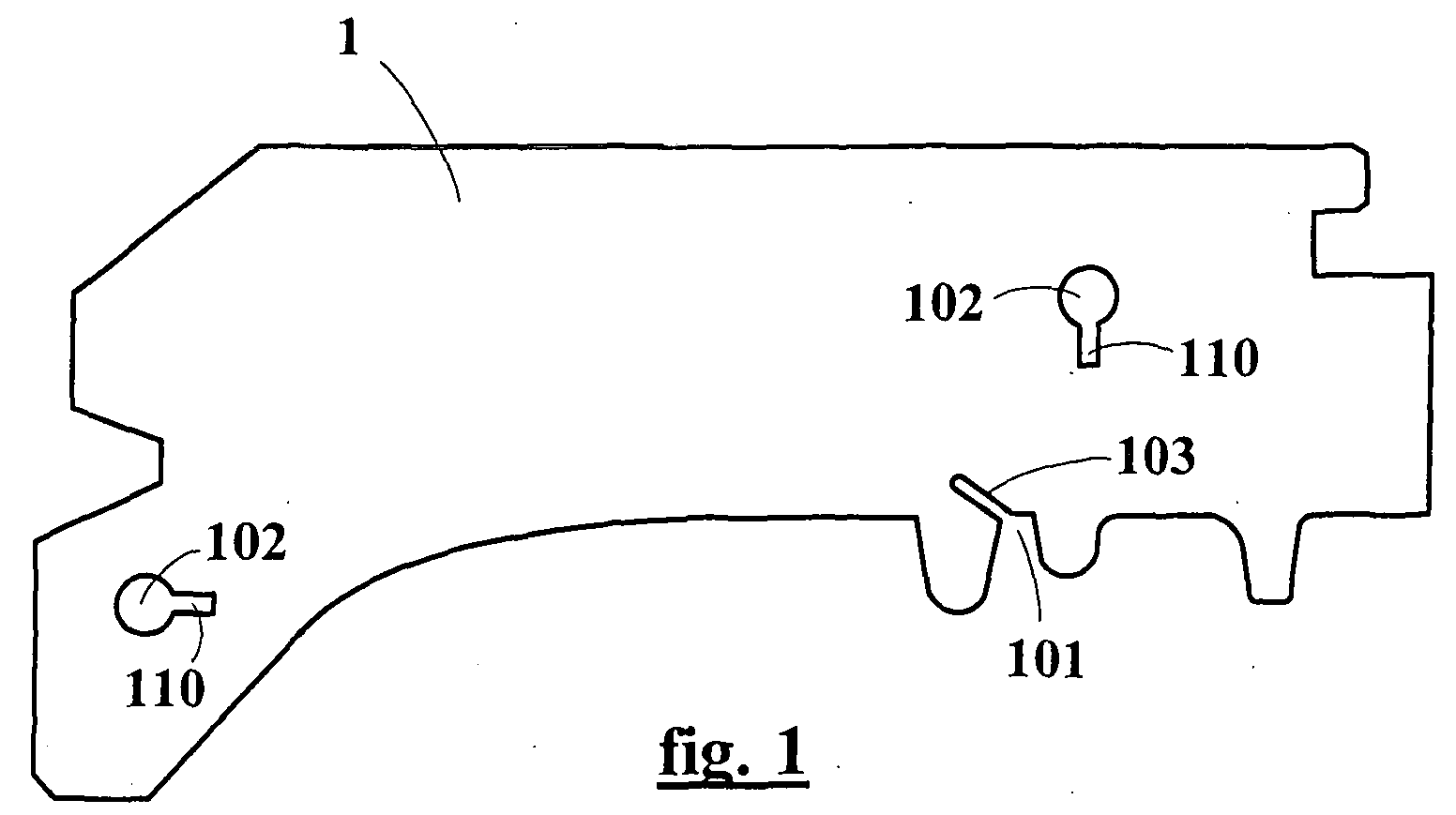
- Figure 1 shows such a sheet 1.
- a crown laminated can include a few thousand adjacent sheets.
- the thickness of the sheets corresponds to the resolution of the mold to define the sculpture.
- We for example uses steel sheets; they are advantageously cut all perpendicularly to their plan, according to a profile dictated by the patterns of sculpture that must be achieved. By cutting the sheets always perpendicularly, certain surfaces of the tread pattern will have the appearance of stair treads, which gives the tread of the molded tire a characteristic appearance of this technology.
- these sheets 1 may include partial cutouts (102, 103, 104, 105, 106, 107). These cuts are such that when the sheets are in place against the others, they create a venting channel connecting the interior of the mold (or all minus an area close to the molding surface) outside the mold. Cooperating several sheets to create a channel is advantageous because it is preferable that each sheet remains complete and monobloc. In addition, this cooperation brings other advantages. This allows, in distributing the cuts on several sheets, not to weaken a sheet excessively compared to other. This can also create channels or section channel portions important without being limited to the unit thickness of the sheets. This venting is different from that which can take place between the sheets according to the principles described in EP 569 909 and EP 860 260.
- the reference 103 corresponds to an example of cutting leading to the edge inside the sheet, that is to say at the molding surface of the mold.
- the through cutout 103 allows in the example of FIG. 1, to stop the stopping of a tread element 101 of the tire.
- Sheet neighbor shown in Figure 2 has a cutout 104 connecting the conduit created by the cutout opening 103 at the cutout 102.
- the connection cutouts 104 can take any shape suitable and compatible with their method of production. Cutouts 102 are similar on each sheet metal of a group considered.
- FIG. 4 represents another example of connection cutouts 106 and 107 suitable for allowing other configuration of venting networks according to the invention.
- this type of cutout 106 and 107 can also be used in the absence of through cutouts 103 on the adjacent sheets of the type of that of FIG. 1.
- the cutouts 106 or 107 have the function of improving the venting which takes place between the sheets.
- the venting between sheets is described in patent EP 569,909.
- This type of venting is improved according to the present invention in that the distance between the interior of the mold from the cutouts 106 or 107 is reduced by compared to that which separates the inner edge from the outer edge of the sheets.
- the cuts 106 and 107 extend substantially along the inner edge 10 at a distance "d" from the surface of molding, that is to say of the part of the nearest slice, d being preferably less than 10 mm.
- FIGS. 5A and 5B illustrate a preferred variant of the invention in which the elements of weak thickness 1 include deformations 108.
- These deformations 108 can simply be obtained by stamping in the case of sheets. These deformations constitute springs whose role is to separate the sheets when the mold opens, that is to say at each molding cycle. This has the effect to prevent certain parts of the mold from losing their venting potential over the molding because some sheets would remain joined when the mold was opened.
- these deformations 108 are distributed over all of the sheets constituting the circumference of the mold so that the spreading movement is substantially uniform along the circumference of the mold. In For this purpose, one can for example provide that one sheet out of two has this arrangement.
- the height of elastic deformations 108 is preferably between 0.01 and 0.1 mm.
- FIG. 6 shows a meridian section of a mold according to the invention.
- the crown is divided in two parts (G and D), and comprises, transversely, two separate and adjacent sheets (1G and 1D) each belonging to one of the parties.
- the sheets or molding elements are generally designated by the reference 1.
- the reference 1G is used.
- the reference 1D is used.
- This mold is formed by a large number of sheets 1 as described above and by shells 111G and 111D molding the sidewalls of the tire.
- the sheets are supported on the shells and are guided by a belt 112 and conical frets 113G and 113D. a unitary sheet molding the entire width of the strip bearing can also replace the two sheets 1G and 1D.
- the functioning of these different types of mold is described in patent EP 0 569 909.
- FIGS 7 to 12 illustrate a preferred embodiment characterized by the grouping of the sheets in subassemblies.
- the cutouts described above are not shown.
- Each of these subsets (or only a limited number of them) contains one or more sheets such as set out above, that is to say comprising partial venting cutouts.
- FIG. 7 represents this principle of the invention according to which the thin elements 1 of the laminated crowns are grouped in one-piece sub-assemblies constituting sectors 11.
- the crown is divided into two parts (G and D), and that the crown has, transversely, two separate (1G and 1D) and adjacent sheets each belonging to one of the parts.
- the sheets or molding elements are generally designated by the reference 1.
- At least the end on the molding part side that is to say on the edge side 10 of the sheets 1, has a progressively decreasing thickness as it moves radially towards the axis of the mold.
- Each of the sheets thus forms a slight wedge, the angle of which corresponds substantially to the value obtained by dividing 360 ° by the number of sheets on one revolution in the peripheral molding ring.
- the sheets can naturally be arranged in a fan when they are brought together and present between they play a substantially constant game.
- patent applications EP 0 916 419 and EP 0 916 421 see patent applications EP 0 916 419 and EP 0 916 421.
- the sheets 1 are grouped by sectors 11, as is sees very well in particular in Figures 7, 9 and 10.
- the sheets 1 of a sector 11 are taken in pincers by a fixing device comprising two protruding heads, such as a bolt 2 (whose head forms a first head 21) and a nut 22 (forming the second head).
- the head 21 of each bolt 2 and nut 22 press on the free flank 15 of each of the sheets la at the edge of each sector 11.
- the fixing devices (bolt 2 and nut 22 assemblies) are arranged alternately with a sector to the other (see Figures 7 and 10), each sector having recesses 12 for accommodating the head fixing devices for adjacent sectors.
- the recesses 12 are obtained by creating holes in a sufficient number of sheets when cutting said sheets. This brings the sectors in contact (see Figure 9) to form the continuous crown ensuring the molding of the strip of rolling.
- the fixing means are arranged in the common cutouts 102 (see FIGS. 1 to 5).
- the presence of a wing 110 (see FIGS. 1 to SA) on the profile of the common cutouts 102 ensures that the circulation of venting gases is not limited by the means of fixing of sheet metal bundles.
- the recesses 12 can be connected to the cutouts 102 in order to allow the circulation of venting gases from one block to another despite the shift in means of fixing and therefore the fact that the cutouts 102 are not opposite one sub-assembly to another. This connection can be established by an additional cutout (not shown) connecting at least one recess 12 and a cutout 102 of at least one of the sheets concerned by said recesses 12.
- the number of elements per sector is typically between 10 and 1000.
- the number of elements is identical for all sectors, or different from one sector to another.
- Different means can be used to handle the groups of assembled and maintained sheets into sectors. This involves organizing the movements of sectors necessary to open and close the mold. We can for example fix the sheets belonging to a sector on a box, each box can be moved during opening and closing movements of the mold.
- each sector 11 is mounted on a housing 4 forming a one-piece support, can be a standard piece common to a large number of different sculptures. Naturally, this is only an example of realization. Even if a case 4 is of course generally adapted to the dimension of a tire, since it is not in itself molding, it can be used for several different treads and is therefore not specific to a single tire. To achieve this fixing, the sheets are cut so as to obtain grooves 14 which are engaged on a protuberance 41 arranged on one side on the housing 4, the sector being immobilized by a flange 40, also in engagement in another groove 14 of each sheet and screwed onto the housing 4. Thus, the sheets 1 belonging to a sector 11 are fixed on a case 4, each case 4 can then be moved during movements opening and closing the mold. The number of sheets can be identical for all sectors, or well the sectors can collect a different number of sheets.
- Each of the housings comprises, in addition to the protuberance 41, a lateral edge 46, a back 43, and a central edge 48 intended to come into contact with the corresponding central edge 48 of the housing adjacent to the other part.
- a lug 49a on each of the housings 4 of part D engaged in a cutout 49b made on each of the housings 4 of part G, in order to position with great precision the boxes 4 and therefore the sheets 1 at the same height radially during the entire phase of closing the mold, especially during the final closing phase.
- each of the housings 4 is mounted on a ramp 3 by means of a slide (not shown), in order to allow a relative movement symbolized by an arrow drawn on the back of the case.
- each of the parts G and D of the mold comprises a plate 5 on which is mounted a ramp 3.
- the ramp 3 has a frustoconical bearing 30 of angle ⁇ , radially inside, in contact with said boxes 4. This ramp makes it possible to control the movement of boxes 4 to bring them into their closed position, as shown in Figure 8, or to bring them into their position opening (not shown in FIG. 8, but corresponding for the groups of sheets in FIG. 10), as known per se for sector molds in two axial parts.
- the sheets 1 are mounted on the housing being all arranged according to the same angle to the radial direction.
- the sheets are arranged in a meridian manner.
- the sheets are arranged so that include a radius, and their virtual extension includes the geometric axis of the mold. This is not in no way limitative and we can admit that the sheets are somewhat inclined.
- the invention is not limited to the category of mold comprising two parts (L and R) axially, but may equally find interest in applying to another category of molds, axially in a single part.
- the elements used are 1L sheets whose width corresponds substantially to the width of the tread. Each sector is mounted on a 4L case also forming a monobloc support, which can also be a standard part common to a large number of different sculptures, of suitable width. 1L sheets are fixed with grooves 14L engaged on 41L protrusions arranged on one side on the 4L case and on the other on a 40L flange which is screwed onto the 4L case.
- the invention makes it possible to manufacture molds having a high venting potential in a manner which blends well with computer-aided design and production techniques, with a delay of very short realization.
- the molds thus produced are very robust; they get along very well with a large number of opening and closing cycles, in particular because the venting takes place in part at least through the venting channels (in addition to the venting that takes place between the molding elements).
- the molds according to the invention make it possible to produce tires of better quality while limiting the maintenance required to maintain the potential for venting. In addition they allow to mold tires with more discreet vent marks.
- the molding nipples created by the through cutouts 103 are not necessarily perpendicular to the molding surface as is generally the case for conventional molds (not laminated), the vents result from holes passing through the molding elements.
- teats we also use the term "beard”
- An orientation of these teats at an angle less than 60 ° for example of the order of 45 ° relative to the surface of the strip of rolling represents an advantageous compromise between the criteria of aspect and that of the constraints of release.
Landscapes
- Engineering & Computer Science (AREA)
- Mechanical Engineering (AREA)
- Moulds For Moulding Plastics Or The Like (AREA)
- Heating, Cooling, Or Curing Plastics Or The Like In General (AREA)
Abstract
Description
Claims (13)
- Moule pour bande de roulement de pneumatique, comportant une couronne périphérique feuilletée pour le moulage de l'extérieur de la bande de roulement, ladite couronne périphérique feuilletée comprenant un empilage dans la direction circonférentielle d'une pluralité d'éléments moulants (1) de faible épaisseur, lesdits éléments étant orientés sensiblement radialement, le moulage de ladite bande de roulement étant effectué par la tranche (10) radialement intérieure desdits éléments, ladite tranche ayant le profil voulu pour mouler une sculpture sur la bande de roulement, caractérisé en ce que plusieurs éléments moulants adjacents comporte des découpes partielles (102, 104, 105, 106, 107) qui coopèrent entre elles pour former au moins un canal d'éventation.
- Moule selon la revendication 1 dont l'ensemble des élément moulants (1) comportent des découpes (102) en regard les unes par rapport aux autres de sorte qu'elles créent un conduit sensiblement circonférentiel connectant entre elles des découpes de liaison (104) et au moins une découpe d'extraction (105).
- Moule selon l'une des revendications précédentes dans lequel des éléments moulants (1) comportent des découpes débouchantes (103) reliant ledit canal d'éventation au volume intérieur du moule.
- Moule selon l'une des revendications 1 ou 2 dans lequel les découpes partielles (106, 107) s'étendent sensiblement le long de la tranche intérieure (10) à une distance "d" de la partie la plus proche de la tranche, d étant inférieure à 10 mm.
- Moule selon l'une des revendications précédentes dans lequel des éléments moulants (1) comportent des déformations (108) aptes à assurer une fonction de ressort tendant à écarter les éléments les uns des autres lorsque le moule est ouvert.
- Moule selon l'une des revendications précédentes dans lequel la couronne est divisée en secteurs (11) et dans lequel, pour chaque secteur, les éléments appartenant à un secteur sont solidarisés entre eux pour former un bloc unitaire, chaque secteur pouvant être déplacé lors des mouvements d'ouverture et de fermeture du moule.
- Moule selon la revendication 6, dans lequel les éléments appartenant à un secteur sont fixés sur un boítier (4), chaque boítier pouvant être déplacé lors des mouvements d'ouverture et de fermeture du moule.
- Moule selon l'une des revendications 6 ou 7, dans lequel la couronne est divisée en deux parties (G, D), en ce que la couronne comporte, transversalement, deux éléments (1G, 1D) distincts et adjacents appartenant chacun à l'une des parties.
- Moule selon l'une des revendications 6 à 8, caractérisé en ce que chaque élément a une épaisseur comprise entre 0,1 mm et 5 mm, et en ce que l'extrémité côté tranche (10) de moulage desdits éléments présente une épaisseur progressivement décroissante en se déplaçant radialement vers l'axe du moule.
- Moule selon l'une des revendications 6 à 9, dans lequel les éléments d'un secteur sont pris en tenaille par un dispositif de fixation comportant deux têtes faisant protubérance et appuyant chacune sur le flanc libre de chacun des éléments au bord du secteur, les dispositifs de fixation étant disposés en alternance d'un secteur à l'autre, chaque secteur comportant des évidements (12) permettant de loger la tête des dispositifs de fixation des secteurs adjacents lorsque les secteurs sont en contact pour former ladite couronne de moulage de la bande de roulement.
- Moule selon l'une des revendications 6 à 10, comportant un nombre pair de secteurs.
- Procédé de fabrication d'un pneu, caractérisé en ce que l'on utilise un moule selon l'une des revendications 1 à 11, dans lequel l'éventation du moule se fait au moins en partie par ledit au moins un canal d'éventation.
- Pneumatique obtenu par le procédé de la revendication 12, comportant des tétines de moulage orientées selon un angle inférieur à 60° par rapport à la surface de la bande de roulement.
Applications Claiming Priority (2)
| Application Number | Priority Date | Filing Date | Title |
|---|---|---|---|
| FR0205397A FR2839003A1 (fr) | 2002-04-29 | 2002-04-29 | Moule pour pneus |
| FR0205397 | 2002-04-29 |
Publications (3)
| Publication Number | Publication Date |
|---|---|
| EP1361042A2 true EP1361042A2 (fr) | 2003-11-12 |
| EP1361042A3 EP1361042A3 (fr) | 2004-12-22 |
| EP1361042B1 EP1361042B1 (fr) | 2006-10-04 |
Family
ID=28800043
Family Applications (1)
| Application Number | Title | Priority Date | Filing Date |
|---|---|---|---|
| EP03008212A Expired - Lifetime EP1361042B1 (fr) | 2002-04-29 | 2003-04-09 | Moule pour pneus et procédé de moulage de pneus utilisant ce moule. |
Country Status (8)
| Country | Link |
|---|---|
| US (1) | US7118702B2 (fr) |
| EP (1) | EP1361042B1 (fr) |
| JP (1) | JP4374212B2 (fr) |
| CN (1) | CN100354097C (fr) |
| AT (1) | ATE341442T1 (fr) |
| BR (1) | BR0301265A (fr) |
| DE (1) | DE60308745T2 (fr) |
| FR (1) | FR2839003A1 (fr) |
Cited By (8)
| Publication number | Priority date | Publication date | Assignee | Title |
|---|---|---|---|---|
| WO2004076149A1 (fr) * | 2003-02-26 | 2004-09-10 | Continental Aktiengesellschaft | Moule de vulcanisation pour pneus de vehicule |
| EP1527865A4 (fr) * | 2002-07-01 | 2009-01-21 | Bridgestone Corp | Procede de fabrication d'un moule stratifie et moule stratifie |
| EP2669078A1 (fr) * | 2012-05-29 | 2013-12-04 | Sumitomo Rubber Industries, Ltd. | Moule de vulcanisation de pneu et procédé de fabrication d'un pneu |
| WO2019211709A1 (fr) | 2018-04-30 | 2019-11-07 | Compagnie Générale Des Établissements Michelin | Element moulant avec fente d'evacuation d'air convergente |
| WO2019211711A1 (fr) | 2018-04-30 | 2019-11-07 | Compagnie Générale Des Établissements Michelin | Element moulant avec fente d'evacuation de l'air et secteur de micro-moulage |
| WO2019211710A1 (fr) | 2018-04-30 | 2019-11-07 | Compagnie Générale Des Établissements Michelin | Element moulant avec fente d'evacuation d'air divergente |
| WO2020021368A1 (fr) | 2018-07-21 | 2020-01-30 | Compagnie Générale Des Établissements Michelin | Procede de realisation d'un element moulant comprenant un moyen d'eventation |
| WO2020021369A1 (fr) | 2018-07-21 | 2020-01-30 | Compagnie Générale Des Établissements Michelin | Procédé de réalisation d'un élément moulant avec fente d'évacuation d'air |
Families Citing this family (10)
| Publication number | Priority date | Publication date | Assignee | Title |
|---|---|---|---|---|
| FR2832091A1 (fr) * | 2001-11-13 | 2003-05-16 | Michelin Soc Tech | Moule pour pneus |
| KR100593436B1 (ko) * | 2004-09-10 | 2006-06-28 | 한국생산기술연구원 | 중공형 타이어 가류몰드 |
| JP5210548B2 (ja) * | 2007-05-29 | 2013-06-12 | 東洋ゴム工業株式会社 | タイヤトレッド加硫金型 |
| WO2010019134A1 (fr) * | 2008-08-12 | 2010-02-18 | Societe De Technologie Michelin | Moule présentant un outillage de moule |
| JP5265504B2 (ja) * | 2009-12-03 | 2013-08-14 | 住友ゴム工業株式会社 | タイヤ用モールド |
| JP5066220B2 (ja) * | 2010-05-17 | 2012-11-07 | 住友ゴム工業株式会社 | 空気入りタイヤ及びその製造方法 |
| JP5117541B2 (ja) * | 2010-06-23 | 2013-01-16 | 住友ゴム工業株式会社 | タイヤ用モールド |
| JP5658094B2 (ja) * | 2011-06-02 | 2015-01-21 | 住友ゴム工業株式会社 | タイヤ用モールド |
| CN102950249A (zh) * | 2011-08-25 | 2013-03-06 | 无锡蕾菲赛尔机械科技有限公司 | 一种铝合金轮胎模具的铸造装置 |
| JP5417493B2 (ja) * | 2012-07-09 | 2014-02-12 | 住友ゴム工業株式会社 | タイヤ用モールド |
Family Cites Families (17)
| Publication number | Priority date | Publication date | Assignee | Title |
|---|---|---|---|---|
| JPS61108512A (ja) * | 1984-10-31 | 1986-05-27 | Sumitomo Rubber Ind Ltd | タイヤ加硫用金型 |
| IT1189674B (it) * | 1986-05-20 | 1988-02-04 | Firestone Int Dev Spa | Unita mobile di vulcanizzazione per pneumatici |
| US4881881A (en) * | 1988-02-08 | 1989-11-21 | The Uniroyal Goodrich Tire Company | Plug-resistant arch-vents for a tire mold |
| JPH02295706A (ja) * | 1989-05-10 | 1990-12-06 | Yokohama Rubber Co Ltd:The | セクショナル型タイヤ成形金型及びその製作方法 |
| IT1240295B (it) * | 1990-04-13 | 1993-12-07 | Pirelli | Stampo e metodo per la vulcanizzazione di pneumatici e metodo per fabbricare stampi |
| ATE191675T1 (de) | 1992-05-13 | 2000-04-15 | Sedepro | Luftreifen |
| JP2796215B2 (ja) | 1992-05-21 | 1998-09-10 | 日清食品株式会社 | 麺線の型詰方法 |
| TW228512B (fr) | 1992-08-10 | 1994-08-21 | Showa Denko Kk | |
| FR2708516A1 (fr) * | 1993-08-06 | 1995-02-10 | Sedepro | Moule pour pneumatique et procédé de moulage de pneumatique. |
| FR2712229A1 (fr) * | 1993-11-12 | 1995-05-19 | Sedepro | Moule pour pneumatique, et procédé de moulage du pneumatique. |
| FR2759626A1 (fr) * | 1997-02-19 | 1998-08-21 | Sedepro | Moule pour pneus |
| FR2770792A1 (fr) | 1997-11-13 | 1999-05-14 | Conception & Dev Michelin Sa | Usinage d'une tole sans enlevement de matiere par ecrasement |
| FR2770793A1 (fr) | 1997-11-13 | 1999-05-14 | Conception & Dev Michelin Sa | Usinage de tole sans elevement de matiere, par etirage |
| JPH11300746A (ja) * | 1998-04-24 | 1999-11-02 | Yokohama Rubber Co Ltd:The | タイヤ成形用金型及びその製造方法 |
| DE19914215A1 (de) * | 1999-03-29 | 2000-10-05 | Dunlop Gmbh | Vulkanisationsform mit Entlüftungsöffnungen zur Herstellung technischer Gummiprodukte |
| JP2002002224A (ja) * | 2000-06-19 | 2002-01-08 | Bridgestone Corp | 空気入りタイヤ及び空気入りタイヤ用の加硫金型 |
| AU2003302931A1 (en) * | 2002-12-07 | 2004-06-30 | Cooper Technology Services, Llc | Annular venting of tire tread molds |
-
2002
- 2002-04-29 FR FR0205397A patent/FR2839003A1/fr active Pending
-
2003
- 2003-04-09 EP EP03008212A patent/EP1361042B1/fr not_active Expired - Lifetime
- 2003-04-09 AT AT03008212T patent/ATE341442T1/de not_active IP Right Cessation
- 2003-04-09 DE DE60308745T patent/DE60308745T2/de not_active Expired - Lifetime
- 2003-04-28 BR BR0301265-4A patent/BR0301265A/pt not_active Application Discontinuation
- 2003-04-28 JP JP2003158680A patent/JP4374212B2/ja not_active Expired - Fee Related
- 2003-04-28 CN CNB031224660A patent/CN100354097C/zh not_active Expired - Fee Related
- 2003-04-29 US US10/425,526 patent/US7118702B2/en not_active Expired - Fee Related
Cited By (10)
| Publication number | Priority date | Publication date | Assignee | Title |
|---|---|---|---|---|
| EP1527865A4 (fr) * | 2002-07-01 | 2009-01-21 | Bridgestone Corp | Procede de fabrication d'un moule stratifie et moule stratifie |
| WO2004076149A1 (fr) * | 2003-02-26 | 2004-09-10 | Continental Aktiengesellschaft | Moule de vulcanisation pour pneus de vehicule |
| EP2669078A1 (fr) * | 2012-05-29 | 2013-12-04 | Sumitomo Rubber Industries, Ltd. | Moule de vulcanisation de pneu et procédé de fabrication d'un pneu |
| US8757995B2 (en) | 2012-05-29 | 2014-06-24 | Sumitomo Rubber Industries, Ltd. | Tire vulcanization mold |
| WO2019211709A1 (fr) | 2018-04-30 | 2019-11-07 | Compagnie Générale Des Établissements Michelin | Element moulant avec fente d'evacuation d'air convergente |
| WO2019211711A1 (fr) | 2018-04-30 | 2019-11-07 | Compagnie Générale Des Établissements Michelin | Element moulant avec fente d'evacuation de l'air et secteur de micro-moulage |
| WO2019211710A1 (fr) | 2018-04-30 | 2019-11-07 | Compagnie Générale Des Établissements Michelin | Element moulant avec fente d'evacuation d'air divergente |
| WO2020021368A1 (fr) | 2018-07-21 | 2020-01-30 | Compagnie Générale Des Établissements Michelin | Procede de realisation d'un element moulant comprenant un moyen d'eventation |
| WO2020021369A1 (fr) | 2018-07-21 | 2020-01-30 | Compagnie Générale Des Établissements Michelin | Procédé de réalisation d'un élément moulant avec fente d'évacuation d'air |
| US12122070B2 (en) | 2018-07-21 | 2024-10-22 | Compagnie Generale Des Etablissements Michelin | Method for producing a molding element having an air discharge slot |
Also Published As
| Publication number | Publication date |
|---|---|
| DE60308745D1 (de) | 2006-11-16 |
| FR2839003A1 (fr) | 2003-10-31 |
| JP4374212B2 (ja) | 2009-12-02 |
| US20030218276A1 (en) | 2003-11-27 |
| JP2003320535A (ja) | 2003-11-11 |
| ATE341442T1 (de) | 2006-10-15 |
| CN100354097C (zh) | 2007-12-12 |
| DE60308745T2 (de) | 2007-02-01 |
| EP1361042B1 (fr) | 2006-10-04 |
| BR0301265A (pt) | 2004-08-17 |
| EP1361042A3 (fr) | 2004-12-22 |
| US7118702B2 (en) | 2006-10-10 |
| CN1454767A (zh) | 2003-11-12 |
Similar Documents
| Publication | Publication Date | Title |
|---|---|---|
| EP1361042B1 (fr) | Moule pour pneus et procédé de moulage de pneus utilisant ce moule. | |
| CA2135577C (fr) | Moule pour pneumatique, et procede de moulage du pneumatique | |
| CA2096205C (fr) | Moule pour pneumatique, et procede de moulage du pneumatique | |
| EP3137289B1 (fr) | Element de moule pour moule de pneumatique comportant un marquage | |
| EP0860260B1 (fr) | Moule pour pneus | |
| EP1109946B1 (fr) | Support pour lentille optique, et son procede de mise en oeuvre | |
| EP3030410B1 (fr) | Moule pour pneumatique comportant une coquille avec parties amovibles | |
| EP2914400B1 (fr) | Procédé de fabrication par usinage de lentilles ophtalmiques | |
| FR2907699A1 (fr) | Patin de polissage ayant des rainures espacees de maniere irreguliere | |
| WO2010076521A1 (fr) | Moule pour la vulcanisation d'un pneumatique comprenant un reseau de canaux et d'entailles | |
| EP2382065A2 (fr) | Procede de fabrication d'un element de garniture et d'un element de soutien destines a un moule de pneumatique | |
| WO2012035477A1 (fr) | Procédé de fabrication d'une structure optique segmentée | |
| EP1446275B1 (fr) | Moule pour pneus | |
| EP2578376A1 (fr) | Pièce optique comprenant une ame et une pluralité de couches | |
| FR2563772A1 (fr) | Dispositif pour mouler par injection des disques support d'enregistrement | |
| FR3045436A1 (fr) | Moule autobloquant pour le moulage et la vulcanisation des pneumatiques comprenant une rondelle epaule | |
| FR2699853A1 (fr) | Moule pour pneumatique, et procédé de moulage du pneumatique. | |
| EP3490787B1 (fr) | Moule de vulcanisation pour pneumatique et procédé d'assemblage des garnitures du moule. | |
| FR3071031B1 (fr) | Procede de realisation d'un ecran de couleurs pour un dispositif d'eclairage et/ou de signalisation pour vehicule automobile | |
| FR3113472A1 (fr) | Moule de cuisson pour pneumatique comportant des moyens de découpage d’une bavure de gomme | |
| FR2691095A1 (fr) | Moule pour pneumatique, et procédé de moulage du pneumatique. | |
| FR3055245A1 (fr) | Element modulaire sous forme de plaque pour la decoration d'une surface, et procede de realisation d'un decor au moyen d'un tel element | |
| FR3006396A1 (fr) | Realisation d'excroissances de retenue des corps roulants d'une cage de roulement. | |
| BE648698A (fr) |
Legal Events
| Date | Code | Title | Description |
|---|---|---|---|
| PUAI | Public reference made under article 153(3) epc to a published international application that has entered the european phase |
Free format text: ORIGINAL CODE: 0009012 |
|
| AK | Designated contracting states |
Kind code of ref document: A2 Designated state(s): AT BE BG CH CY CZ DE DK EE ES FI FR GB GR HU IE IT LI LU MC NL PT RO SE SI SK TR |
|
| AX | Request for extension of the european patent |
Extension state: AL LT LV MK |
|
| PUAL | Search report despatched |
Free format text: ORIGINAL CODE: 0009013 |
|
| AK | Designated contracting states |
Kind code of ref document: A3 Designated state(s): AT BE BG CH CY CZ DE DK EE ES FI FR GB GR HU IE IT LI LU MC NL PT RO SE SI SK TR |
|
| AX | Request for extension of the european patent |
Extension state: AL LT LV MK |
|
| 17P | Request for examination filed |
Effective date: 20050622 |
|
| AKX | Designation fees paid |
Designated state(s): AT BE BG CH CY CZ DE DK EE ES FI FR GB GR HU IE IT LI LU MC NL PT RO SE SI SK TR |
|
| GRAP | Despatch of communication of intention to grant a patent |
Free format text: ORIGINAL CODE: EPIDOSNIGR1 |
|
| RTI1 | Title (correction) |
Free format text: TYRE MOULD AND TYRE MOULDING PROCESS USING SUCH A MOULD. |
|
| GRAS | Grant fee paid |
Free format text: ORIGINAL CODE: EPIDOSNIGR3 |
|
| RAP1 | Party data changed (applicant data changed or rights of an application transferred) |
Owner name: MICHELIN RECHERCHE ET TECHNIQUE S.A. Owner name: SOCIETE DE TECHNOLOGIE MICHELIN |
|
| GRAA | (expected) grant |
Free format text: ORIGINAL CODE: 0009210 |
|
| AK | Designated contracting states |
Kind code of ref document: B1 Designated state(s): AT BE BG CH CY CZ DE DK EE ES FI FR GB GR HU IE IT LI LU MC NL PT RO SE SI SK TR |
|
| PG25 | Lapsed in a contracting state [announced via postgrant information from national office to epo] |
Ref country code: AT Free format text: LAPSE BECAUSE OF FAILURE TO SUBMIT A TRANSLATION OF THE DESCRIPTION OR TO PAY THE FEE WITHIN THE PRESCRIBED TIME-LIMIT Effective date: 20061004 Ref country code: SK Free format text: LAPSE BECAUSE OF FAILURE TO SUBMIT A TRANSLATION OF THE DESCRIPTION OR TO PAY THE FEE WITHIN THE PRESCRIBED TIME-LIMIT Effective date: 20061004 Ref country code: CZ Free format text: LAPSE BECAUSE OF FAILURE TO SUBMIT A TRANSLATION OF THE DESCRIPTION OR TO PAY THE FEE WITHIN THE PRESCRIBED TIME-LIMIT Effective date: 20061004 Ref country code: IE Free format text: LAPSE BECAUSE OF FAILURE TO SUBMIT A TRANSLATION OF THE DESCRIPTION OR TO PAY THE FEE WITHIN THE PRESCRIBED TIME-LIMIT Effective date: 20061004 Ref country code: NL Free format text: LAPSE BECAUSE OF FAILURE TO SUBMIT A TRANSLATION OF THE DESCRIPTION OR TO PAY THE FEE WITHIN THE PRESCRIBED TIME-LIMIT Effective date: 20061004 Ref country code: FI Free format text: LAPSE BECAUSE OF FAILURE TO SUBMIT A TRANSLATION OF THE DESCRIPTION OR TO PAY THE FEE WITHIN THE PRESCRIBED TIME-LIMIT Effective date: 20061004 Ref country code: SI Free format text: LAPSE BECAUSE OF FAILURE TO SUBMIT A TRANSLATION OF THE DESCRIPTION OR TO PAY THE FEE WITHIN THE PRESCRIBED TIME-LIMIT Effective date: 20061004 Ref country code: IT Free format text: LAPSE BECAUSE OF FAILURE TO SUBMIT A TRANSLATION OF THE DESCRIPTION OR TO PAY THE FEE WITHIN THE PRESCRIBED TIME-LIMIT;WARNING: LAPSES OF ITALIAN PATENTS WITH EFFECTIVE DATE BEFORE 2007 MAY HAVE OCCURRED AT ANY TIME BEFORE 2007. THE CORRECT EFFECTIVE DATE MAY BE DIFFERENT FROM THE ONE RECORDED. Effective date: 20061004 |
|
| REG | Reference to a national code |
Ref country code: GB Ref legal event code: FG4D Free format text: NOT ENGLISH |
|
| REG | Reference to a national code |
Ref country code: CH Ref legal event code: EP |
|
| REG | Reference to a national code |
Ref country code: IE Ref legal event code: FG4D Free format text: LANGUAGE OF EP DOCUMENT: FRENCH |
|
| REF | Corresponds to: |
Ref document number: 60308745 Country of ref document: DE Date of ref document: 20061116 Kind code of ref document: P |
|
| GBT | Gb: translation of ep patent filed (gb section 77(6)(a)/1977) |
Effective date: 20061108 |
|
| PG25 | Lapsed in a contracting state [announced via postgrant information from national office to epo] |
Ref country code: SE Free format text: LAPSE BECAUSE OF FAILURE TO SUBMIT A TRANSLATION OF THE DESCRIPTION OR TO PAY THE FEE WITHIN THE PRESCRIBED TIME-LIMIT Effective date: 20070104 Ref country code: DK Free format text: LAPSE BECAUSE OF FAILURE TO SUBMIT A TRANSLATION OF THE DESCRIPTION OR TO PAY THE FEE WITHIN THE PRESCRIBED TIME-LIMIT Effective date: 20070104 Ref country code: BG Free format text: LAPSE BECAUSE OF FAILURE TO SUBMIT A TRANSLATION OF THE DESCRIPTION OR TO PAY THE FEE WITHIN THE PRESCRIBED TIME-LIMIT Effective date: 20070104 |
|
| PG25 | Lapsed in a contracting state [announced via postgrant information from national office to epo] |
Ref country code: ES Free format text: LAPSE BECAUSE OF FAILURE TO SUBMIT A TRANSLATION OF THE DESCRIPTION OR TO PAY THE FEE WITHIN THE PRESCRIBED TIME-LIMIT Effective date: 20070115 |
|
| PG25 | Lapsed in a contracting state [announced via postgrant information from national office to epo] |
Ref country code: PT Free format text: LAPSE BECAUSE OF FAILURE TO SUBMIT A TRANSLATION OF THE DESCRIPTION OR TO PAY THE FEE WITHIN THE PRESCRIBED TIME-LIMIT Effective date: 20070316 |
|
| NLV1 | Nl: lapsed or annulled due to failure to fulfill the requirements of art. 29p and 29m of the patents act | ||
| REG | Reference to a national code |
Ref country code: IE Ref legal event code: FD4D |
|
| PLBE | No opposition filed within time limit |
Free format text: ORIGINAL CODE: 0009261 |
|
| STAA | Information on the status of an ep patent application or granted ep patent |
Free format text: STATUS: NO OPPOSITION FILED WITHIN TIME LIMIT |
|
| 26N | No opposition filed |
Effective date: 20070705 |
|
| REG | Reference to a national code |
Ref country code: CH Ref legal event code: PL |
|
| BERE | Be: lapsed |
Owner name: SOC. DE TECHNOLOGIE MICHELIN Effective date: 20070430 Owner name: MICHELIN RECHERCHE ET TECHNIQUE S.A. Effective date: 20070430 |
|
| PG25 | Lapsed in a contracting state [announced via postgrant information from national office to epo] |
Ref country code: RO Free format text: LAPSE BECAUSE OF FAILURE TO SUBMIT A TRANSLATION OF THE DESCRIPTION OR TO PAY THE FEE WITHIN THE PRESCRIBED TIME-LIMIT Effective date: 20061004 |
|
| PG25 | Lapsed in a contracting state [announced via postgrant information from national office to epo] |
Ref country code: CH Free format text: LAPSE BECAUSE OF NON-PAYMENT OF DUE FEES Effective date: 20070430 Ref country code: LI Free format text: LAPSE BECAUSE OF NON-PAYMENT OF DUE FEES Effective date: 20070430 |
|
| PG25 | Lapsed in a contracting state [announced via postgrant information from national office to epo] |
Ref country code: BE Free format text: LAPSE BECAUSE OF NON-PAYMENT OF DUE FEES Effective date: 20070430 |
|
| PG25 | Lapsed in a contracting state [announced via postgrant information from national office to epo] |
Ref country code: GR Free format text: LAPSE BECAUSE OF FAILURE TO SUBMIT A TRANSLATION OF THE DESCRIPTION OR TO PAY THE FEE WITHIN THE PRESCRIBED TIME-LIMIT Effective date: 20070105 |
|
| PG25 | Lapsed in a contracting state [announced via postgrant information from national office to epo] |
Ref country code: EE Free format text: LAPSE BECAUSE OF FAILURE TO SUBMIT A TRANSLATION OF THE DESCRIPTION OR TO PAY THE FEE WITHIN THE PRESCRIBED TIME-LIMIT Effective date: 20061004 |
|
| PG25 | Lapsed in a contracting state [announced via postgrant information from national office to epo] |
Ref country code: MC Free format text: LAPSE BECAUSE OF NON-PAYMENT OF DUE FEES Effective date: 20070430 |
|
| PG25 | Lapsed in a contracting state [announced via postgrant information from national office to epo] |
Ref country code: LU Free format text: LAPSE BECAUSE OF NON-PAYMENT OF DUE FEES Effective date: 20070409 Ref country code: CY Free format text: LAPSE BECAUSE OF FAILURE TO SUBMIT A TRANSLATION OF THE DESCRIPTION OR TO PAY THE FEE WITHIN THE PRESCRIBED TIME-LIMIT Effective date: 20061004 |
|
| PG25 | Lapsed in a contracting state [announced via postgrant information from national office to epo] |
Ref country code: HU Free format text: LAPSE BECAUSE OF FAILURE TO SUBMIT A TRANSLATION OF THE DESCRIPTION OR TO PAY THE FEE WITHIN THE PRESCRIBED TIME-LIMIT Effective date: 20070405 Ref country code: TR Free format text: LAPSE BECAUSE OF FAILURE TO SUBMIT A TRANSLATION OF THE DESCRIPTION OR TO PAY THE FEE WITHIN THE PRESCRIBED TIME-LIMIT Effective date: 20061004 |
|
| PGFP | Annual fee paid to national office [announced via postgrant information from national office to epo] |
Ref country code: GB Payment date: 20090421 Year of fee payment: 7 |
|
| GBPC | Gb: european patent ceased through non-payment of renewal fee |
Effective date: 20100409 |
|
| PG25 | Lapsed in a contracting state [announced via postgrant information from national office to epo] |
Ref country code: GB Free format text: LAPSE BECAUSE OF NON-PAYMENT OF DUE FEES Effective date: 20100409 |
|
| PGFP | Annual fee paid to national office [announced via postgrant information from national office to epo] |
Ref country code: FR Payment date: 20110510 Year of fee payment: 9 Ref country code: DE Payment date: 20110421 Year of fee payment: 9 |
|
| REG | Reference to a national code |
Ref country code: FR Ref legal event code: ST Effective date: 20121228 |
|
| REG | Reference to a national code |
Ref country code: DE Ref legal event code: R119 Ref document number: 60308745 Country of ref document: DE Effective date: 20121101 |
|
| PG25 | Lapsed in a contracting state [announced via postgrant information from national office to epo] |
Ref country code: FR Free format text: LAPSE BECAUSE OF NON-PAYMENT OF DUE FEES Effective date: 20120430 |
|
| PG25 | Lapsed in a contracting state [announced via postgrant information from national office to epo] |
Ref country code: DE Free format text: LAPSE BECAUSE OF NON-PAYMENT OF DUE FEES Effective date: 20121101 |