EP1360934B2 - Vorrichtung und Verfahren zur Zufuhr und Analyse von einer physiologischen Flüssigkeit - Google Patents
Vorrichtung und Verfahren zur Zufuhr und Analyse von einer physiologischen Flüssigkeit Download PDFInfo
- Publication number
- EP1360934B2 EP1360934B2 EP03252883.8A EP03252883A EP1360934B2 EP 1360934 B2 EP1360934 B2 EP 1360934B2 EP 03252883 A EP03252883 A EP 03252883A EP 1360934 B2 EP1360934 B2 EP 1360934B2
- Authority
- EP
- European Patent Office
- Prior art keywords
- skin
- biosensor
- cartridge
- devices
- piercing
- Prior art date
- Legal status (The legal status is an assumption and is not a legal conclusion. Google has not performed a legal analysis and makes no representation as to the accuracy of the status listed.)
- Expired - Lifetime
Links
- 239000012530 fluid Substances 0.000 title claims abstract description 105
- 238000000034 method Methods 0.000 title abstract description 34
- 230000033001 locomotion Effects 0.000 claims abstract description 47
- 230000035515 penetration Effects 0.000 claims abstract description 9
- 238000012360 testing method Methods 0.000 claims description 22
- 230000037361 pathway Effects 0.000 claims description 18
- 238000012546 transfer Methods 0.000 claims description 7
- 230000002197 limbic effect Effects 0.000 claims description 3
- 230000037368 penetrate the skin Effects 0.000 claims description 2
- 239000012491 analyte Substances 0.000 abstract description 49
- WQZGKKKJIJFFOK-GASJEMHNSA-N Glucose Natural products OC[C@H]1OC(O)[C@H](O)[C@@H](O)[C@@H]1O WQZGKKKJIJFFOK-GASJEMHNSA-N 0.000 abstract description 13
- 239000008103 glucose Substances 0.000 abstract description 13
- 238000001514 detection method Methods 0.000 abstract description 10
- 210000003491 skin Anatomy 0.000 description 48
- 238000005259 measurement Methods 0.000 description 35
- 238000003556 assay Methods 0.000 description 24
- 239000010410 layer Substances 0.000 description 15
- 238000006243 chemical reaction Methods 0.000 description 13
- 239000011159 matrix material Substances 0.000 description 11
- 230000002463 transducing effect Effects 0.000 description 11
- 239000003153 chemical reaction reagent Substances 0.000 description 10
- 230000006854 communication Effects 0.000 description 10
- 238000004891 communication Methods 0.000 description 10
- 210000004369 blood Anatomy 0.000 description 9
- 239000008280 blood Substances 0.000 description 9
- 239000000463 material Substances 0.000 description 8
- 238000012544 monitoring process Methods 0.000 description 8
- 125000006850 spacer group Chemical group 0.000 description 8
- 239000000758 substrate Substances 0.000 description 8
- 210000004027 cell Anatomy 0.000 description 6
- 208000037265 diseases, disorders, signs and symptoms Diseases 0.000 description 6
- 230000002218 hypoglycaemic effect Effects 0.000 description 6
- 238000005070 sampling Methods 0.000 description 6
- 238000013519 translation Methods 0.000 description 6
- 201000010099 disease Diseases 0.000 description 5
- 230000003345 hyperglycaemic effect Effects 0.000 description 5
- 238000011176 pooling Methods 0.000 description 5
- 239000000126 substance Substances 0.000 description 5
- HVYWMOMLDIMFJA-DPAQBDIFSA-N cholesterol Chemical compound C1C=C2C[C@@H](O)CC[C@]2(C)[C@@H]2[C@@H]1[C@@H]1CC[C@H]([C@H](C)CCCC(C)C)[C@@]1(C)CC2 HVYWMOMLDIMFJA-DPAQBDIFSA-N 0.000 description 4
- 230000006870 function Effects 0.000 description 4
- 230000007246 mechanism Effects 0.000 description 4
- 239000000203 mixture Substances 0.000 description 4
- 241000124008 Mammalia Species 0.000 description 3
- 239000000853 adhesive Substances 0.000 description 3
- 230000001070 adhesive effect Effects 0.000 description 3
- 230000005540 biological transmission Effects 0.000 description 3
- 206010012601 diabetes mellitus Diseases 0.000 description 3
- 238000002848 electrochemical method Methods 0.000 description 3
- 210000003722 extracellular fluid Anatomy 0.000 description 3
- 238000000605 extraction Methods 0.000 description 3
- 208000014674 injury Diseases 0.000 description 3
- 230000005055 memory storage Effects 0.000 description 3
- 230000008569 process Effects 0.000 description 3
- 230000004044 response Effects 0.000 description 3
- 210000001519 tissue Anatomy 0.000 description 3
- 208000013016 Hypoglycemia Diseases 0.000 description 2
- 208000027418 Wounds and injury Diseases 0.000 description 2
- 239000012790 adhesive layer Substances 0.000 description 2
- 238000003869 coulometry Methods 0.000 description 2
- 238000005520 cutting process Methods 0.000 description 2
- 230000006378 damage Effects 0.000 description 2
- 238000011161 development Methods 0.000 description 2
- 238000000840 electrochemical analysis Methods 0.000 description 2
- 210000000245 forearm Anatomy 0.000 description 2
- 201000001421 hyperglycemia Diseases 0.000 description 2
- 239000012528 membrane Substances 0.000 description 2
- 238000012545 processing Methods 0.000 description 2
- 230000026683 transduction Effects 0.000 description 2
- 238000010361 transduction Methods 0.000 description 2
- 206010001605 Alcohol poisoning Diseases 0.000 description 1
- 241000283690 Bos taurus Species 0.000 description 1
- 241000282472 Canis lupus familiaris Species 0.000 description 1
- 241000283086 Equidae Species 0.000 description 1
- 241000282326 Felis catus Species 0.000 description 1
- 241001494479 Pecora Species 0.000 description 1
- 230000004913 activation Effects 0.000 description 1
- 238000004458 analytical method Methods 0.000 description 1
- 230000007175 bidirectional communication Effects 0.000 description 1
- 230000015572 biosynthetic process Effects 0.000 description 1
- 230000023555 blood coagulation Effects 0.000 description 1
- 235000012000 cholesterol Nutrition 0.000 description 1
- 238000007398 colorimetric assay Methods 0.000 description 1
- 238000011109 contamination Methods 0.000 description 1
- 230000008021 deposition Effects 0.000 description 1
- 210000004207 dermis Anatomy 0.000 description 1
- 238000003745 diagnosis Methods 0.000 description 1
- 229910003460 diamond Inorganic materials 0.000 description 1
- 239000010432 diamond Substances 0.000 description 1
- 208000035475 disorder Diseases 0.000 description 1
- 239000003814 drug Substances 0.000 description 1
- 238000002651 drug therapy Methods 0.000 description 1
- -1 e.g. Substances 0.000 description 1
- 238000005516 engineering process Methods 0.000 description 1
- 210000002615 epidermis Anatomy 0.000 description 1
- 230000004153 glucose metabolism Effects 0.000 description 1
- 125000002791 glucosyl group Chemical group C1([C@H](O)[C@@H](O)[C@H](O)[C@H](O1)CO)* 0.000 description 1
- 239000002117 illicit drug Substances 0.000 description 1
- 238000011065 in-situ storage Methods 0.000 description 1
- 230000000977 initiatory effect Effects 0.000 description 1
- 238000002347 injection Methods 0.000 description 1
- 239000007924 injection Substances 0.000 description 1
- 238000003780 insertion Methods 0.000 description 1
- 230000037431 insertion Effects 0.000 description 1
- 230000010354 integration Effects 0.000 description 1
- 230000007794 irritation Effects 0.000 description 1
- 244000144972 livestock Species 0.000 description 1
- 230000007774 longterm Effects 0.000 description 1
- 230000014759 maintenance of location Effects 0.000 description 1
- 238000004519 manufacturing process Methods 0.000 description 1
- 230000004060 metabolic process Effects 0.000 description 1
- 239000002184 metal Substances 0.000 description 1
- 239000007769 metal material Substances 0.000 description 1
- 238000012986 modification Methods 0.000 description 1
- 230000004048 modification Effects 0.000 description 1
- 239000002991 molded plastic Substances 0.000 description 1
- 230000003647 oxidation Effects 0.000 description 1
- 238000007254 oxidation reaction Methods 0.000 description 1
- 238000004806 packaging method and process Methods 0.000 description 1
- 230000000149 penetrating effect Effects 0.000 description 1
- 230000004962 physiological condition Effects 0.000 description 1
- 239000004033 plastic Substances 0.000 description 1
- 239000004417 polycarbonate Substances 0.000 description 1
- 229920000515 polycarbonate Polymers 0.000 description 1
- 230000001681 protective effect Effects 0.000 description 1
- 229910001220 stainless steel Inorganic materials 0.000 description 1
- 239000010935 stainless steel Substances 0.000 description 1
- 238000003860 storage Methods 0.000 description 1
- 229940124597 therapeutic agent Drugs 0.000 description 1
- 238000002560 therapeutic procedure Methods 0.000 description 1
- 230000008733 trauma Effects 0.000 description 1
- 210000000689 upper leg Anatomy 0.000 description 1
- 238000013022 venting Methods 0.000 description 1
- 230000000007 visual effect Effects 0.000 description 1
- 239000002699 waste material Substances 0.000 description 1
- 210000000707 wrist Anatomy 0.000 description 1
Images






Classifications
-
- A—HUMAN NECESSITIES
- A61—MEDICAL OR VETERINARY SCIENCE; HYGIENE
- A61B—DIAGNOSIS; SURGERY; IDENTIFICATION
- A61B5/00—Measuring for diagnostic purposes; Identification of persons
- A61B5/15—Devices for taking samples of blood
- A61B5/151—Devices specially adapted for taking samples of capillary blood, e.g. by lancets, needles or blades
- A61B5/15146—Devices loaded with multiple lancets simultaneously, e.g. for serial firing without reloading, for example by use of stocking means.
- A61B5/15148—Constructional features of stocking means, e.g. strip, roll, disc, cartridge, belt or tube
- A61B5/15157—Geometry of stocking means or arrangement of piercing elements therein
- A61B5/15159—Piercing elements stocked in or on a disc
-
- A—HUMAN NECESSITIES
- A61—MEDICAL OR VETERINARY SCIENCE; HYGIENE
- A61B—DIAGNOSIS; SURGERY; IDENTIFICATION
- A61B5/00—Measuring for diagnostic purposes; Identification of persons
- A61B5/15—Devices for taking samples of blood
- A61B5/150007—Details
- A61B5/150015—Source of blood
- A61B5/150022—Source of blood for capillary blood or interstitial fluid
-
- A—HUMAN NECESSITIES
- A61—MEDICAL OR VETERINARY SCIENCE; HYGIENE
- A61B—DIAGNOSIS; SURGERY; IDENTIFICATION
- A61B5/00—Measuring for diagnostic purposes; Identification of persons
- A61B5/15—Devices for taking samples of blood
- A61B5/150007—Details
- A61B5/150206—Construction or design features not otherwise provided for; manufacturing or production; packages; sterilisation of piercing element, piercing device or sampling device
- A61B5/150213—Venting means
-
- A—HUMAN NECESSITIES
- A61—MEDICAL OR VETERINARY SCIENCE; HYGIENE
- A61B—DIAGNOSIS; SURGERY; IDENTIFICATION
- A61B5/00—Measuring for diagnostic purposes; Identification of persons
- A61B5/15—Devices for taking samples of blood
- A61B5/150007—Details
- A61B5/150206—Construction or design features not otherwise provided for; manufacturing or production; packages; sterilisation of piercing element, piercing device or sampling device
- A61B5/150305—Packages specially adapted for piercing devices or blood sampling devices
-
- A—HUMAN NECESSITIES
- A61—MEDICAL OR VETERINARY SCIENCE; HYGIENE
- A61B—DIAGNOSIS; SURGERY; IDENTIFICATION
- A61B5/00—Measuring for diagnostic purposes; Identification of persons
- A61B5/15—Devices for taking samples of blood
- A61B5/150007—Details
- A61B5/150358—Strips for collecting blood, e.g. absorbent
-
- A—HUMAN NECESSITIES
- A61—MEDICAL OR VETERINARY SCIENCE; HYGIENE
- A61B—DIAGNOSIS; SURGERY; IDENTIFICATION
- A61B5/00—Measuring for diagnostic purposes; Identification of persons
- A61B5/15—Devices for taking samples of blood
- A61B5/150007—Details
- A61B5/150374—Details of piercing elements or protective means for preventing accidental injuries by such piercing elements
- A61B5/150381—Design of piercing elements
- A61B5/150412—Pointed piercing elements, e.g. needles, lancets for piercing the skin
- A61B5/150419—Pointed piercing elements, e.g. needles, lancets for piercing the skin comprising means for capillary action
-
- A—HUMAN NECESSITIES
- A61—MEDICAL OR VETERINARY SCIENCE; HYGIENE
- A61B—DIAGNOSIS; SURGERY; IDENTIFICATION
- A61B5/00—Measuring for diagnostic purposes; Identification of persons
- A61B5/15—Devices for taking samples of blood
- A61B5/150007—Details
- A61B5/150374—Details of piercing elements or protective means for preventing accidental injuries by such piercing elements
- A61B5/150381—Design of piercing elements
- A61B5/150442—Blade-like piercing elements, e.g. blades, cutters, knives, for cutting the skin
-
- A—HUMAN NECESSITIES
- A61—MEDICAL OR VETERINARY SCIENCE; HYGIENE
- A61B—DIAGNOSIS; SURGERY; IDENTIFICATION
- A61B5/00—Measuring for diagnostic purposes; Identification of persons
- A61B5/15—Devices for taking samples of blood
- A61B5/150007—Details
- A61B5/150801—Means for facilitating use, e.g. by people with impaired vision; means for indicating when used correctly or incorrectly; means for alarming
- A61B5/150809—Means for facilitating use, e.g. by people with impaired vision; means for indicating when used correctly or incorrectly; means for alarming by audible feedback
-
- A—HUMAN NECESSITIES
- A61—MEDICAL OR VETERINARY SCIENCE; HYGIENE
- A61B—DIAGNOSIS; SURGERY; IDENTIFICATION
- A61B5/00—Measuring for diagnostic purposes; Identification of persons
- A61B5/15—Devices for taking samples of blood
- A61B5/150007—Details
- A61B5/150801—Means for facilitating use, e.g. by people with impaired vision; means for indicating when used correctly or incorrectly; means for alarming
- A61B5/150824—Means for facilitating use, e.g. by people with impaired vision; means for indicating when used correctly or incorrectly; means for alarming by visual feedback
-
- A—HUMAN NECESSITIES
- A61—MEDICAL OR VETERINARY SCIENCE; HYGIENE
- A61B—DIAGNOSIS; SURGERY; IDENTIFICATION
- A61B5/00—Measuring for diagnostic purposes; Identification of persons
- A61B5/15—Devices for taking samples of blood
- A61B5/150007—Details
- A61B5/150847—Communication to or from blood sampling device
- A61B5/150862—Communication to or from blood sampling device intermediate range, e.g. within room or building
-
- A—HUMAN NECESSITIES
- A61—MEDICAL OR VETERINARY SCIENCE; HYGIENE
- A61B—DIAGNOSIS; SURGERY; IDENTIFICATION
- A61B5/00—Measuring for diagnostic purposes; Identification of persons
- A61B5/15—Devices for taking samples of blood
- A61B5/150969—Low-profile devices which resemble patches or plasters, e.g. also allowing collection of blood samples for testing
-
- A—HUMAN NECESSITIES
- A61—MEDICAL OR VETERINARY SCIENCE; HYGIENE
- A61B—DIAGNOSIS; SURGERY; IDENTIFICATION
- A61B5/00—Measuring for diagnostic purposes; Identification of persons
- A61B5/15—Devices for taking samples of blood
- A61B5/151—Devices specially adapted for taking samples of capillary blood, e.g. by lancets, needles or blades
- A61B5/15101—Details
- A61B5/15126—Means for controlling the lancing movement, e.g. 2D- or 3D-shaped elements, tooth-shaped elements or sliding guides
-
- A—HUMAN NECESSITIES
- A61—MEDICAL OR VETERINARY SCIENCE; HYGIENE
- A61B—DIAGNOSIS; SURGERY; IDENTIFICATION
- A61B5/00—Measuring for diagnostic purposes; Identification of persons
- A61B5/15—Devices for taking samples of blood
- A61B5/151—Devices specially adapted for taking samples of capillary blood, e.g. by lancets, needles or blades
- A61B5/15146—Devices loaded with multiple lancets simultaneously, e.g. for serial firing without reloading, for example by use of stocking means.
-
- A—HUMAN NECESSITIES
- A61—MEDICAL OR VETERINARY SCIENCE; HYGIENE
- A61B—DIAGNOSIS; SURGERY; IDENTIFICATION
- A61B5/00—Measuring for diagnostic purposes; Identification of persons
- A61B5/15—Devices for taking samples of blood
- A61B5/151—Devices specially adapted for taking samples of capillary blood, e.g. by lancets, needles or blades
- A61B5/15146—Devices loaded with multiple lancets simultaneously, e.g. for serial firing without reloading, for example by use of stocking means.
- A61B5/15148—Constructional features of stocking means, e.g. strip, roll, disc, cartridge, belt or tube
- A61B5/15149—Arrangement of piercing elements relative to each other
- A61B5/15153—Multiple piercing elements stocked in a single compartment
-
- A—HUMAN NECESSITIES
- A61—MEDICAL OR VETERINARY SCIENCE; HYGIENE
- A61B—DIAGNOSIS; SURGERY; IDENTIFICATION
- A61B5/00—Measuring for diagnostic purposes; Identification of persons
- A61B5/15—Devices for taking samples of blood
- A61B5/157—Devices characterised by integrated means for measuring characteristics of blood
Definitions
- the field of this invention is analyte concentration detection, particularly physiological fluid access and the determination of one or more analyte concentrations thereof.
- Analyte detection in physiological fluids e.g. , blood or blood derived products, physiological fluid, etc.
- Analyte detection assays find use in a variety of applications, including clinical laboratory testing, home testing, etc., where the results of such testing play a prominent role in diagnosis and management in a variety of disease conditions.
- Analytes of interest include glucose for diabetes management, cholesterol, and the like.
- analyte detection protocols and devices for both clinical and home use have been developed.
- a physiological sample In determining the concentration of an analyte in a physiological sample, a physiological sample must first be obtained. Obtaining the sample often involves cumbersome and complicated devices which may not be easy to use or may be costly to manufacture. Furthermore, the procedure for obtaining the sample may be painful. For example, pain is often associated with the size of the needle used to obtain the physiological sample and the depth to which the needle is inserted. Depending on the analyte and the type of test employed, a relatively large, single needle or the like is often used to extract the requisite amount of sample.
- the analyte concentration determination process may also involve a multitude of steps.
- a sample is accessed by use of a skin-piercing mechanism, e.g ., a needle or lancet, which accessing may also involve the use of a sample collection mechanism, e.g ., a capillary tube.
- a testing device e.g ., a test strip or the like, and then oftentimes the test strip is then transferred to a measuring device such as a meter.
- the steps of accessing the sample, collecting the sample, transferring the sample to a biosensor, and measuring the analyte concentration in the sample are often performed as separate, consecutive steps with various device and instrumentation.
- a primary advancement is the integration of the means for accessing physiological fluid and the means for testing the fluid for the presence and/or concentration of the analyte of interest, e.g., glucose. More specifically, such integrated devices include a biosensor having a skin-piercing element, such as a microneedle, integrated therewith. Such exemplary devices are disclosed in, for example, EP-A-1 284 121 .
- Document DE 198 19 407 discloses a device as defined in the preamble of claim 1.
- the subject systems provide a cartridge device containing a plurality of single-use biosensor/skin-piercing/fluid access devices.
- the cartridge devices of the present invention have a flat or planar construct, and preferably have a disk shape but may have an elongated shape.
- the biosensor/skin-piercing/fluid access devices are provided within the cartridge in a serial configuration, preferably equally spaced from each other, parallel to a path along which the cartridge is caused to move or rotate. In disked shaped cartridges, such serial arrangement is about a circumference of the cartridge.
- the subject systems further include a housing structure within which a cartridge is operatively loaded.
- the housing structure preferably has a skin-facing portion and/or surface which appositions a loaded cartridge loaded within to a section of the user's skin.
- the housing is preferably configured so as to be maintained against the skin for extended periods.
- the housing may have a "watchband" configuration to be worn on a limbic region, e.g ., a wrist or forearm, of the user, or may have a configuration, such as a substantially planar configuration, for adhesive contact with a suitable location, e.g ., torso, thigh, hip, etc., on the user's body.
- Each biosensor/skin-piercing/fluid access device has a biosensor integrated with a skin-piercing or lancing element for piercing, cutting or lancing the skin and, in some embodiments, also includes a fluid collection channel or transfer pathway for transferring the sampled physiological fluid within the skin to the biosensor portion of the device.
- the biosensors may have an electrochemical, photometric or colorimetric configuration by which to perform a measurement on the sampled fluid.
- the biosensor devices have a generally planar configuration wherein at least one skin-piercing member extends from the biosensor device.
- the skin-piercing member extends substantially within the same plane as the planar biosensor device, while in other embodiments, the skin-piercing member extends in a direction substantially transverse to the planar configuration of the biosensor device. More specifically, in some embodiments, the biosensor devices are configured as test strips wherein the skin-piercing element extends from a member or component, e.g. , a substrate, an electrode or spacer layer, of the test strip. Certain other embodiments provide a frame member having a planar configuration having a biosensor pad or strip and a micro-lancing element mounted on and integrated to the same planar surface, but are spaced apart from each other to facilitate the function of that particular device. In still other embodiments, an angled structure is provided which extends distally into at least one microneedle formation and which supports a biosensor chamber at a proximal end thereof.
- the subject systems further include a meter housed within the housing structure for analyzing the physiological fluid obtained by the biosensor/skin-piercing/fluid access devices.
- Connectors or contacts are provided to operatively couple the biosensor devices with the meter whereby the meter provides the requisite signals to the biosensor devices to perform the assay measurement and includes means for determining the value of such measurement.
- the subject system further provides means for operatively moving, e.g. , advancing and reversing, a subject cartridge relative to an aperture in the housing structure for exposing and concealing an individual biosensor/skin-piercing/fluid access device through the aperture to an access site on the user's skin.
- a subject cartridge e.g. , advancing and reversing, a subject cartridge relative to an aperture in the housing structure for exposing and concealing an individual biosensor/skin-piercing/fluid access device through the aperture to an access site on the user's skin.
- at least a portion of the apertured housing structure is moveable to expose and unexposed an individual biosensor/skin-piercing/fluid access device.
- Such movement of the cartridge places the exposed biosensor devices in operative connection, via connectors and contacts, to the meter.
- each biosensor device is operatively attached to the cartridge device so as to be movable relative to the cartridge device so as to optimize the angle by which the skin is to be pierced by the skin-piercing means, thereby reducing pain to the patient and trauma to the skin.
- Such movement involves deflection and/or rotation of a biosensor device about an axis which extends radially or perpendicular to the path through which the biosensors are caused to travel upon translation of the cartridge device.
- the movement of the biosensor devices relative to the cartridge is primarily accomplished passively such as by components fixed within the housing structure relative to the cartridge for advancing or deflecting each individual biosensor/skin-piercing/fluid access device through the housing aperture towards an access site on the user, penetrating the access site with the skin-piercing element and then withdrawing or retracting the device from the access site.
- Such components include but are not limited to ramp structures and clip mechanisms.
- the subject systems may further include a controller, such as in the form of a microprocessor, for controlling the function of the meter and the movement of the cartridge and the biosensor devices, and for storing data related thereto.
- the controller is programmable whereby the assay protocol and the timing thereof may be customized according to software algorithms.
- Such algorithms provided for the "continuous" monitoring of concentration of an analyte in a user, i.e ., for automatically measuring the concentration of an analyte in a user according to a predetermined scheduled, e.g ., at two or more points over a given time period.
- the systems may also provide for the user to implement an assay "on demand," thereby overriding the continuous monitoring protocol.
- Such analyte concentration measurements are stored by the microprocessor or other memory storage means for immediate or later retrieval by the user or a physician.
- the subject systems may further include a display means for displaying the results of the assay and other relevant information.
- such systems include means for communicating with external devices for the transfer and receipt of information and data related to the assay results, the assay protocol, the user, the disposable cartridge, etc.
- assay protocols are implement which involve accessing physiological fluid by piercing the user's skin with the skin-piercing element, collecting the accessed physiological fluid to within the biosensor and measuring the one or more target analytes within the physiological fluid.
- Each assay protocol involves the advancement or movement of the cartridge or an aperture associated therewith in a first direction that causes the skin-piercing element of an integrated biosensor device to penetrate the skin, followed by movement of the cartridge or aperture in a second direction that provides for removal of the skin-piercing element from the skin, where this movement profile provides for physiological fluid access and analyte concentration determination by the biosensor.
- Advancement of the cartridge or aperture may be performed manually by the user or driven by a motor controlled by the controller. Such advancement and skin-penetration may be done automatically according to a preprogrammed scheduled or at the will of the user.
- the subject systems, devices and methods for using the same find use provide a repeatable fluid accessing and sampling interface between a biosensor and a target skin site for determining a chemical characteristic of the sampled fluid, typically, the concentration of a variety of different physiological fluid analytes, and most typically the concentration of glucose.
- the subject system and devices can be used in the continual measurement of an analyte of interest without the problems experienced with implantable analyte sensors. For example, because single-use substantially painless analyte measurement means are employed, user irritation and pain are avoided. Furthermore, the individual measurement means employed need not be calibrated prior to use.
- the subject devices and methods can not only be employed to rapidly and accurately detect the occurrence of a hypo or hyperglycemic event without host participation or intervention, but they can also be employed to readily predict the occurrence of hypo and hyperglycemic conditions, and therefore provide for improved management of blood glucose metabolism associated disease conditions.
- the subject invention represents a significant contribution to the art.
- test strip includes a plurality of such test strips and reference to “the device” includes reference to one or more devices and equivalents thereof known to those skilled in the art, and so forth.
- kits which kits include the subject cartridges and/or systems for use in practicing the subject methods.
- Biosensor/skin-piercing/fluid access devices may be employed with the present invention.
- Biosensor/skin-piercing/fluid access devices suitable for use with the present invention typically have a biosensor component in the form of a test strip or pad, such as an electrochemical, colorimetric or photometric test strip, and have a skin-piercing component in the form of a microneedle or a micro-lancet.
- a biosensor component in the form of a test strip or pad, such as an electrochemical, colorimetric or photometric test strip
- a skin-piercing component in the form of a microneedle or a micro-lancet.
- Biosensor device 2 includes an electrochemical test strip configuration and a microneedle 6 integrated therewith.
- the biosensor is defined by an electrochemical cell generally having two spaced-apart and opposing electrodes 3 and 5, respectively referred to herein as bottom electrode 3 and top electrode 5.
- At least the surfaces of electrodes 3 and 5 facing each other are comprised of a conductive layer 8 and 16, respectively, such as a metal, deposited on an inert substrate 4 and 18, respectively.
- the spacing between the two electrodes is a result of the presence of a spacer layer 12 positioned or sandwiched between electrodes 3 and 5.
- Spacer layer 12 preferably has double-sided adhesive to hold electrodes 3 and 5 together. Spacer layer 12 is configured or cut so as to provide a reaction zone or area 9. A redox reagent system or composition is present within reaction zone 9, and specifically selected to interact with targeted components in the fluid sample during an assay of the sample. The redox reagent system is deposited on the conductive layer of top electrode 5 wherein, when in a completely assembled form (shown in Fig. 1B ), the redox reagent system resides within reaction zone 9. With such a configuration, bottom electrode 3 serves as a counter/reference electrode and top electrode 5 serves as the working electrode of the electrochemical cell. However, in other embodiments, depending on the voltage sequence applied to the cell, the role of the electrodes can be reversed such that bottom electrode 3 serves as a working electrode and top electrode 5 serves as a counter/reference electrode.
- Microneedle 6 is integrally formed with and extends from and in the same plane as bottom electrode 3 and terminates distally in a sharp tapered tip 24 which facilitates penetration into the user's skin.
- Microneedle 6 further provides a space-defining configuration in the form of a concave recess 20 within its top surface. Such recess creates a corresponding space within skin tissue upon penetration of microneedle 6 into the skin. This space acts as a sample fluid collection reservoir or pooling area wherein fluid released upon penetration is pooled within the space prior to transfer into the electrochemical cell.
- microneedle 6 may further include an opening 22 in fluid communication with recess 20 to facilitate the pooling rate of physiological fluid within the defined pooling area.
- Biosensor device 2 further includes a sample fluid transfer or extraction pathway or channel 10 which extends from recess 20 to within the biosensor. At least a portion of the proximal end 10a of the pathway resides within the biosensor portion of device 2, specifically within reaction zone 9, and a portion of distal end 10b of pathway 10 resides within microneedle 6.
- Pathway 10 is dimensioned so as to exert a capillary force on fluid within the pooling area defined by recess 20, and draws or wicks physiological sample to within reaction zone 9.
- Sub-channels 15 facilitate the filling of reaction zone 9 with the sampled fluid.
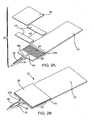
- Figs. 2A and 2B illustrate another suitable embodiment of a biosensor/skin-piercing/fluid access device 30 which is also disclosed in copending U.S. Patent Application having Attorney Docket No. LIFE-035.
- Device 30 has a photometric/colorimetric biosensor configuration and a microneedle 32 integrated therewith.
- the colorimetric or photometric biosensor is generally made up of at least the following components: a support element or substrate 34 made of either an inert material, such as plastic, or a metal material, a matrix area 36 for receiving a sample, a reagent composition (not shown as a structural component) within matrix area 36 that typically includes one or more members of an analyte oxidation signal producing system, an air venting port (not shown) and a top layer 38 which covers at least matrix 36.
- top layer 38 may be a membrane containing a reagent composition impregnated therein while the matrix area 36 may or may not contain reagent composition.
- test strip 30 has a double-sided adhesive layer 40 situated between substrate 34 and membrane 38 to hold them together. Double-sided adhesive layer 40 has a cut-out portion 42 which corresponds to the area covered by matrix 36 and defines an area for deposition of the sampled physiological fluid and for the various members of the signal producing system.
- Microneedle 32 is formed with and extends from and in substantially the same plane as substrate 34 and has a space-defining configuration in the form of an opening 44 which extends transverse to a dimension, e.g. , width or thickness, of microneedle 32.
- opening 44 forms an open space within the tissue upon penetration of microneedle 32 into the skin.
- Such open space acts as a sample fluid collection reservoir wherein fluid released upon penetration is pooled within the space prior to transfer into the photometric/colorimetric cell.
- Biosensor device 30 hosts a sample fluid transfer or extraction pathway 46 having a distal end 46b which extends within a portion of microneedle 32 and terminates at a distal opening 48. At least a portion of the proximal end 46a of pathway 46 resides within the biosensor portion of device 30, specifically within matrix area 36. Pathway 48 is dimensioned so as to exert a capillary force on fluid within the pooling area defined by opening 44, and draws or wicks physiological sample to within matrix area 36. Extending laterally from proximal portion 46a of pathway 46 to within a portion or the entirety of matrix area 36 are sub-channels 50, which facilitate the filling of matrix area 36 with the sampled fluid.
- Fig. 3 illustrates another exemplary biosensor device 60, disclosed in EP-A-1 284,121 , which is suitable for use with the present invention.
- Device 60 has an electrochemical test strip configuration similar to device 2 of Figs. 1A and 1B , having a first electrode 62 with an associated inert substrate 64, a second electrode 66 with an associated inert substrate 68 and a spacer layer 70 there between which, collectively, form a reaction zone 72 having an appropriate redox reagent system.
- device 60 has a plurality of skin-piercing elements 74 extending from and in substantially the same plane as spacer layer 70.
- Skin-piercing elements 74 may be made of the same material as spacer layer 70 or of a different material. Skin-piercing elements 74 each have a fluid channel 76 which extends proximally into spacer layer 70 to reaction zone 72. Each fluid channel 76 is open to the outside environment along a substantial length of a first side 78 and a second side 80 of the respective skin-piercing element and terminates proximal to distal tip 82 of the skin-piercing element 74. Channels 76 are dimensioned to exert a capillary force for collecting and transferring physiological sample accessed by the skin-piercing element 74. While each skin-piercing element is illustrated having a single fluid pathway 76, a plurality of such pathways may be used in each skin-piercing element 74.
- the number of skin piercing structures may vary, typically ranging from about 1 to 5, usually from about 1 to 4 and more usually from about 1 to 3, where the number of piercing elements typically ranges from 1 to 2 in many embodiments.
- the angle of the single bend typically ranges from about 135° to 150° and more usually from about 140° to 145°.
- the length from the bend to the very tip of the elongated angular structures typically ranges from about 2.3 to 3.2 ⁇ m and more usually from about 2.6 to 3.0.
- the fluid flow pathways 96 have capillary dimensions that result in capillary flow of accessed physiological fluid from the distal openings 94 along the length of the flow pathway to the biosensor 98.
- the flow path is one that has capillary dimensions
- the flow path typically has a diameter at any point along its length in the range from about 80 to 150 ⁇ m.
- the flow path may be tubular or have some other configuration, e.g., one that provides for a cross-sectional shape that is a square, rectangle, oval, star, etc., where the configuration of the flow path is not critical so long as it provides for the desired capillary flow.
- Biosensor 98 typically is made up of a sensor chamber that includes a transducing means which produces a signal in response to the presence, and typically concentration of, analyte in physiological fluid present in the chamber.
- the chamber located at the proximal end of device 90 typically has a volume in the range from about 100 to 300 ⁇ L.
- the transducing means may be any convenient transducing means that is capable of generating a signal in response to the presence of analyte in fluid present in the chamber. While in the broadest sense the transducing means may produce a signal that is indicative of the presence of analyte, in many preferred embodiments, the transducing means is one that generates a signal that is proportional to the amount of analyte in the physiological fluid.
- Photometric transducing means of interest typically include one or more reagents of a signal producing system that produces a detectable product in proportion to the amount of analyte present in the chamber. The detectable product is then photometrically detected to provide for a detection of the presence of analyte, and typically a measurement of the concentration of analyte, that is present in the fluid inside the chamber.
- Photometric transduction means of interest that may be employed in such biosensor devices include, but are not limited to, those described in U.S. Patent Nos.
- Electrochemical transducing means of interest typically include an electrochemical cell that includes two electrodes and one or more reagents of signal producing system, where these elements work in concert to produce an electrical current in proportion to the amount of analyte present in the chamber. The generated electrical current provides for a detection of the presence of analyte, and typically a measurement of the concentration of, analyte that is present in the fluid inside the chamber.
- Electrochemical transduction means of interest that may be employed in the biosensor devices include, but are not limited to, those described in U.S. Patent Nos. 5,834,224 ; 5,942,102 ; and 5,972,199 ; as well as EP-A-1 067 384 , EP-A-1 254 365 and EP-A-1 252 514 .
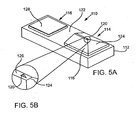
- Figs. 5A and 5B illustrate another biosensor/skin-piercing/fluid access device 110 not forming part of the present invention, which device is disclosed in the copending U.S. Patent Application the referenced above having Attorney Docket No. 058, herein incorporated by reference.
- Device 110 includes a planar frame 112, and a blade portion 114 and a sensor portion 116 mounted on and carried by frame 112.
- Blade portion 114 includes an intermediate wedge or raiser member 118 upon which is mounted a blade or lancing element 120 which extends substantially transverse to planar frame 112.
- Member 118 serves to elevate blade or lancing element 120 relative to a skin-facing surface or face 122 of frame 112.
- Raiser member 118 has an angled front surface or ramp portion 124 which allows for smooth translational movement of device 110 relative to the skin of the user.
- a landing area 126 is provided upon which blade 120 is specifically mounted, the narrow construct of which acts to reduce frictional forces with the user's skin while increasing the ability to compress tissue riding over the structure.
- Blade 120 is provided with a triangular shape having a larger base and substantially vertical side portions, however, blade 120 may have any shape whose geometry is robust enough to avoid break-off.
- Sensor portion 116 is spaced apart from blade portion 114 to allow substantially flush engagement by sensor portion 116 with the cut area of the user's skin.
- Sensor portion 116 provides a sensor pad or area 128 for receiving the access physiological fluid, i.e ., interstitial fluid or blood.
- Sensor pad 128 may have either an electrochemical or photometric configuration as described above.
- biosensor/skin-piercing/fluid access devices suitable for use with the systems of the present invention
- any type of biosensor e.g ., electrochemical, photometric, colorimetric
- any suitable shape of skin-piercing element may be employed with the biosensor devices, as long as the shape enables the skin to be pierced with minimal pain to the patient.
- the skin-piercing element may have a substantially flat or planar configuration, or may be substantially cylindrical-like, wedge-like or triangular in shape such as a substantially flattened triangle-like configuration, blade-shaped, or have any other suitable shape.
- the cross-sectional shape of the skin-piercing element, or at least the portion of skin-piercing element that is penetrable into the skin may be any suitable shape, including, but not limited to, substantially rectangular, oblong, square, oval, circular, diamond, triangular, star, etc.
- the skin-piercing element may be tapered or may otherwise define a point or apex at its distal end.
- Such a configuration may take the form of an oblique angle at the tip or a pyramid or triangular shape or the like.
- the dimensions of the skin-piercing element may vary depending on a variety of factors such as the type of physiological sample to be obtained, the desired penetration depth and the thickness of the skin layers of the particular patient being tested.
- the skin-piercing element is constructed to provide skin-piercing and fluid extraction functions and, thus, is designed to be sufficiently robust to withstand insertion into and withdrawal from the skin.
- biosensor/skin-piercing/fluid access devices are configured so as to provide a repeatable interface with the physiological fluid access site and with the target skin layer when operatively employed with the cartridge devices and systems of the present invention, which are now described in detail.
- a physiological sample collection and measurement system 200 of the present invention having a compact, portable structural configuration.
- This structure includes an ergonomic housing 202 having a top portion 204 and a bottom portion 206 hinged together by hinge means 208 which allows top and bottom portions 204 and 206 to be opened apart and closed upon manual activation of depressible key 226 or the like.
- Fig. 6D illustrates housing 202 in such an open condition while Figs. 6A, 6B and 6C illustrate housing 202 in a closed condition.
- top housing portion 204 and bottom housing portion 206 define an interior compartment into which a cartridge device 210 of the present invention is operatively loaded and then removed after use.
- cartridge 210 contains or provides one or more, and typically a plurality of, biosensor/fluid access devices 220.
- Such measurement means has the necessary construct and components for compatibility with the type of biosensor employed on devices 220, e.g ., an electrochemical, photometric or colorimetric sensor.
- the electrochemical measurement that is made may vary depending on the type of assay measurement and the meter employed, e.g ., depending on whether the assay is coulometric, amperometric or potentiometric.
- the electrochemical measurement will measure charge (coulometric), current (amperometric) or potential (potentiometric), usually over a given period of time following sample introduction into the reaction area.
- photometric/colorimetric assays optical-type meters are used to perform the assay.
- Such assays and methods and instruments for performing the same, are further described in U.S. Patent Nos.
- System 200 further includes means for operatively moving cartridge 210 within housing 202 so as to operatively move cartridge 210 in order to sequentially position each biosensor/fluid access device 220 at or relative to aperture 214.
- cartridge movement involves advancement of cartridge 210 in one direction, e.g ., clockwise, and reversal of cartridge 210 in the opposite direction, e.g ., counter clockwise, relative to aperture 214 to align a device 220 within aperture 214 and to remove or conceal a device 220 from aperture 214.
- Such cartridge movement means may be a motor-driven system, or the like, or may be manually driven by the user by means of a ring or lever mechanism external to housing 202.
- cartridge 210 may be provided with a drive wheel 232 such that, when cartridge device 210 is operatively loaded and positioned within housing 202, drive wheel 232 is engaged with a drive shaft 234 for rotating cartridge 210 in forward and reverse directions.
- Drive shaft 234 is in turn rotated by a drive motor, also located within compartment 230.
- System 200 also includes biosensor movement means (not shown) associated with cartridge 210 at aperture 214 for applying a force on each device 220 that is positioned at aperture 214.
- biosensor movement means moves a device 220 downward from the bottom surface of the cartridge on which all of the devices 220 are positioned, and through aperture 214 so as to operatively contact device 220 with the selected skin area.
- Such operative contact involves piercing, cutting or lancing the skin surface with a skin-piercing element provided on each device 220.
- Any convenient means for applying such downward force on a device 220 may be employed, where representative means include spring means or analogous mechanical means, and the like, which are described in greater detail below.
- System 200 further includes a controller having a microprocessor for controlling operation of the measurement means, data processing means, automated cartridge movement means, and a display 218 for displaying measurement data and other related data, e.g ., to inform the user when all of the devices 220 have been used.
- the microprocessor may further be associated with a memory storage means for the short-term or long-term storage of measurement data.
- System 200 may further include a communication module for the bidirectional communication with a remote control device or and other devices, e.g ., by wireless data communication means, e.g ., telemetry means, such as by infrared (IR) transmission or radio frequency (RF) transmission, for the communication of assay protocol programs and information and for the immediate or later retrieval of measurement data and the like.
- IR infrared
- RF radio frequency
- the system components just described may be housed in a protective, sealed compartment 230 wherein the necessary data or signal lines may run, for example, from compartment 230 in top housing portion 204 through hinge 208 to bottom housing portion 206. Alternately, such data or signal lines may be provided within top housing portion 204 such that they come into contact with corresponding data or signal lines within bottom housing portion 306 when the housing is in a closed condition.
- FIG. 7A there is shown a representation of one embodiment of a cartridge device 300 of the present invention suitable for use with at least the biosensor/skin-piercing/fluid access devices of Figs. 1 , 2 and 3 .
- Cartridge device 300 has a cartridge body or frame 302 and a plurality of integrated biosensor/skin-piercing/fluid access devices 304 (also referred to herein as biosensor devices) positioned thereon, preferably in a serial arrangement wherein devices 304 are evenly spaced apart from each other.
- the cartridges of the present invention may host any suitable number of integrated biosensor devices 304 wherein the number of cartridges generally ranges from about 6 to 10.
- cartridge body 302 is defined by concentric frame rings, outer frame ring 302a and inner frame ring 302b. Rings 302a and 302b are fixed relative to each other by means of a plurality of torsion bars 306 which extend between rings 302a and 302b.
- Frame 304 is made of any rigid material such as injection molded plastic such as a polycarbonate material, while torsion bars 306 are preferably made of a material having properties and/or dimensions so as to be flexible or twistable about their longitudinal axis, e.g ., stainless steel bars having a thickness in the range from about 50 to 75 ⁇ m and a width in the range from about 0.5 to 1 mm.
- Each integrated biosensor devices 304 is operatively attached to a torsion bar 306, preferably wherein there is a one-to-one correspondence between devices 304 and torsion bars 306.
- Each torsion bar 306 allows the corresponding attached device to rotate relative to frame 304 at least partially about the longitudinal axis defined by the torsion bar. As such, this axis of rotation is perpendicular to a path along which cartridge 300 is caused to rotate or travel.
- Cartridge 300 typically has a diameter ranging from about 3 to 4 cm, where the distance between the center of the disk and the biosensor devices typically ranges from about 7 to 9 mm.
- cartridge device 300 may further include a drive wheel 308 for attachment to a drive shaft housed within system 200 in which the cartridge device 300 is to be loaded.
- drive wheel 308 may also be separately housed within the system housing and be configured to receive and engage with cartridge frame 302.
- Drive wheel 308 includes a hub 310 and a plurality of frame bars 312 fixed to inner frame ring 302b. Rotation of drive wheel 308 causes rotational translation of cartridge body 302 and, thus, rotational translation of devices 304 about hub 310.
- biosensor movement component 320a has a top planar surface 322 and a downward sloping front surface 324, while biosensor movement component 320b has a top clip member 326 spring-loaded or biased against a bottom clip member 328.
- Component 320a is positioned on bottom housing portion 314 and under cartridge device 300 while component 320b is positioned such that the plane in which cartridge device 300 and biosensor devices 304 rotate passes between clip members 326 and 328.
- biosensor device 304a As device 304a is advanced, it is caused to wedge between top clip 326 and bottom clip 328b (see Fig. 8A ). As the clip members are biased against each other, biosensor device 304a is in frictional contact with component 320b when positioned between the clip members 326 and 328. When biosensor device 304a is sufficiently advanced in the direction of arrow 332 such that its back or proximal end 334 is between clip members 326 and 328, component 320b places a slight upward force or pressure on biosensor device 304a thereby causing device 304a to rotate about torsion bar 306 and front or needle end 336 of device 304a to deflect downward toward aperture 316 (see Fig. 8B ).
- deflected front end 336 is caused to contact sloped front surface 324 of wedged component 320a (see Fig. 8C ), thereby being further forced or deflected in a downward and forward direction.
- deflection and forward motion is sufficient to cause the skin-piercing element 340 of device 304a to pierce the target skin surface of the user (not shown).
- physiological fluid e.g ., interstitial fluid or blood
- the cartridge device 300 is caused to move in a reverse direction 342, e.g ., in a clockwise direction, (see Fig. 8D ) until device 304a becomes disengaged from movement components 320a and 320b and is caused by torsion bar 306 to return to its original planar position relative to cartridge rings 302a and 302b (see Fig. 8E ).
- cartridge 300 is again advanced in a forward direction 346 until used device 304a completely passes over aperture 316 of Fig. 7B (see Fig. 8F ), at which point cartridge 300 may be locked in place so as to prevent inadvertent movement and possible injury to the user.
- Such process is repeated with each device 304 when an assay protocol is activated by the user.
- the used cartridge may be removed from the system's housing and properly disposed of. A replacement cartridge may then be loaded into the system.
- the biosensor movement means 400 includes spaced-apart components 402a and 402b present within the housing of the subject systems. Components 402a and 402b are spaced apart so as to straddle an aperture 401 within the bottom housing wall, as described above, and provide surfaces and edges to guide a biosensor device 404 through aperture 401 for operatively contacting a target skin surface area of a user. Such surfaces and edges match the slope of the surfaces and the angles of the edges of biosensor device 404.
- biosensor device 404 may be operatively attached to a cartridge (not shown) by way of a tension bar (not shown) or by way of a rotational pivot attachment to a hub/spoke (see Figs. 10A-10C ) such that biosensor device 404 is held in an original biased position in which bottom surface 408 of device 404 is flush with top surface 406 of component 402b.
- a tension bar not shown
- a rotational pivot attachment to a hub/spoke
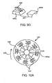
- FIG. 9B shows that as the angled biosensor 404 is moved across the spacing between components 402a and 402b in the direction of arrow 424, it drops down into the opening there between, moving along sloped surface 410 of component 402a.
- the direction of travel of angled biosensor 404 is reversed, as shown in Fig. 9C , in the forward direction indicated by arrow 426.
- angled biosensor 404 continues to move downward along sloped surface 410 such that bottom surface 408 of angled biosensor 404 becomes flush with a targeted skin surface exposed through aperture 401.
- biosensor 404 is again moved in the first direction as shown in Fig. 9E according to arrow 432.
- first direction reverse direction causes removal of biosensor 404 from the skin surface/sampling site and brings biosensor 404 up, out of the opening between components 402a and 402b, as shown in Fig. 9F and indicated by arrow 434.
- the angled sensor is brought out of the opening, as shown in Fig. 9G , the fluid present in the biosensor chamber can be assayed.
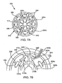
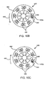
- rotary or disk cartridge 440 includes 8 individual angled biosensors 442 and is positioned on top of bottom surface 444 of housing (not shown) having an aperture 446 therein.
- cartridge 440 rotates in a first clockwise direction 448 as shown in Fig. 10A to operatively position a biosensor 442 relative to the biosensor movement means according to Figs. 9A and 9B .
- the direction of the cartridge rotation is then reversed to a counter-clockwise direction 450 as shown in Fig.
- the cartridge as well as the corresponding construct of the subject system may be configured in a number of different ways, so long as the cartridge device can be manipulated in a forward and reverse direction for performing the assay protocol, and as along as the biosensor devices can be operatively manipulated the biosensor movement means of the system so that the biosensor devices present on the cartridge can pierce the skin surface and access the physiological fluid therein.
- the device and systems may take a variety of different configurations.
- the devices are single integral devices, in which the measurement means, processing means, display means etc. are all present on the same structure.
- one or more of the components may be separate from the other components.
- the measurement means may be separated from the display means, where telemetric communication or analysis data transmission means, e.g ., radio frequency or RF means, are employed to provide for data communication between the two or more disparate components of the device.
- One representative subject system embodiment is a "watchband" embodiment as shown in Fig. 11A , in which the device 500 is configured to be worn around a limbic portion 502, e.g ., a forearm, in a manner analogous to a watch.
- a limbic portion 502 e.g ., a forearm
- all of the components of the device may be present in one integral unit, where the unit is maintained in contact with the skin of the host via an adjustable strap 504 or other retention means.
- a two component system may be employed.
- the cartridge device and measurement means i.e ., the biosensors and meter
- the display and control means are present on a second component of the system, e.g ., a hand-held, remote control unit 508.
- the two components communicate with each other a data communication means, where the data communication means is typically a wireless data communication means, e.g. , RF telemetric means.
- the subject systems do not require a band or strap for attachment, but instead, may be attached to an appropriate skin area by means of a biocompatible adhesive.
- a plurality of such integrated biosensor devices is provided in operative engagement with the cartridge device.
- the cartridge device is provided and positioned planar to a target skin surface area of the user.
- a movement means is employed to move or translate the cartridge in a first direction which acts to move or translate the biosensor device from an initial or retracted position to a second, extended or skin-contacting position wherein the target surface is pierced, physiological fluid is accessed and transported to the biosensor portion of the device.
- the movement means is then activated to move or translate the cartridge device in a second or reverse direction which acts to move or translate the biosensor from this second, extended position back to a retracted position.
- Such movement of the biosensor device from a retracted to a skin-contacting position, and visa versa, may be further defined by deflecting the biosensor device from a substantially planar position to angled or deflected position for contacting and piercing the skin.
- the cartridge device When used with the subject system as described above, the cartridge device is provided within or loaded into a housing structure having a skin-facing wall having an aperture therein.
- the external surface of the skin-facing wall is preferably positioned flush with the targeted skin surface area of the user.
- the cartridge device is positioned within housing structure such that it is planar with the skin facing surface and wherein the translation of the plurality of biosensor devices is in a pathway directly over the aperture.
- the movement or deflection of a particular biosensor device involves passage of at least the skin-piercing element through the aperture to contact and pierce the skin surface.
- the subject methods further include providing a meter or measurement means as described above in operative contact with the biosensor device for measuring the selected characteristic of the sampled physiological fluid transferred to the biosensor device upon accessing the physiological fluid.
- a signal is applied to the biosensor by the meter componentry of the subject system, and the chemical characteristic of interest, e.g ., analyte concentration, is made and the resulting measurement data is displayed via a display provided on the system housing and is stored into memory for immediate or later retrieval.
- the subject methods, devices and systems find use in a variety of different applications in which detection of an analyte and/or measurement of analyte concentration in a physiological fluid is desired.
- the subject systems, devices and methods find particular use in analyte concentration monitoring applications over a given period of time, as described in EP-A-1 260 815 , where the physiological fluid sampling/measurement occurs automatically and continuously according to a predetermined schedule.
- the present invention may be employed to: (a) continuously monitor an analyte whose concentration is associated with a disease condition, e.g ., hypo-or hyperglycemia in blood sugar disorders such as diabetes; (b) continuously monitor an analyte whose concentration is associated with a non-disease physiological condition of interest, e.g ., alcohol intoxication, illegal drug use; (c) continuously monitor the concentration of a therapeutic agent in drug therapy applications; etc.
- a disease condition e.g ., hypo-or hyperglycemia in blood sugar disorders such as diabetes
- a non-disease physiological condition of interest e.g ., alcohol intoxication, illegal drug use
- c continuously monitor the concentration of a therapeutic agent in drug therapy applications
- the present invention finds use in a variety of different applications relating to the treatment and management of glucose associated disease conditions, e.g ., diabetes and related conditions.
- the subject methods and devices find use in providing for "continual" glucose monitoring, by which is meant that glucose levels in a patient are measured intermittently and automatically according to a predetermined schedule.
- the subject methods can also be employed to detect and predict the occurrence of hypo- and hyperglycemic conditions.
- the pattern of continually monitored analyte concentration measurements can be employed to determine whether a patient is experiencing hyper- or hypoglycemia by comparing the pattern of measurement results stored within the systems memory storage means to a control or reference pattern.
- the subject methods can be part of a more comprehensive therapy protocol designed to prevent the occurrence of hypo and hyperglycemic events, e.g ., by predicting the occurrence of such events with the subject methods and device and intervening in blood sugar metabolism in a manner that prevents the occurrence of the predicted event.
- the present invention may be employed with a variety of different types of hosts where analyte monitoring is desired.
- Hosts of interest include, but are not limited to mammals. Mammals of interest include valuable livestock, e.g ., horses, cows, sheeps, etc., pets, e.g ., dogs, cats etc., and humans. In most embodiments, the mammals on which the subject methods are practiced are humans.
- kits for practicing the subject methods include a system for practicing the subject invention.
- the system may be a single integral device or made up of two or more disparate components, e.g. , a remote-control and display component and a measurement component.
- the kits may include a single disposable cartridge device, or two or more disposable cartridges devices, as described above for use with the subject system.
- the kits typically include instructions for using the subject systems and for loading and removing cartridges into and out of the subject system. These instructions may be present on one or more of the packaging, a label insert, containers present in the kits, and the like.
Landscapes
- Health & Medical Sciences (AREA)
- Life Sciences & Earth Sciences (AREA)
- Engineering & Computer Science (AREA)
- Physics & Mathematics (AREA)
- Medical Informatics (AREA)
- Animal Behavior & Ethology (AREA)
- Pathology (AREA)
- Hematology (AREA)
- Biomedical Technology (AREA)
- Heart & Thoracic Surgery (AREA)
- Veterinary Medicine (AREA)
- Molecular Biology (AREA)
- Surgery (AREA)
- Biophysics (AREA)
- General Health & Medical Sciences (AREA)
- Public Health (AREA)
- Manufacturing & Machinery (AREA)
- Dermatology (AREA)
- Diabetes (AREA)
- Geometry (AREA)
- Measurement Of The Respiration, Hearing Ability, Form, And Blood Characteristics Of Living Organisms (AREA)
- Investigating Or Analysing Biological Materials (AREA)
Claims (9)
- System, mit:einer Vielzahl von Vorrichtungen, wobei jede der Vorrichtungen aufweist:(i) wenigstens ein die Haut durchstechendes Element, das so gestaltet ist, dass es Zugriff auf physiologisches Fluid unterhalb der Hautoberfläche hat;(ii) einen Biosensor zum Messen einer Eigenschaft des physiologischen Fluides, auf das zugegriffen wurde, wobei das die Haut durchstechende Element mit dem Biosensor integriert ausgebildet ist; und(iii) einen Übertragungsweg für das physiologische Fluid, das sich von dem wenigstens einen die Haut durchstechenden Element zu dem Biosensor erstreckt; undeiner Einrichtung zum Bewegen jeder der Vielzahl von Vorrichtungen in einer Weise, die für das Durchdringen der Hautoberfläche durch das wenigstens eine die Haut durchstechende Element sorgt, gefolgt von Entfernen des wenigstens einen die Haut durchstechenden Elements von der Hautoberfläche; undeine Gehäusestruktur mit einer der Haut zugewandten Wand, die dazu konfiguriert ist, mit einem ausgewählten Bereich der Haut des Benutzers bündig zu sein, wobei die der Haut zugewandte Wand eine Öffnung umfasst,gekennzeichnet durcheine Kassette, die in der Gehäusestruktur aufnehmbar ist und eine Vielzahl von Torsionsstäben und eine Vielzahl von Vorrichtungen aufweist, wobei jede Vorrichtung auf einem jeweiligen der Torsionsstäbe drehbar befestigt ist, so dass sie in einer Richtung zur Öffnung hin drehbar ist, und wobei jede Vorrichtung in einer im Wesentlichen planaren Position bezüglich der der Haut zugewandten Wand gehalten wird,wobei die Einrichtung zum Bewegen ferner eine erste Komponente und eine zweite Komponente umfasst, die in dem Gehäuse funktionsfähig befestigt und nahe einer Vorderseite bzw. einer Rückseite der Öffnung positioniert sind,wobei die erste Komponente eine geneigte Fläche umfasst und die zweite Komponente ein Paar Klemmelemente umfasst, die gegeneinander vorgespannt sind,wobei die Einrichtung zum Bewegen eine Bewegung der Kassette innerhalb der Gehäusestruktur bewirkt, um so funktionsfähig jede der Vielzahl von Vorrichtungen relativ zu der Öffnung zu positionieren, so dass sie sich bei einem Vorwärtsbewegen einer Vorrichtung zwischen das Paar Klemmelemente keilt, wodurch verursacht wird, dass sie sich dreht und die geneigte Fläche der ersten Komponente berührt, wobei die Vorrichtung in einer Richtung nach unten und nach vorne abgelenkt wird, um zu verursachen, dass das die Haut durchstechende Element der Vorrichtung die Hautoberfläche in einem schrägen Winkel durchdringt.
- System nach Anspruch 1, bei dem jede der Vorrichtungen eine planare Struktur aufweist, wobei das wenigstens eine die Haut durchstechende Element sich von dieser erstreckt.
- System nach Anspruch 2, bei dem das wenigstens eine die Haut durchstechende Element sich im Wesentlichen in derselben Ebene wie die planare Struktur erstreckt.
- System nach Anspruch 3, bei dem die planare Vorrichtung einen Biosensor mit Ausgestaltung eines Teststreifens definiert und das wenigstens eine die Haut durchstechende Element sich von dem Teststreifen erstreckt.
- System nach Anspruch 1, das weiter aufweist:ein Messgerät, das innerhalb der Gehäusestruktur untergebracht ist, zum Aufgeben von Signalen an die Sensoreinrichtung zum Messen einer Eigenschaft des physiologischen Fluides und zum Empfangen von Signalen von der Sensoreinrichtung.
- System nach Anspruch 1, bei dem die Einrichtung zum Bewegen der Kassette jede der Vorrichtungen relativ zu der Öffnung in eine Richtung nach vorn und dann in eine umgekehrte Richtung bewegt.
- System nach Anspruch 1, weiter umfassend eine Einrichtung zum Steuern der Bewegung und der Zeitgebung der Bewegung der Kassette.
- System nach Anspruch 1, bei dem die Gehäusestruktur so ausgestaltet ist, dass sie auf einem Gliedmaßenbereich getragen werden kann.
- System nach Anspruch 1, bei dem die Gehäusestruktur so ausgestaltet ist, dass sie um die Hüfte getragen werden kann.
Priority Applications (1)
| Application Number | Priority Date | Filing Date | Title |
|---|---|---|---|
| DE60310159.3T DE60310159T3 (de) | 2002-05-09 | 2003-05-08 | Vorrichtung und Verfahren zur Zufuhr und Analyse von einer physiologischen Flüssigkeit |
Applications Claiming Priority (2)
| Application Number | Priority Date | Filing Date | Title |
|---|---|---|---|
| US10/143,253 US7343188B2 (en) | 2002-05-09 | 2002-05-09 | Devices and methods for accessing and analyzing physiological fluid |
| US143253 | 2002-05-09 |
Publications (3)
| Publication Number | Publication Date |
|---|---|
| EP1360934A1 EP1360934A1 (de) | 2003-11-12 |
| EP1360934B1 EP1360934B1 (de) | 2006-12-06 |
| EP1360934B2 true EP1360934B2 (de) | 2015-10-28 |
Family
ID=29249849
Family Applications (1)
| Application Number | Title | Priority Date | Filing Date |
|---|---|---|---|
| EP03252883.8A Expired - Lifetime EP1360934B2 (de) | 2002-05-09 | 2003-05-08 | Vorrichtung und Verfahren zur Zufuhr und Analyse von einer physiologischen Flüssigkeit |
Country Status (10)
| Country | Link |
|---|---|
| US (2) | US7343188B2 (de) |
| EP (1) | EP1360934B2 (de) |
| JP (1) | JP2004000598A (de) |
| CN (1) | CN1316247C (de) |
| AT (1) | ATE347306T1 (de) |
| CA (1) | CA2427843A1 (de) |
| DE (1) | DE60310159T3 (de) |
| IL (1) | IL155342A0 (de) |
| SG (1) | SG111106A1 (de) |
| TW (1) | TW200406174A (de) |
Families Citing this family (266)
| Publication number | Priority date | Publication date | Assignee | Title |
|---|---|---|---|---|
| US7899511B2 (en) | 2004-07-13 | 2011-03-01 | Dexcom, Inc. | Low oxygen in vivo analyte sensor |
| US9155496B2 (en) | 1997-03-04 | 2015-10-13 | Dexcom, Inc. | Low oxygen in vivo analyte sensor |
| US6036924A (en) | 1997-12-04 | 2000-03-14 | Hewlett-Packard Company | Cassette of lancet cartridges for sampling blood |
| US6391005B1 (en) | 1998-03-30 | 2002-05-21 | Agilent Technologies, Inc. | Apparatus and method for penetration with shaft having a sensor for sensing penetration depth |
| US8974386B2 (en) | 1998-04-30 | 2015-03-10 | Abbott Diabetes Care Inc. | Analyte monitoring device and methods of use |
| US6175752B1 (en) | 1998-04-30 | 2001-01-16 | Therasense, Inc. | Analyte monitoring device and methods of use |
| US6949816B2 (en) | 2003-04-21 | 2005-09-27 | Motorola, Inc. | Semiconductor component having first surface area for electrically coupling to a semiconductor chip and second surface area for electrically coupling to a substrate, and method of manufacturing same |
| US9066695B2 (en) | 1998-04-30 | 2015-06-30 | Abbott Diabetes Care Inc. | Analyte monitoring device and methods of use |
| US8346337B2 (en) | 1998-04-30 | 2013-01-01 | Abbott Diabetes Care Inc. | Analyte monitoring device and methods of use |
| US8480580B2 (en) | 1998-04-30 | 2013-07-09 | Abbott Diabetes Care Inc. | Analyte monitoring device and methods of use |
| US8688188B2 (en) | 1998-04-30 | 2014-04-01 | Abbott Diabetes Care Inc. | Analyte monitoring device and methods of use |
| US8465425B2 (en) | 1998-04-30 | 2013-06-18 | Abbott Diabetes Care Inc. | Analyte monitoring device and methods of use |
| US8641644B2 (en) | 2000-11-21 | 2014-02-04 | Sanofi-Aventis Deutschland Gmbh | Blood testing apparatus having a rotatable cartridge with multiple lancing elements and testing means |
| US6560471B1 (en) | 2001-01-02 | 2003-05-06 | Therasense, Inc. | Analyte monitoring device and methods of use |
| US7310543B2 (en) * | 2001-03-26 | 2007-12-18 | Kumetrix, Inc. | Silicon microprobe with integrated biosensor |
| AU2002348683A1 (en) | 2001-06-12 | 2002-12-23 | Pelikan Technologies, Inc. | Method and apparatus for lancet launching device integrated onto a blood-sampling cartridge |
| US7537571B2 (en) | 2001-06-12 | 2009-05-26 | Pelikan Technologies, Inc. | Integrated blood sampling analysis system with multi-use sampling module |
| WO2002100461A2 (en) | 2001-06-12 | 2002-12-19 | Pelikan Technologies, Inc. | Method and apparatus for improving success rate of blood yield from a fingerstick |
| US8337419B2 (en) | 2002-04-19 | 2012-12-25 | Sanofi-Aventis Deutschland Gmbh | Tissue penetration device |
| CA2448902C (en) | 2001-06-12 | 2010-09-07 | Pelikan Technologies, Inc. | Self optimizing lancing device with adaptation means to temporal variations in cutaneous properties |
| US7041068B2 (en) | 2001-06-12 | 2006-05-09 | Pelikan Technologies, Inc. | Sampling module device and method |
| US7981056B2 (en) | 2002-04-19 | 2011-07-19 | Pelikan Technologies, Inc. | Methods and apparatus for lancet actuation |
| WO2002100460A2 (en) | 2001-06-12 | 2002-12-19 | Pelikan Technologies, Inc. | Electric lancet actuator |
| US9226699B2 (en) | 2002-04-19 | 2016-01-05 | Sanofi-Aventis Deutschland Gmbh | Body fluid sampling module with a continuous compression tissue interface surface |
| US7682318B2 (en) | 2001-06-12 | 2010-03-23 | Pelikan Technologies, Inc. | Blood sampling apparatus and method |
| US9795747B2 (en) | 2010-06-02 | 2017-10-24 | Sanofi-Aventis Deutschland Gmbh | Methods and apparatus for lancet actuation |
| US7344507B2 (en) | 2002-04-19 | 2008-03-18 | Pelikan Technologies, Inc. | Method and apparatus for lancet actuation |
| US9427532B2 (en) | 2001-06-12 | 2016-08-30 | Sanofi-Aventis Deutschland Gmbh | Tissue penetration device |
| DE10134650B4 (de) | 2001-07-20 | 2009-12-03 | Roche Diagnostics Gmbh | System zur Entnahme kleiner Körperflüssigkeitsmengen |
| US7344894B2 (en) | 2001-10-16 | 2008-03-18 | Agilent Technologies, Inc. | Thermal regulation of fluidic samples within a diagnostic cartridge |
| US7004928B2 (en) | 2002-02-08 | 2006-02-28 | Rosedale Medical, Inc. | Autonomous, ambulatory analyte monitor or drug delivery device |
| US9282925B2 (en) | 2002-02-12 | 2016-03-15 | Dexcom, Inc. | Systems and methods for replacing signal artifacts in a glucose sensor data stream |
| US8260393B2 (en) | 2003-07-25 | 2012-09-04 | Dexcom, Inc. | Systems and methods for replacing signal data artifacts in a glucose sensor data stream |
| US8010174B2 (en) | 2003-08-22 | 2011-08-30 | Dexcom, Inc. | Systems and methods for replacing signal artifacts in a glucose sensor data stream |
| US9247901B2 (en) | 2003-08-22 | 2016-02-02 | Dexcom, Inc. | Systems and methods for replacing signal artifacts in a glucose sensor data stream |
| DE10208575C1 (de) | 2002-02-21 | 2003-08-14 | Hartmann Paul Ag | Blutanalysegerät zur Bestimmung eines Analyten |
| US9248267B2 (en) | 2002-04-19 | 2016-02-02 | Sanofi-Aventis Deustchland Gmbh | Tissue penetration device |
| US9314194B2 (en) | 2002-04-19 | 2016-04-19 | Sanofi-Aventis Deutschland Gmbh | Tissue penetration device |
| US7226461B2 (en) | 2002-04-19 | 2007-06-05 | Pelikan Technologies, Inc. | Method and apparatus for a multi-use body fluid sampling device with sterility barrier release |
| US8702624B2 (en) | 2006-09-29 | 2014-04-22 | Sanofi-Aventis Deutschland Gmbh | Analyte measurement device with a single shot actuator |
| US7485128B2 (en) | 2002-04-19 | 2009-02-03 | Pelikan Technologies, Inc. | Method and apparatus for penetrating tissue |
| US9795334B2 (en) | 2002-04-19 | 2017-10-24 | Sanofi-Aventis Deutschland Gmbh | Method and apparatus for penetrating tissue |
| US8267870B2 (en) | 2002-04-19 | 2012-09-18 | Sanofi-Aventis Deutschland Gmbh | Method and apparatus for body fluid sampling with hybrid actuation |
| US7648468B2 (en) * | 2002-04-19 | 2010-01-19 | Pelikon Technologies, Inc. | Method and apparatus for penetrating tissue |
| US7244265B2 (en) | 2002-04-19 | 2007-07-17 | Pelikan Technologies, Inc. | Method and apparatus for penetrating tissue |
| US7717863B2 (en) | 2002-04-19 | 2010-05-18 | Pelikan Technologies, Inc. | Method and apparatus for penetrating tissue |
| US7892183B2 (en) | 2002-04-19 | 2011-02-22 | Pelikan Technologies, Inc. | Method and apparatus for body fluid sampling and analyte sensing |
| US7909778B2 (en) | 2002-04-19 | 2011-03-22 | Pelikan Technologies, Inc. | Method and apparatus for penetrating tissue |
| US7141058B2 (en) | 2002-04-19 | 2006-11-28 | Pelikan Technologies, Inc. | Method and apparatus for a body fluid sampling device using illumination |
| US7291117B2 (en) | 2002-04-19 | 2007-11-06 | Pelikan Technologies, Inc. | Method and apparatus for penetrating tissue |
| US7524293B2 (en) | 2002-04-19 | 2009-04-28 | Pelikan Technologies, Inc. | Method and apparatus for penetrating tissue |
| US7491178B2 (en) | 2002-04-19 | 2009-02-17 | Pelikan Technologies, Inc. | Method and apparatus for penetrating tissue |
| US7563232B2 (en) | 2002-04-19 | 2009-07-21 | Pelikan Technologies, Inc. | Method and apparatus for penetrating tissue |
| US7892185B2 (en) | 2002-04-19 | 2011-02-22 | Pelikan Technologies, Inc. | Method and apparatus for body fluid sampling and analyte sensing |
| US7374544B2 (en) | 2002-04-19 | 2008-05-20 | Pelikan Technologies, Inc. | Method and apparatus for penetrating tissue |
| US8360992B2 (en) | 2002-04-19 | 2013-01-29 | Sanofi-Aventis Deutschland Gmbh | Method and apparatus for penetrating tissue |
| US8579831B2 (en) | 2002-04-19 | 2013-11-12 | Sanofi-Aventis Deutschland Gmbh | Method and apparatus for penetrating tissue |
| US7547287B2 (en) | 2002-04-19 | 2009-06-16 | Pelikan Technologies, Inc. | Method and apparatus for penetrating tissue |
| US7232451B2 (en) | 2002-04-19 | 2007-06-19 | Pelikan Technologies, Inc. | Method and apparatus for penetrating tissue |
| US7229458B2 (en) | 2002-04-19 | 2007-06-12 | Pelikan Technologies, Inc. | Method and apparatus for penetrating tissue |
| AU2003231749A1 (en) | 2002-04-19 | 2003-11-03 | Pelikan Technologies, Inc. | Device and method for variable speed lancet |
| US7976476B2 (en) | 2002-04-19 | 2011-07-12 | Pelikan Technologies, Inc. | Device and method for variable speed lancet |
| US7410468B2 (en) | 2002-04-19 | 2008-08-12 | Pelikan Technologies, Inc. | Method and apparatus for penetrating tissue |
| US7331931B2 (en) | 2002-04-19 | 2008-02-19 | Pelikan Technologies, Inc. | Method and apparatus for penetrating tissue |
| US8784335B2 (en) | 2002-04-19 | 2014-07-22 | Sanofi-Aventis Deutschland Gmbh | Body fluid sampling device with a capacitive sensor |
| US7371247B2 (en) | 2002-04-19 | 2008-05-13 | Pelikan Technologies, Inc | Method and apparatus for penetrating tissue |
| US8221334B2 (en) | 2002-04-19 | 2012-07-17 | Sanofi-Aventis Deutschland Gmbh | Method and apparatus for penetrating tissue |
| US7901362B2 (en) | 2002-04-19 | 2011-03-08 | Pelikan Technologies, Inc. | Method and apparatus for penetrating tissue |
| US7297122B2 (en) | 2002-04-19 | 2007-11-20 | Pelikan Technologies, Inc. | Method and apparatus for penetrating tissue |
| US7674232B2 (en) | 2002-04-19 | 2010-03-09 | Pelikan Technologies, Inc. | Method and apparatus for penetrating tissue |
| US7343188B2 (en) * | 2002-05-09 | 2008-03-11 | Lifescan, Inc. | Devices and methods for accessing and analyzing physiological fluid |
| US7399401B2 (en) * | 2002-10-09 | 2008-07-15 | Abbott Diabetes Care, Inc. | Methods for use in assessing a flow condition of a fluid |
| EP1552146B1 (de) | 2002-10-09 | 2011-04-20 | Abbott Diabetes Care Inc. | Kraftstoffzufuhrvorrichtung, system und verfahren |
| US7727181B2 (en) | 2002-10-09 | 2010-06-01 | Abbott Diabetes Care Inc. | Fluid delivery device with autocalibration |
| US7993108B2 (en) | 2002-10-09 | 2011-08-09 | Abbott Diabetes Care Inc. | Variable volume, shape memory actuated insulin dispensing pump |
| US20050049522A1 (en) * | 2002-10-30 | 2005-03-03 | Allen John J | Method of lancing skin for the extraction of blood |
| US8672852B2 (en) | 2002-12-13 | 2014-03-18 | Intercure Ltd. | Apparatus and method for beneficial modification of biorhythmic activity |
| US7815579B2 (en) * | 2005-03-02 | 2010-10-19 | Roche Diagnostics Operations, Inc. | Dynamic integrated lancing test strip with sterility cover |
| US8574895B2 (en) | 2002-12-30 | 2013-11-05 | Sanofi-Aventis Deutschland Gmbh | Method and apparatus using optical techniques to measure analyte levels |
| US7214200B2 (en) | 2002-12-30 | 2007-05-08 | Roche Diagnostics Operations, Inc. | Integrated analytical test element |
| DE10302501A1 (de) * | 2003-01-23 | 2004-08-05 | Roche Diagnostics Gmbh | Vorrichtung und Verfahren zur Aufnahme einer Körperflüssigkeit für Analysezwecke |
| US7052652B2 (en) | 2003-03-24 | 2006-05-30 | Rosedale Medical, Inc. | Analyte concentration detection devices and methods |
| US7473264B2 (en) * | 2003-03-28 | 2009-01-06 | Lifescan, Inc. | Integrated lance and strip for analyte measurement |
| US20040193072A1 (en) * | 2003-03-28 | 2004-09-30 | Allen John J. | Method of analyte measurement using integrated lance and strip |
| AU2004231988B2 (en) * | 2003-04-16 | 2010-04-15 | Drexel University | Acoustic blood analyzer for assessing blood properties |
| US7679407B2 (en) * | 2003-04-28 | 2010-03-16 | Abbott Diabetes Care Inc. | Method and apparatus for providing peak detection circuitry for data communication systems |
| EP2238892A3 (de) | 2003-05-30 | 2011-02-09 | Pelikan Technologies Inc. | Vorrichtung zur Entnahme von Körperflüssigkeit |
| ES2490740T3 (es) | 2003-06-06 | 2014-09-04 | Sanofi-Aventis Deutschland Gmbh | Aparato para toma de muestras de fluido sanguíneo y detección de analitos |
| WO2006001797A1 (en) | 2004-06-14 | 2006-01-05 | Pelikan Technologies, Inc. | Low pain penetrating |
| US7604592B2 (en) | 2003-06-13 | 2009-10-20 | Pelikan Technologies, Inc. | Method and apparatus for a point of care device |
| EP1529488A1 (de) | 2003-06-27 | 2005-05-11 | Ehrfeld Mikrotechnik AG | Vorrichtung und Verfahren zur Probenahme und Analyse von Körperflüssigkeiten |
| US7220034B2 (en) * | 2003-07-11 | 2007-05-22 | Rudolph Technologies, Inc. | Fiber optic darkfield ring light |
| US8423113B2 (en) | 2003-07-25 | 2013-04-16 | Dexcom, Inc. | Systems and methods for processing sensor data |
| US7761130B2 (en) | 2003-07-25 | 2010-07-20 | Dexcom, Inc. | Dual electrode system for a continuous analyte sensor |
| US8275437B2 (en) | 2003-08-01 | 2012-09-25 | Dexcom, Inc. | Transcutaneous analyte sensor |
| US7778680B2 (en) | 2003-08-01 | 2010-08-17 | Dexcom, Inc. | System and methods for processing analyte sensor data |
| US7591801B2 (en) | 2004-02-26 | 2009-09-22 | Dexcom, Inc. | Integrated delivery device for continuous glucose sensor |
| US9135402B2 (en) | 2007-12-17 | 2015-09-15 | Dexcom, Inc. | Systems and methods for processing sensor data |
| US20100168542A1 (en) | 2003-08-01 | 2010-07-01 | Dexcom, Inc. | System and methods for processing analyte sensor data |
| US20190357827A1 (en) | 2003-08-01 | 2019-11-28 | Dexcom, Inc. | Analyte sensor |
| US8761856B2 (en) | 2003-08-01 | 2014-06-24 | Dexcom, Inc. | System and methods for processing analyte sensor data |
| US7519408B2 (en) * | 2003-11-19 | 2009-04-14 | Dexcom, Inc. | Integrated receiver for continuous analyte sensor |
| US8369919B2 (en) | 2003-08-01 | 2013-02-05 | Dexcom, Inc. | Systems and methods for processing sensor data |
| US7494465B2 (en) | 2004-07-13 | 2009-02-24 | Dexcom, Inc. | Transcutaneous analyte sensor |
| US8845536B2 (en) | 2003-08-01 | 2014-09-30 | Dexcom, Inc. | Transcutaneous analyte sensor |
| US7925321B2 (en) | 2003-08-01 | 2011-04-12 | Dexcom, Inc. | System and methods for processing analyte sensor data |
| US8886273B2 (en) | 2003-08-01 | 2014-11-11 | Dexcom, Inc. | Analyte sensor |
| US7774145B2 (en) | 2003-08-01 | 2010-08-10 | Dexcom, Inc. | Transcutaneous analyte sensor |
| US8160669B2 (en) | 2003-08-01 | 2012-04-17 | Dexcom, Inc. | Transcutaneous analyte sensor |
| US7223248B2 (en) * | 2003-08-13 | 2007-05-29 | Lifescan, Inc. | Packaged medical device with a deployable dermal tissue penetration member |
| US7920906B2 (en) | 2005-03-10 | 2011-04-05 | Dexcom, Inc. | System and methods for processing analyte sensor data for sensor calibration |
| US8233959B2 (en) | 2003-08-22 | 2012-07-31 | Dexcom, Inc. | Systems and methods for processing analyte sensor data |
| US20140121989A1 (en) | 2003-08-22 | 2014-05-01 | Dexcom, Inc. | Systems and methods for processing analyte sensor data |
| EP1671096A4 (de) | 2003-09-29 | 2009-09-16 | Pelikan Technologies Inc | Verfahren und apparatur für eine verbesserte probeneinfangvorrichtung |
| EP1680014A4 (de) | 2003-10-14 | 2009-01-21 | Pelikan Technologies Inc | Verfahren und gerät für eine variable anwenderschnittstelle |
| WO2009067269A1 (en) | 2007-01-12 | 2009-05-28 | Facet Technologies, Llc | Multi-lancet cartridge and lancing device |
| US9247900B2 (en) | 2004-07-13 | 2016-02-02 | Dexcom, Inc. | Analyte sensor |
| US8287453B2 (en) | 2003-12-05 | 2012-10-16 | Dexcom, Inc. | Analyte sensor |
| US8364231B2 (en) | 2006-10-04 | 2013-01-29 | Dexcom, Inc. | Analyte sensor |
| US11633133B2 (en) | 2003-12-05 | 2023-04-25 | Dexcom, Inc. | Dual electrode system for a continuous analyte sensor |
| US8774886B2 (en) | 2006-10-04 | 2014-07-08 | Dexcom, Inc. | Analyte sensor |
| US8423114B2 (en) | 2006-10-04 | 2013-04-16 | Dexcom, Inc. | Dual electrode system for a continuous analyte sensor |
| EP2239567B1 (de) | 2003-12-05 | 2015-09-02 | DexCom, Inc. | Kalibrierverfahren für einen kontinuierlichen Analytsensor |
| EP2316331B1 (de) | 2003-12-09 | 2016-06-29 | Dexcom, Inc. | Signalverarbeitung in einem durchgehenden Analytsensor |
| JP4482318B2 (ja) * | 2003-12-15 | 2010-06-16 | パナソニック株式会社 | 穿刺針カートリッジ |
| WO2005065414A2 (en) | 2003-12-31 | 2005-07-21 | Pelikan Technologies, Inc. | Method and apparatus for improving fluidic flow and sample capture |
| US7822454B1 (en) | 2005-01-03 | 2010-10-26 | Pelikan Technologies, Inc. | Fluid sampling device with improved analyte detecting member configuration |
| US20050187525A1 (en) * | 2004-02-19 | 2005-08-25 | Hilgers Michael E. | Devices and methods for extracting bodily fluid |
| US8808228B2 (en) | 2004-02-26 | 2014-08-19 | Dexcom, Inc. | Integrated medicament delivery device for use with continuous analyte sensor |
| US7819822B2 (en) | 2004-03-06 | 2010-10-26 | Roche Diagnostics Operations, Inc. | Body fluid sampling device |
| PL1722670T3 (pl) | 2004-03-06 | 2014-03-31 | Hoffmann La Roche | Urządzenie do pobierania próbki płynu ustrojowego |
| WO2005102168A1 (en) | 2004-04-16 | 2005-11-03 | Facet Technologies, Llc | Cap displacement mechanism for lancing device and multi-lancet cartridge |
| US8792955B2 (en) | 2004-05-03 | 2014-07-29 | Dexcom, Inc. | Transcutaneous analyte sensor |
| US8828203B2 (en) | 2004-05-20 | 2014-09-09 | Sanofi-Aventis Deutschland Gmbh | Printable hydrogels for biosensors |
| GB2414734B (en) * | 2004-06-01 | 2010-09-08 | Rosti As | Devices for retaining and presenting for use a plurality of components |
| EP1765194A4 (de) | 2004-06-03 | 2010-09-29 | Pelikan Technologies Inc | Verfahren und gerät für eine flüssigkeitsentnahmenvorrichtung |
| US9775553B2 (en) | 2004-06-03 | 2017-10-03 | Sanofi-Aventis Deutschland Gmbh | Method and apparatus for a fluid sampling device |
| US20050284773A1 (en) * | 2004-06-29 | 2005-12-29 | Allen John J | Method of preventing reuse in an analyte measuring system |
| US8343074B2 (en) | 2004-06-30 | 2013-01-01 | Lifescan Scotland Limited | Fluid handling devices |
| US20060002817A1 (en) * | 2004-06-30 | 2006-01-05 | Sebastian Bohm | Flow modulation devices |
| US20060000709A1 (en) * | 2004-06-30 | 2006-01-05 | Sebastian Bohm | Methods for modulation of flow in a flow pathway |
| EP1804663A4 (de) * | 2004-06-30 | 2015-05-20 | Facet Technologies Llc | Lanzettenvorrichtung und multilanzettenkartusche |
| US8565848B2 (en) | 2004-07-13 | 2013-10-22 | Dexcom, Inc. | Transcutaneous analyte sensor |
| US7783333B2 (en) | 2004-07-13 | 2010-08-24 | Dexcom, Inc. | Transcutaneous medical device with variable stiffness |
| US7857760B2 (en) | 2004-07-13 | 2010-12-28 | Dexcom, Inc. | Analyte sensor |
| US8452368B2 (en) | 2004-07-13 | 2013-05-28 | Dexcom, Inc. | Transcutaneous analyte sensor |
| WO2006127694A2 (en) | 2004-07-13 | 2006-11-30 | Dexcom, Inc. | Analyte sensor |
| US8989833B2 (en) | 2004-07-13 | 2015-03-24 | Dexcom, Inc. | Transcutaneous analyte sensor |
| EP1671585A1 (de) * | 2004-12-17 | 2006-06-21 | F. Hoffmann-La Roche Ag | Verfahren zur Herstellung eines Stechelements |
| US20090054811A1 (en) * | 2004-12-30 | 2009-02-26 | Dirk Boecker | Method and apparatus for analyte measurement test time |
| US20060167382A1 (en) * | 2004-12-30 | 2006-07-27 | Ajay Deshmukh | Method and apparatus for storing an analyte sampling and measurement device |
| US8652831B2 (en) | 2004-12-30 | 2014-02-18 | Sanofi-Aventis Deutschland Gmbh | Method and apparatus for analyte measurement test time |
| US7545272B2 (en) | 2005-02-08 | 2009-06-09 | Therasense, Inc. | RF tag on test strips, test strip vials and boxes |
| US7935063B2 (en) | 2005-03-02 | 2011-05-03 | Roche Diagnostics Operations, Inc. | System and method for breaking a sterility seal to engage a lancet |
| US8133178B2 (en) | 2006-02-22 | 2012-03-13 | Dexcom, Inc. | Analyte sensor |
| US20090076360A1 (en) | 2007-09-13 | 2009-03-19 | Dexcom, Inc. | Transcutaneous analyte sensor |
| CN101180093B (zh) | 2005-03-21 | 2012-07-18 | 雅培糖尿病护理公司 | 用于提供结合的药剂输液以及分析物监测系统的方法和系统 |
| ATE509570T1 (de) * | 2005-03-24 | 2011-06-15 | Hoffmann La Roche | Analytisches hilfsmittel mit lanzette und testelement |
| EP1714613A1 (de) * | 2005-04-22 | 2006-10-25 | F. Hoffmann-La Roche Ag | Analytisches Hilfsmittel |
| US7768408B2 (en) | 2005-05-17 | 2010-08-03 | Abbott Diabetes Care Inc. | Method and system for providing data management in data monitoring system |
| US20080194516A1 (en) * | 2005-05-18 | 2008-08-14 | Flanders Samuel J | System for managing anti-coagulant infusions in patients |
| US20060281187A1 (en) | 2005-06-13 | 2006-12-14 | Rosedale Medical, Inc. | Analyte detection devices and methods with hematocrit/volume correction and feedback control |
| US7756561B2 (en) * | 2005-09-30 | 2010-07-13 | Abbott Diabetes Care Inc. | Method and apparatus for providing rechargeable power in data monitoring and management systems |
| US8801631B2 (en) | 2005-09-30 | 2014-08-12 | Intuity Medical, Inc. | Devices and methods for facilitating fluid transport |
| EP2559381B1 (de) * | 2005-09-30 | 2014-12-31 | Intuity Medical, Inc. | Vorrichtung für Körperflüssigkeitsprobennahme und -analyse |
| US7583190B2 (en) | 2005-10-31 | 2009-09-01 | Abbott Diabetes Care Inc. | Method and apparatus for providing data communication in data monitoring and management systems |
| US20080200838A1 (en) * | 2005-11-28 | 2008-08-21 | Daniel Goldberger | Wearable, programmable automated blood testing system |
| GB2433926A (en) * | 2005-12-22 | 2007-07-11 | Lifescan Scotland Inc | Container with RFID for storing calibration information |
| US9757061B2 (en) | 2006-01-17 | 2017-09-12 | Dexcom, Inc. | Low oxygen in vivo analyte sensor |
| EP1839576A1 (de) * | 2006-03-29 | 2007-10-03 | F.Hoffmann-La Roche Ag | Testsystem mit Testeinheit zum Untersuchen von Körperflüssigkeiten |
| US20080071158A1 (en) | 2006-06-07 | 2008-03-20 | Abbott Diabetes Care, Inc. | Analyte monitoring system and method |
| US8579853B2 (en) | 2006-10-31 | 2013-11-12 | Abbott Diabetes Care Inc. | Infusion devices and methods |
| EP1997429B1 (de) * | 2007-05-29 | 2011-11-23 | Roche Diagnostics GmbH | Flexible Lanzette in einem Lanzettensystem |
| US20080306434A1 (en) | 2007-06-08 | 2008-12-11 | Dexcom, Inc. | Integrated medicament delivery device for use with continuous analyte sensor |
| US9186097B2 (en) * | 2007-09-17 | 2015-11-17 | Roche Diabetes Care, Inc. | Body fluid lancing, acquiring, and testing cartridge design |
| US8961431B2 (en) * | 2009-09-28 | 2015-02-24 | Roche Diagnostics Operations, Inc. | Body fluid lancing, acquiring, and testing cartridge design |
| EP2227132B1 (de) | 2007-10-09 | 2023-03-08 | DexCom, Inc. | Integriertes insulin-abgabesystem mit kontinuierlichem glucosesensor |
| EP2050392B1 (de) * | 2007-10-15 | 2012-09-05 | Roche Diagnostics GmbH | Lanzettenrad |
| US8417312B2 (en) | 2007-10-25 | 2013-04-09 | Dexcom, Inc. | Systems and methods for processing sensor data |
| US9839395B2 (en) | 2007-12-17 | 2017-12-12 | Dexcom, Inc. | Systems and methods for processing sensor data |
| US20090209883A1 (en) * | 2008-01-17 | 2009-08-20 | Michael Higgins | Tissue penetrating apparatus |
| US8591455B2 (en) | 2008-02-21 | 2013-11-26 | Dexcom, Inc. | Systems and methods for customizing delivery of sensor data |
| JP2009225934A (ja) * | 2008-03-21 | 2009-10-08 | Nitto Denko Corp | 体液採取用回路基板およびバイオセンサ |
| US8396528B2 (en) | 2008-03-25 | 2013-03-12 | Dexcom, Inc. | Analyte sensor |
| EP2265324B1 (de) | 2008-04-11 | 2015-01-28 | Sanofi-Aventis Deutschland GmbH | Integriertes System zur Messung von Analyten |
| EP2113197A1 (de) * | 2008-05-03 | 2009-11-04 | Roche Diagnostics GmbH | Lanzettenrad und Verfahren zur Herstellung eines Lanzettenrades |
| EP2293719B1 (de) | 2008-05-30 | 2015-09-09 | Intuity Medical, Inc. | Schnittstelle zwischen einer Vorrichtung zur entnahme von Körperflüssigkeitsproben und der Entnahmestelle |
| US9636051B2 (en) | 2008-06-06 | 2017-05-02 | Intuity Medical, Inc. | Detection meter and mode of operation |
| JP2011522594A (ja) | 2008-06-06 | 2011-08-04 | インテュイティ メディカル インコーポレイテッド | 医用診断装置及び方法 |
| EP4227675B1 (de) | 2008-09-19 | 2024-12-11 | DexCom, Inc. | Partikelhaltige membran und partikelelektrode für analytsensoren |
| KR20110079701A (ko) * | 2008-09-30 | 2011-07-07 | 멘나이 메디컬 테크놀로지즈 리미티드 | 샘플 계측 시스템 |
| US9375169B2 (en) | 2009-01-30 | 2016-06-28 | Sanofi-Aventis Deutschland Gmbh | Cam drive for managing disposable penetrating member actions with a single motor and motor and control system |
| JP4885330B2 (ja) * | 2009-02-18 | 2012-02-29 | パナソニック株式会社 | 穿刺器具、生体試料測定装置及び生体試料測定システム |
| EP2226007A1 (de) | 2009-02-19 | 2010-09-08 | Roche Diagnostics GmbH | Testelementmagazin mit abgedeckten Testfeldern |
| EP2398388B1 (de) | 2009-02-19 | 2020-04-08 | Roche Diabetes Care GmbH | Platzsparende magazinierung analytischer hilfsmittel |
| EP2226008A1 (de) | 2009-02-19 | 2010-09-08 | Roche Diagnostics GmbH | Verfahren zur Herstellung eines analytischen Magazins |
| WO2010101625A2 (en) * | 2009-03-02 | 2010-09-10 | Seventh Sense Biosystems, Inc. | Oxygen sensor |
| WO2010101621A1 (en) | 2009-03-02 | 2010-09-10 | Seventh Sense Biosystems, Inc. | Devices and methods for the analysis of an extractable medium |
| US9033898B2 (en) | 2010-06-23 | 2015-05-19 | Seventh Sense Biosystems, Inc. | Sampling devices and methods involving relatively little pain |
| US9295417B2 (en) | 2011-04-29 | 2016-03-29 | Seventh Sense Biosystems, Inc. | Systems and methods for collecting fluid from a subject |
| US9446194B2 (en) | 2009-03-27 | 2016-09-20 | Dexcom, Inc. | Methods and systems for promoting glucose management |
| WO2010129375A1 (en) | 2009-04-28 | 2010-11-11 | Abbott Diabetes Care Inc. | Closed loop blood glucose control algorithm analysis |
| JP2010271259A (ja) * | 2009-05-25 | 2010-12-02 | Sysmex Corp | 生体成分分析方法、生体成分分析装置、生体成分分析用カートリッジおよび生体成分分析用キット |
| US9517027B2 (en) * | 2009-07-10 | 2016-12-13 | Facet Techonologies, Llc | Advancement mechanism for cartridge-based devices |
| EP2493535A2 (de) * | 2009-10-30 | 2012-09-05 | Seventh Sense Biosystems, Inc. | Systeme und verfahren zur anwendung auf der haut und zur steuerung ihrer betätigung, freisetzung und/oder wahrnehmung |
| CA2782047C (en) | 2009-11-30 | 2019-10-29 | Intuity Medical, Inc. | Calibration material delivery devices and methods |
| EP2523706B1 (de) * | 2010-01-13 | 2019-08-21 | Seventh Sense Biosystems, Inc. | Schnelle ausgabe und/oder entnahme von flüssigkeiten |
| WO2011094573A1 (en) | 2010-01-28 | 2011-08-04 | Seventh Sense Biosystems, Inc. | Monitoring or feedback systems and methods |
| GB201005359D0 (en) | 2010-03-30 | 2010-05-12 | Menai Medical Technologies Ltd | Sampling plate |
| GB201005357D0 (en) | 2010-03-30 | 2010-05-12 | Menai Medical Technologies Ltd | Sampling plate |
| US8965476B2 (en) * | 2010-04-16 | 2015-02-24 | Sanofi-Aventis Deutschland Gmbh | Tissue penetration device |
| WO2011162823A1 (en) | 2010-06-25 | 2011-12-29 | Intuity Medical, Inc. | Analyte monitoring methods and systems |
| TW201212887A (en) * | 2010-07-08 | 2012-04-01 | Sanofi Aventis Deutschland | Eliciting a blood sample |
| JP2013538069A (ja) | 2010-07-16 | 2013-10-10 | セブンス センス バイオシステムズ,インコーポレーテッド | 流体移動デバイスのための低圧環境 |
| US20130158482A1 (en) | 2010-07-26 | 2013-06-20 | Seventh Sense Biosystems, Inc. | Rapid delivery and/or receiving of fluids |
| US20120039809A1 (en) | 2010-08-13 | 2012-02-16 | Seventh Sense Biosystems, Inc. | Systems and techniques for monitoring subjects |
| JP5827999B2 (ja) * | 2010-10-06 | 2015-12-02 | プロフューザ,インコーポレイティド | 組織集積センサー |
| EP2637562B1 (de) | 2010-11-09 | 2016-01-27 | Seventh Sense Biosystems, Inc. | Systeme und schnittstellen zur blutabnahme |
| US9717452B2 (en) | 2010-12-30 | 2017-08-01 | Roche Diabetes Care, Inc. | Handheld medical diagnostic devices with lancing speed control |
| US8852123B2 (en) | 2010-12-30 | 2014-10-07 | Roche Diagnostics Operations, Inc. | Handheld medical diagnostic devices housing with sample transfer |
| US8158428B1 (en) | 2010-12-30 | 2012-04-17 | General Electric Company | Methods, systems and apparatus for detecting material defects in combustors of combustion turbine engines |
| US9848809B2 (en) | 2011-04-15 | 2017-12-26 | Dexcom, Inc. | Advanced analyte sensor calibration and error detection |
| EP2701600B1 (de) | 2011-04-29 | 2016-06-08 | Seventh Sense Biosystems, Inc. | Ausgabe und/oder aufnahme von flüssigkeiten |
| US20130158468A1 (en) | 2011-12-19 | 2013-06-20 | Seventh Sense Biosystems, Inc. | Delivering and/or receiving material with respect to a subject surface |
| JP2014516644A (ja) | 2011-04-29 | 2014-07-17 | セブンス センス バイオシステムズ,インコーポレーテッド | 血斑または他の体液の収集および/または操作のためのデバイスおよび方法 |
| EP2520225B1 (de) * | 2011-05-06 | 2014-05-21 | Roche Diagnostics GmbH | Lanzette |
| US9782114B2 (en) | 2011-08-03 | 2017-10-10 | Intuity Medical, Inc. | Devices and methods for body fluid sampling and analysis |
| CN104203098A (zh) * | 2012-01-10 | 2014-12-10 | 赛诺菲-安万特德国有限公司 | 电容传感器 |
| US20140371629A1 (en) * | 2012-01-10 | 2014-12-18 | Sanofi-Aventis Deutschland Gmbh | Apparatus for eliciting a blood sample |
| US9217723B2 (en) | 2012-03-02 | 2015-12-22 | Cilag Gmbh International | Co-facial analytical test strip with stacked unidirectional contact pads |
| US9931065B2 (en) | 2012-04-04 | 2018-04-03 | Dexcom, Inc. | Transcutaneous analyte sensors, applicators therefor, and associated methods |
| CA2860998C (en) * | 2012-04-16 | 2017-01-17 | F. Hoffmann-La Roche Ag | Methods and structures for assembling lancet housing assemblies for handheld medical diagnostic devices |
| JP6312670B2 (ja) * | 2012-07-23 | 2018-04-18 | タッソ インコーポレイテッド | 開放マイクロ流体チャンネルに関する方法、システムおよび装置 |
| US9119528B2 (en) | 2012-10-30 | 2015-09-01 | Dexcom, Inc. | Systems and methods for providing sensitive and specific alarms |
| US10375594B2 (en) * | 2013-02-12 | 2019-08-06 | Samsung Electronics Co., Ltd. | Apparatus and method for generating an alert based on signal strength |
| US10729386B2 (en) | 2013-06-21 | 2020-08-04 | Intuity Medical, Inc. | Analyte monitoring system with audible feedback |
| US9933387B1 (en) | 2014-09-07 | 2018-04-03 | Biolinq, Inc. | Miniaturized sub-nanoampere sensitivity low-noise potentiostat system |
| US10390707B2 (en) * | 2015-05-11 | 2019-08-27 | Samsung Electronics Co., Ltd | Needle for biosensor and bio sensor including the same |
| US10154809B2 (en) | 2015-06-24 | 2018-12-18 | University Of Virginia Patent Foundation | Test strip device and related methods thereof |
| CN108024716B (zh) | 2015-10-21 | 2022-04-29 | 德克斯康公司 | 经皮分析物传感器、其施加器以及相关联方法 |
| US10092207B1 (en) | 2016-05-15 | 2018-10-09 | Biolinq, Inc. | Tissue-penetrating electrochemical sensor featuring a co-electrodeposited thin film comprised of polymer and bio-recognition element |
| US12109032B1 (en) | 2017-03-11 | 2024-10-08 | Biolinq Incorporated | Methods for achieving an isolated electrical interface between an anterior surface of a microneedle structure and a posterior surface of a support structure |
| US11045142B1 (en) | 2017-04-29 | 2021-06-29 | Biolinq, Inc. | Heterogeneous integration of silicon-fabricated solid microneedle sensors and CMOS circuitry |
| CA3068815A1 (en) * | 2017-07-06 | 2019-01-10 | Becton, Dickinson And Company | Biological fluid collection device |
| US12599337B1 (en) | 2017-08-08 | 2026-04-14 | Biolinq Incorporated | Method and system for confirmation of microneedle-based analyte-selective sensor insertion into viable tissue via electrical interrogation |
| EP3928687B1 (de) | 2017-10-24 | 2024-06-26 | Dexcom, Inc. | Tragbare vorrichtung mit vorverbundenem analytsensor |
| US11331022B2 (en) | 2017-10-24 | 2022-05-17 | Dexcom, Inc. | Pre-connected analyte sensors |
| WO2019176324A1 (ja) * | 2018-03-13 | 2019-09-19 | Phcホールディングス株式会社 | センサ挿入装置 |
| USD875254S1 (en) | 2018-06-08 | 2020-02-11 | Biolinq, Inc. | Intradermal biosensor |
| US10973444B1 (en) * | 2018-07-31 | 2021-04-13 | Jeffrey Michaels | Standalone blood glucose meter |
| CN111150407A (zh) * | 2020-02-20 | 2020-05-15 | 苏州大学 | 可穿戴血糖仪 |
| US20220031244A1 (en) | 2020-07-29 | 2022-02-03 | Biolinq Inc. | Continuous analyte monitoring system with microneedle array |
| EP4256315A4 (de) | 2020-12-03 | 2024-11-06 | Biolinq Incorporated | Festkörpersubstratintegrierte referenzelektrode und gegenelektrode |
| WO2022164975A1 (en) * | 2021-01-29 | 2022-08-04 | Battelle Memorial Institute | Robot for bio-surveillance and bio-surveillance system |
| USD988160S1 (en) * | 2021-03-16 | 2023-06-06 | Biolinq Incorporated | Wearable dermal sensor |
| EP4153276B1 (de) | 2021-05-08 | 2025-12-10 | Biolinq Incorporated | Fehlererkennung für eine auf mikronadelarrays basierende kontinuierliche analytüberwachungsvorrichtung |
| WO2023003889A1 (en) * | 2021-07-19 | 2023-01-26 | Carnegie Mellon University | Scalable manufacturing of microneedle arrays using automated high-throughput manufacturing systems and high-capacity molding |
| USD1013544S1 (en) * | 2022-04-29 | 2024-02-06 | Biolinq Incorporated | Wearable sensor |
| USD996999S1 (en) * | 2021-11-16 | 2023-08-29 | Biolinq Incorporated | Wearable sensor |
| USD1012744S1 (en) * | 2022-05-16 | 2024-01-30 | Biolinq Incorporated | Wearable sensor with illuminated display |
| CN115656302B (zh) * | 2022-11-10 | 2025-10-28 | 云南中烟工业有限责任公司 | 一种活体原位检测烟叶中关键成分的装置 |
| EP4658168A2 (de) | 2023-02-02 | 2025-12-10 | Biolinq, Inc. | Verfahren zur verbesserten sensorempfindlichkeit eines kontinuierlichen analytüberwachungssystems auf mikronadelbasis |
| USD1068516S1 (en) * | 2023-02-28 | 2025-04-01 | Biolinq Incorporated | Wearable sensor |
| USD1083977S1 (en) | 2023-02-28 | 2025-07-15 | Biolinq Incorporated | Display with graphical user interface for a wearable sensor |
| USD1035004S1 (en) | 2023-02-28 | 2024-07-09 | Biolinq Incorporated | Wearable sensor |
| USD1083640S1 (en) | 2023-05-16 | 2025-07-15 | Biolinq Incorporated | Wearable sensor |
Family Cites Families (60)
| Publication number | Priority date | Publication date | Assignee | Title |
|---|---|---|---|---|
| US3589557A (en) * | 1969-04-03 | 1971-06-29 | Miles Lab | Slide dispenser |
| JPS5912135B2 (ja) * | 1977-09-28 | 1984-03-21 | 松下電器産業株式会社 | 酵素電極 |
| DE2803345C2 (de) | 1978-01-26 | 1980-02-14 | Emil 7507 Pfinztal Eisinger | Blutprobenentnahmegerät |
| US4187077A (en) * | 1978-06-05 | 1980-02-05 | Eastman Kodak Company | Container with article positioning element for dispensing reagent coated slides to an automated analyzer |
| DE3278334D1 (en) * | 1981-10-23 | 1988-05-19 | Genetics Int Inc | Sensor for components of a liquid mixture |
| US4734360A (en) * | 1983-07-12 | 1988-03-29 | Lifescan, Inc. | Colorimetric ethanol analysis method and test device |
| US4900666A (en) * | 1983-07-12 | 1990-02-13 | Lifescan, Inc. | Colorimetric ethanol analysis method and test device |
| US4787398A (en) * | 1985-04-08 | 1988-11-29 | Garid, Inc. | Glucose medical monitoring system |
| US4627445A (en) * | 1985-04-08 | 1986-12-09 | Garid, Inc. | Glucose medical monitoring system |
| IL80628A0 (en) * | 1985-11-18 | 1987-02-27 | Bajada Serge | Apparatus for testing the sensory system in humans or animals |
| US5059394A (en) * | 1986-08-13 | 1991-10-22 | Lifescan, Inc. | Analytical device for the automated determination of analytes in fluids |
| US4935346A (en) | 1986-08-13 | 1990-06-19 | Lifescan, Inc. | Minimum procedure system for the determination of analytes |
| US5049487A (en) * | 1986-08-13 | 1991-09-17 | Lifescan, Inc. | Automated initiation of timing of reflectance readings |
| US4794926A (en) * | 1986-11-24 | 1989-01-03 | Invictus, Inc. | Lancet cartridge |
| US4924879A (en) * | 1988-10-07 | 1990-05-15 | Brien Walter J O | Blood lancet device |
| US5620863A (en) * | 1989-08-28 | 1997-04-15 | Lifescan, Inc. | Blood glucose strip having reduced side reactions |
| AU640162B2 (en) * | 1989-08-28 | 1993-08-19 | Lifescan, Inc. | Blood separation and analyte detection techniques |
| US5306623A (en) * | 1989-08-28 | 1994-04-26 | Lifescan, Inc. | Visual blood glucose concentration test strip |
| JPH0820412B2 (ja) * | 1990-07-20 | 1996-03-04 | 松下電器産業株式会社 | 使い捨てセンサを用いた定量分析方法、及び装置 |
| US5376668A (en) * | 1990-08-21 | 1994-12-27 | Novo Nordisk A/S | Heterocyclic compounds |
| GR1002549B (el) * | 1992-05-12 | 1997-01-28 | Lifescan Inc. | Λωρις εξετασεως με μεταφορικο μεσο δια μεταφορα ρευστου. |
| US5509394A (en) * | 1993-02-03 | 1996-04-23 | Mazda Motor Corporation | Internal combustion engine with supercharger |
| DE59410388D1 (de) * | 1993-04-23 | 2004-10-21 | Roche Diagnostics Gmbh | Diskette mit kreisförmig angeordneten Testelementen |
| US5843691A (en) * | 1993-05-15 | 1998-12-01 | Lifescan, Inc. | Visually-readable reagent test strip |
| DE4430023A1 (de) * | 1994-08-24 | 1996-02-29 | Boehringer Mannheim Gmbh | Elektrochemischer Sensor |
| US5515170A (en) * | 1994-09-08 | 1996-05-07 | Lifescan, Inc. | Analyte detection device having a serpentine passageway for indicator strips |
| KR100354581B1 (ko) * | 1994-09-08 | 2003-02-11 | 라이프스캔, 인코포레이티드 | 광판독스트립 |
| US5526120A (en) * | 1994-09-08 | 1996-06-11 | Lifescan, Inc. | Test strip with an asymmetrical end insuring correct insertion for measuring |
| US5575403A (en) * | 1995-01-13 | 1996-11-19 | Bayer Corporation | Dispensing instrument for fluid monitoring sensors |
| FR2733745B1 (fr) * | 1995-05-02 | 1997-07-04 | Asulab Sa | Appareil perfectionne destine a la ditribution de zones successives d'une bande consommable |
| US5510266A (en) * | 1995-05-05 | 1996-04-23 | Bayer Corporation | Method and apparatus of handling multiple sensors in a glucose monitoring instrument system |
| US5972199A (en) * | 1995-10-11 | 1999-10-26 | E. Heller & Company | Electrochemical analyte sensors using thermostable peroxidase |
| AU722471B2 (en) * | 1995-10-17 | 2000-08-03 | Lifescan, Inc. | Blood glucose strip having reduced sensitivity to hematocrit |
| US5759010A (en) * | 1995-11-06 | 1998-06-02 | Jacobs; Merrit Nyles | Sealed cartridge to improve chemistry stability of test elements |
| AUPN661995A0 (en) * | 1995-11-16 | 1995-12-07 | Memtec America Corporation | Electrochemical cell 2 |
| US5801057A (en) * | 1996-03-22 | 1998-09-01 | Smart; Wilson H. | Microsampling device and method of construction |
| IL120587A (en) * | 1996-04-04 | 2000-10-31 | Lifescan Inc | Reagent test strip for determination of blood glucose |
| US5660791A (en) * | 1996-06-06 | 1997-08-26 | Bayer Corporation | Fluid testing sensor for use in dispensing instrument |
| US5846486A (en) * | 1996-08-09 | 1998-12-08 | Lifescan, Inc. | Hollow frustum reagent test device |
| US5753429A (en) * | 1996-08-09 | 1998-05-19 | Lifescan, Inc. | Analyte concentration measurement using a hollow frustum |
| US6071251A (en) * | 1996-12-06 | 2000-06-06 | Abbott Laboratories | Method and apparatus for obtaining blood for diagnostic tests |
| US5971941A (en) * | 1997-12-04 | 1999-10-26 | Hewlett-Packard Company | Integrated system and method for sampling blood and analysis |
| US6036924A (en) * | 1997-12-04 | 2000-03-14 | Hewlett-Packard Company | Cassette of lancet cartridges for sampling blood |
| DE19819407A1 (de) | 1998-04-30 | 1999-11-11 | Hendrik Priebs | Teststreifenbehälter für Messgeräte, die mit Einwegteststreifen arbeiten |
| DE19840856B4 (de) | 1998-09-07 | 2008-04-10 | Roche Diagnostics Gmbh | System zur Gewinnung einer Köperflüssigkeit, Lanzettenmagazin, Lanzette, Lanzettensatz, Stechhilfe und Verfahren zur Entnahme einer Lanzette aus einem Lanzettenmagazin sowie Verwendung des Systems |
| US6475372B1 (en) | 2000-02-02 | 2002-11-05 | Lifescan, Inc. | Electrochemical methods and devices for use in the determination of hematocrit corrected analyte concentrations |
| US6193873B1 (en) * | 1999-06-15 | 2001-02-27 | Lifescan, Inc. | Sample detection to initiate timing of an electrochemical assay |
| EP1216416B1 (de) | 1999-09-27 | 2006-02-15 | Hypoguard Limited | Prüfvorrichtung |
| US6228100B1 (en) * | 1999-10-25 | 2001-05-08 | Steven Schraga | Multi-use lancet device |
| US6716577B1 (en) | 2000-02-02 | 2004-04-06 | Lifescan, Inc. | Electrochemical test strip for use in analyte determination |
| AU2001234137A1 (en) | 2000-02-23 | 2001-09-03 | Arkray, Inc. | Sensor cartridge, sensor feeder, and measuring instrument |
| US6706159B2 (en) | 2000-03-02 | 2004-03-16 | Diabetes Diagnostics | Combined lancet and electrochemical analyte-testing apparatus |
| US6612111B1 (en) | 2000-03-27 | 2003-09-02 | Lifescan, Inc. | Method and device for sampling and analyzing interstitial fluid and whole blood samples |
| US6540675B2 (en) * | 2000-06-27 | 2003-04-01 | Rosedale Medical, Inc. | Analyte monitor |
| GB0030929D0 (en) | 2000-12-19 | 2001-01-31 | Inverness Medical Ltd | Analyte measurement |
| US6530892B1 (en) * | 2001-03-07 | 2003-03-11 | Helen V. Kelly | Automatic skin puncturing system |
| US7310543B2 (en) * | 2001-03-26 | 2007-12-18 | Kumetrix, Inc. | Silicon microprobe with integrated biosensor |
| US20030028125A1 (en) * | 2001-08-06 | 2003-02-06 | Yuzhakov Vadim V. | Physiological sample collection devices and methods of using the same |
| US6952604B2 (en) * | 2001-12-21 | 2005-10-04 | Becton, Dickinson And Company | Minimally-invasive system and method for monitoring analyte levels |
| US7343188B2 (en) * | 2002-05-09 | 2008-03-11 | Lifescan, Inc. | Devices and methods for accessing and analyzing physiological fluid |
-
2002
- 2002-05-09 US US10/143,253 patent/US7343188B2/en not_active Expired - Fee Related
-
2003
- 2003-04-10 IL IL15534203A patent/IL155342A0/xx unknown
- 2003-04-25 SG SG200302555A patent/SG111106A1/en unknown
- 2003-05-05 CA CA002427843A patent/CA2427843A1/en not_active Abandoned
- 2003-05-07 CN CNB031309194A patent/CN1316247C/zh not_active Expired - Fee Related
- 2003-05-08 DE DE60310159.3T patent/DE60310159T3/de not_active Expired - Lifetime
- 2003-05-08 JP JP2003130374A patent/JP2004000598A/ja active Pending
- 2003-05-08 TW TW092112509A patent/TW200406174A/zh unknown
- 2003-05-08 AT AT03252883T patent/ATE347306T1/de not_active IP Right Cessation
- 2003-05-08 EP EP03252883.8A patent/EP1360934B2/de not_active Expired - Lifetime
-
2007
- 2007-09-20 US US11/858,642 patent/US20080009768A1/en not_active Abandoned
Also Published As
| Publication number | Publication date |
|---|---|
| SG111106A1 (en) | 2005-05-30 |
| DE60310159T3 (de) | 2016-03-10 |
| EP1360934A1 (de) | 2003-11-12 |
| JP2004000598A (ja) | 2004-01-08 |
| ATE347306T1 (de) | 2006-12-15 |
| CN1316247C (zh) | 2007-05-16 |
| US20080009768A1 (en) | 2008-01-10 |
| CA2427843A1 (en) | 2003-11-09 |
| US7343188B2 (en) | 2008-03-11 |
| EP1360934B1 (de) | 2006-12-06 |
| US20030212347A1 (en) | 2003-11-13 |
| CN1456887A (zh) | 2003-11-19 |
| IL155342A0 (en) | 2003-11-23 |
| TW200406174A (en) | 2004-05-01 |
| DE60310159T2 (de) | 2007-09-20 |
| DE60310159D1 (de) | 2007-01-18 |
| HK1057158A1 (en) | 2004-03-19 |
Similar Documents
| Publication | Publication Date | Title |
|---|---|---|
| EP1360934B1 (de) | Vorrichtung und Verfahren zur Zufuhr und Analyse von einer physiologischen Flüssigkeit | |
| AU2002247008B2 (en) | Lancet device having capillary action | |
| AU2001249100B2 (en) | Combined lancet and electrochemical analyte-testing apparatus | |
| EP1174078B1 (de) | Mikrohohlnadelpflaster | |
| US20080200838A1 (en) | Wearable, programmable automated blood testing system | |
| AU2001249100A1 (en) | Combined lancet and electrochemical analyte-testing apparatus | |
| AU2002247008A1 (en) | Lancet device having capillary action | |
| CA2623589A1 (en) | Catalysts for body fluid sample extraction | |
| HK1057158B (en) | Devices and methods for accessing and analyzing physiological fluid | |
| HK1051957B (en) | Combined lancet and electrochemical analyte-testing apparatus | |
| HK1165245B (en) | Combined lancet and electrochemical analyte-testing apparatus | |
| HK1165245A (en) | Combined lancet and electrochemical analyte-testing apparatus |
Legal Events
| Date | Code | Title | Description |
|---|---|---|---|
| PUAI | Public reference made under article 153(3) epc to a published international application that has entered the european phase |
Free format text: ORIGINAL CODE: 0009012 |
|
| AK | Designated contracting states |
Kind code of ref document: A1 Designated state(s): AT BE BG CH CY CZ DE DK EE ES FI FR GB GR HU IE IT LI LU MC NL PT RO SE SI SK TR |
|
| AX | Request for extension of the european patent |
Extension state: AL LT LV MK |
|
| 17P | Request for examination filed |
Effective date: 20040423 |
|
| AKX | Designation fees paid |
Designated state(s): AT BE BG CH CY CZ DE DK EE ES FI FR GB GR HU IE IT LI LU MC NL PT RO SE SI SK TR |
|
| 17Q | First examination report despatched |
Effective date: 20050530 |
|
| GRAP | Despatch of communication of intention to grant a patent |
Free format text: ORIGINAL CODE: EPIDOSNIGR1 |
|
| GRAS | Grant fee paid |
Free format text: ORIGINAL CODE: EPIDOSNIGR3 |
|
| GRAA | (expected) grant |
Free format text: ORIGINAL CODE: 0009210 |
|
| AK | Designated contracting states |
Kind code of ref document: B1 Designated state(s): AT BE BG CH CY CZ DE DK EE ES FI FR GB GR HU IE IT LI LU MC NL PT RO SE SI SK TR |
|
| PG25 | Lapsed in a contracting state [announced via postgrant information from national office to epo] |
Ref country code: IT Free format text: LAPSE BECAUSE OF FAILURE TO SUBMIT A TRANSLATION OF THE DESCRIPTION OR TO PAY THE FEE WITHIN THE PRESCRIBED TIME-LIMIT;WARNING: LAPSES OF ITALIAN PATENTS WITH EFFECTIVE DATE BEFORE 2007 MAY HAVE OCCURRED AT ANY TIME BEFORE 2007. THE CORRECT EFFECTIVE DATE MAY BE DIFFERENT FROM THE ONE RECORDED. Effective date: 20061206 Ref country code: LI Free format text: LAPSE BECAUSE OF FAILURE TO SUBMIT A TRANSLATION OF THE DESCRIPTION OR TO PAY THE FEE WITHIN THE PRESCRIBED TIME-LIMIT Effective date: 20061206 Ref country code: RO Free format text: LAPSE BECAUSE OF FAILURE TO SUBMIT A TRANSLATION OF THE DESCRIPTION OR TO PAY THE FEE WITHIN THE PRESCRIBED TIME-LIMIT Effective date: 20061206 Ref country code: FI Free format text: LAPSE BECAUSE OF FAILURE TO SUBMIT A TRANSLATION OF THE DESCRIPTION OR TO PAY THE FEE WITHIN THE PRESCRIBED TIME-LIMIT Effective date: 20061206 Ref country code: AT Free format text: LAPSE BECAUSE OF FAILURE TO SUBMIT A TRANSLATION OF THE DESCRIPTION OR TO PAY THE FEE WITHIN THE PRESCRIBED TIME-LIMIT Effective date: 20061206 Ref country code: BE Free format text: LAPSE BECAUSE OF FAILURE TO SUBMIT A TRANSLATION OF THE DESCRIPTION OR TO PAY THE FEE WITHIN THE PRESCRIBED TIME-LIMIT Effective date: 20061206 Ref country code: SK Free format text: LAPSE BECAUSE OF FAILURE TO SUBMIT A TRANSLATION OF THE DESCRIPTION OR TO PAY THE FEE WITHIN THE PRESCRIBED TIME-LIMIT Effective date: 20061206 Ref country code: CH Free format text: LAPSE BECAUSE OF FAILURE TO SUBMIT A TRANSLATION OF THE DESCRIPTION OR TO PAY THE FEE WITHIN THE PRESCRIBED TIME-LIMIT Effective date: 20061206 Ref country code: SI Free format text: LAPSE BECAUSE OF FAILURE TO SUBMIT A TRANSLATION OF THE DESCRIPTION OR TO PAY THE FEE WITHIN THE PRESCRIBED TIME-LIMIT Effective date: 20061206 Ref country code: DK Free format text: LAPSE BECAUSE OF FAILURE TO SUBMIT A TRANSLATION OF THE DESCRIPTION OR TO PAY THE FEE WITHIN THE PRESCRIBED TIME-LIMIT Effective date: 20061206 Ref country code: CZ Free format text: LAPSE BECAUSE OF FAILURE TO SUBMIT A TRANSLATION OF THE DESCRIPTION OR TO PAY THE FEE WITHIN THE PRESCRIBED TIME-LIMIT Effective date: 20061206 |
|
| REG | Reference to a national code |
Ref country code: GB Ref legal event code: FG4D |
|
| REG | Reference to a national code |
Ref country code: CH Ref legal event code: EP |
|
| REG | Reference to a national code |
Ref country code: IE Ref legal event code: FG4D |
|
| REF | Corresponds to: |
Ref document number: 60310159 Country of ref document: DE Date of ref document: 20070118 Kind code of ref document: P |
|
| PG25 | Lapsed in a contracting state [announced via postgrant information from national office to epo] |
Ref country code: SE Free format text: LAPSE BECAUSE OF FAILURE TO SUBMIT A TRANSLATION OF THE DESCRIPTION OR TO PAY THE FEE WITHIN THE PRESCRIBED TIME-LIMIT Effective date: 20070306 Ref country code: BG Free format text: LAPSE BECAUSE OF FAILURE TO SUBMIT A TRANSLATION OF THE DESCRIPTION OR TO PAY THE FEE WITHIN THE PRESCRIBED TIME-LIMIT Effective date: 20070306 |
|
| PG25 | Lapsed in a contracting state [announced via postgrant information from national office to epo] |
Ref country code: ES Free format text: LAPSE BECAUSE OF FAILURE TO SUBMIT A TRANSLATION OF THE DESCRIPTION OR TO PAY THE FEE WITHIN THE PRESCRIBED TIME-LIMIT Effective date: 20070317 |
|
| REG | Reference to a national code |
Ref country code: HK Ref legal event code: GR Ref document number: 1057158 Country of ref document: HK |
|
| PG25 | Lapsed in a contracting state [announced via postgrant information from national office to epo] |
Ref country code: PT Free format text: LAPSE BECAUSE OF FAILURE TO SUBMIT A TRANSLATION OF THE DESCRIPTION OR TO PAY THE FEE WITHIN THE PRESCRIBED TIME-LIMIT Effective date: 20070507 |
|
| ET | Fr: translation filed | ||
| REG | Reference to a national code |
Ref country code: CH Ref legal event code: PL |
|
| PLBI | Opposition filed |
Free format text: ORIGINAL CODE: 0009260 |
|
| PLAX | Notice of opposition and request to file observation + time limit sent |
Free format text: ORIGINAL CODE: EPIDOSNOBS2 |
|
| 26 | Opposition filed |
Opponent name: ROCHE DIAGNOSTICS GMBH Effective date: 20070906 |
|
| NLR1 | Nl: opposition has been filed with the epo |
Opponent name: ROCHE DIAGNOSTICS GMBH |
|
| PG25 | Lapsed in a contracting state [announced via postgrant information from national office to epo] |
Ref country code: MC Free format text: LAPSE BECAUSE OF NON-PAYMENT OF DUE FEES Effective date: 20070531 |
|
| PLAF | Information modified related to communication of a notice of opposition and request to file observations + time limit |
Free format text: ORIGINAL CODE: EPIDOSCOBS2 |
|
| PG25 | Lapsed in a contracting state [announced via postgrant information from national office to epo] |
Ref country code: GR Free format text: LAPSE BECAUSE OF FAILURE TO SUBMIT A TRANSLATION OF THE DESCRIPTION OR TO PAY THE FEE WITHIN THE PRESCRIBED TIME-LIMIT Effective date: 20070307 |
|
| PLBB | Reply of patent proprietor to notice(s) of opposition received |
Free format text: ORIGINAL CODE: EPIDOSNOBS3 |
|
| PG25 | Lapsed in a contracting state [announced via postgrant information from national office to epo] |
Ref country code: IE Free format text: LAPSE BECAUSE OF NON-PAYMENT OF DUE FEES Effective date: 20070508 |
|
| PG25 | Lapsed in a contracting state [announced via postgrant information from national office to epo] |
Ref country code: EE Free format text: LAPSE BECAUSE OF FAILURE TO SUBMIT A TRANSLATION OF THE DESCRIPTION OR TO PAY THE FEE WITHIN THE PRESCRIBED TIME-LIMIT Effective date: 20061206 |
|
| PG25 | Lapsed in a contracting state [announced via postgrant information from national office to epo] |
Ref country code: LU Free format text: LAPSE BECAUSE OF NON-PAYMENT OF DUE FEES Effective date: 20070508 Ref country code: CY Free format text: LAPSE BECAUSE OF FAILURE TO SUBMIT A TRANSLATION OF THE DESCRIPTION OR TO PAY THE FEE WITHIN THE PRESCRIBED TIME-LIMIT Effective date: 20061206 |
|
| PG25 | Lapsed in a contracting state [announced via postgrant information from national office to epo] |
Ref country code: TR Free format text: LAPSE BECAUSE OF FAILURE TO SUBMIT A TRANSLATION OF THE DESCRIPTION OR TO PAY THE FEE WITHIN THE PRESCRIBED TIME-LIMIT Effective date: 20061206 Ref country code: HU Free format text: LAPSE BECAUSE OF FAILURE TO SUBMIT A TRANSLATION OF THE DESCRIPTION OR TO PAY THE FEE WITHIN THE PRESCRIBED TIME-LIMIT Effective date: 20070607 |
|
| APAH | Appeal reference modified |
Free format text: ORIGINAL CODE: EPIDOSCREFNO |
|
| APBM | Appeal reference recorded |
Free format text: ORIGINAL CODE: EPIDOSNREFNO |
|
| APBP | Date of receipt of notice of appeal recorded |
Free format text: ORIGINAL CODE: EPIDOSNNOA2O |
|
| APBQ | Date of receipt of statement of grounds of appeal recorded |
Free format text: ORIGINAL CODE: EPIDOSNNOA3O |
|
| PLAB | Opposition data, opponent's data or that of the opponent's representative modified |
Free format text: ORIGINAL CODE: 0009299OPPO |
|
| R26 | Opposition filed (corrected) |
Opponent name: ROCHE DIAGNOSTICS GMBH Effective date: 20070906 |
|
| APBU | Appeal procedure closed |
Free format text: ORIGINAL CODE: EPIDOSNNOA9O |
|
| REG | Reference to a national code |
Ref country code: FR Ref legal event code: PLFP Year of fee payment: 13 |
|
| PUAH | Patent maintained in amended form |
Free format text: ORIGINAL CODE: 0009272 |
|
| STAA | Information on the status of an ep patent application or granted ep patent |
Free format text: STATUS: PATENT MAINTAINED AS AMENDED |
|
| 27A | Patent maintained in amended form |
Effective date: 20151028 |
|
| AK | Designated contracting states |
Kind code of ref document: B2 Designated state(s): AT BE BG CH CY CZ DE DK EE ES FI FR GB GR HU IE IT LI LU MC NL PT RO SE SI SK TR |
|
| REG | Reference to a national code |
Ref country code: DE Ref legal event code: R102 Ref document number: 60310159 Country of ref document: DE |
|
| REG | Reference to a national code |
Ref country code: NL Ref legal event code: FP |
|
| REG | Reference to a national code |
Ref country code: FR Ref legal event code: PLFP Year of fee payment: 14 |
|
| REG | Reference to a national code |
Ref country code: HK Ref legal event code: AM43 Ref document number: 1057158 Country of ref document: HK |
|
| REG | Reference to a national code |
Ref country code: FR Ref legal event code: PLFP Year of fee payment: 15 |
|
| REG | Reference to a national code |
Ref country code: FR Ref legal event code: PLFP Year of fee payment: 16 |
|
| PGFP | Annual fee paid to national office [announced via postgrant information from national office to epo] |
Ref country code: GB Payment date: 20180329 Year of fee payment: 16 |
|
| PGFP | Annual fee paid to national office [announced via postgrant information from national office to epo] |
Ref country code: DE Payment date: 20180424 Year of fee payment: 16 |
|
| PGFP | Annual fee paid to national office [announced via postgrant information from national office to epo] |
Ref country code: FR Payment date: 20180411 Year of fee payment: 16 Ref country code: NL Payment date: 20180514 Year of fee payment: 16 |
|
| REG | Reference to a national code |
Ref country code: DE Ref legal event code: R119 Ref document number: 60310159 Country of ref document: DE |
|
| REG | Reference to a national code |
Ref country code: NL Ref legal event code: MM Effective date: 20190601 |
|
| GBPC | Gb: european patent ceased through non-payment of renewal fee |
Effective date: 20190508 |
|
| PG25 | Lapsed in a contracting state [announced via postgrant information from national office to epo] |
Ref country code: NL Free format text: LAPSE BECAUSE OF NON-PAYMENT OF DUE FEES Effective date: 20190601 Ref country code: DE Free format text: LAPSE BECAUSE OF NON-PAYMENT OF DUE FEES Effective date: 20191203 Ref country code: GB Free format text: LAPSE BECAUSE OF NON-PAYMENT OF DUE FEES Effective date: 20190508 |
|
| PG25 | Lapsed in a contracting state [announced via postgrant information from national office to epo] |
Ref country code: FR Free format text: LAPSE BECAUSE OF NON-PAYMENT OF DUE FEES Effective date: 20190531 |