EP1360136B1 - Folding machine superstructure - Google Patents
Folding machine superstructure Download PDFInfo
- Publication number
- EP1360136B1 EP1360136B1 EP01273712A EP01273712A EP1360136B1 EP 1360136 B1 EP1360136 B1 EP 1360136B1 EP 01273712 A EP01273712 A EP 01273712A EP 01273712 A EP01273712 A EP 01273712A EP 1360136 B1 EP1360136 B1 EP 1360136B1
- Authority
- EP
- European Patent Office
- Prior art keywords
- webs
- structure according
- perforating
- blade
- arrangement
- Prior art date
- Legal status (The legal status is an assumption and is not a legal conclusion. Google has not performed a legal analysis and makes no representation as to the accuracy of the status listed.)
- Expired - Lifetime
Links
Images

Classifications
-
- B—PERFORMING OPERATIONS; TRANSPORTING
- B65—CONVEYING; PACKING; STORING; HANDLING THIN OR FILAMENTARY MATERIAL
- B65H—HANDLING THIN OR FILAMENTARY MATERIAL, e.g. SHEETS, WEBS, CABLES
- B65H35/00—Delivering articles from cutting or line-perforating machines; Article or web delivery apparatus incorporating cutting or line-perforating devices, e.g. adhesive tape dispensers
- B65H35/02—Delivering articles from cutting or line-perforating machines; Article or web delivery apparatus incorporating cutting or line-perforating devices, e.g. adhesive tape dispensers from or with longitudinal slitters or perforators
-
- B—PERFORMING OPERATIONS; TRANSPORTING
- B65—CONVEYING; PACKING; STORING; HANDLING THIN OR FILAMENTARY MATERIAL
- B65H—HANDLING THIN OR FILAMENTARY MATERIAL, e.g. SHEETS, WEBS, CABLES
- B65H45/00—Folding thin material
- B65H45/02—Folding limp material without application of pressure to define or form crease lines
- B65H45/06—Folding webs
- B65H45/08—Folding webs longitudinally
- B65H45/09—Doubling, i.e. folding into half of width
-
- B—PERFORMING OPERATIONS; TRANSPORTING
- B65—CONVEYING; PACKING; STORING; HANDLING THIN OR FILAMENTARY MATERIAL
- B65H—HANDLING THIN OR FILAMENTARY MATERIAL, e.g. SHEETS, WEBS, CABLES
- B65H45/00—Folding thin material
- B65H45/12—Folding articles or webs with application of pressure to define or form crease lines
- B65H45/22—Longitudinal folders, i.e. for folding moving sheet material parallel to the direction of movement
- B65H45/221—Longitudinal folders, i.e. for folding moving sheet material parallel to the direction of movement incorporating folding triangles
-
- B—PERFORMING OPERATIONS; TRANSPORTING
- B65—CONVEYING; PACKING; STORING; HANDLING THIN OR FILAMENTARY MATERIAL
- B65H—HANDLING THIN OR FILAMENTARY MATERIAL, e.g. SHEETS, WEBS, CABLES
- B65H45/00—Folding thin material
- B65H45/12—Folding articles or webs with application of pressure to define or form crease lines
- B65H45/28—Folding in combination with cutting
Landscapes
- Folding Of Thin Sheet-Like Materials, Special Discharging Devices, And Others (AREA)
- Perforating, Stamping-Out Or Severing By Means Other Than Cutting (AREA)
- Soil Working Implements (AREA)
- Preliminary Treatment Of Fibers (AREA)
- Advancing Webs (AREA)
- Cigarettes, Filters, And Manufacturing Of Filters (AREA)
Abstract
Description
Die vorliegende Erfindung betrifft einen Oberbau eines Falzapparates gemäß dem Oberbegriff des Anspruches 1.The present invention relates to a superstructure of a folding apparatus according to the Preamble of claim 1.
Es ist bekannt, in einem solchen Oberbau Längstrenneinrichtungen einzusetzen, die eine Ausgangsmaterialbahn direkt nach ihrem Austritt aus der Rotationsdruckmaschine in mehrere Teilbahnen zerlegen, und diese Teilbahnen nebeneinanderliegend über einen Falztrichter dem Falzapparat zuzuführen. Dabei ergibt sich das Problem, dass die so erhaltenen Teilbahnen unabhängig voneinander über Zugwalzen geführt sein müssen, um eine benötigte Spannung in der Bahn aufrechtzuerhalten, und dass Materialinhomogenitäten der Bahn, Fertigungsstreuungen an verwendeten Führungselementen und äußere Einflüsse wie etwa Luftzug zu ungekoppelten Verlagerungen der Teilbahnen quer zu ihrer Transportrichtung führen können. Wenn sich aber die einzelnen Teilbahnen am Eingang des Falzapparats zum Teil überlappen, so führt dies zu erheblichen Problemen bei der weiteren Verarbeitung. Dieses Problem wird noch erheblich verschärft, wenn es darum geht, eine Mehrzahl von Materialbahnen in Teilbahnen längs zu zerschneiden, diese Teilbahnen zu Stapeln übereinander zu legen und diese Stapel nebeneinander in den Falzapparat einzuführen und darin zu verarbeiten.It is known to use longitudinal separation devices in such a superstructure, the one Starting material web immediately after its exit from the rotary printing press in disassemble several partial webs, and these partial webs next to each other over a Feed the former to the folder. This results in the problem that the so obtained partial webs must be guided independently of each other via draw rolls to maintain a required tension in the web, and that Material inhomogeneities of the web, manufacturing variations on used Guide elements and external influences such as draft to uncoupled Displacements of the partial webs can lead transversely to their transport direction. If but the individual partial webs at the entrance of the folder partially overlap, so This leads to significant problems in further processing. This problem will even more aggravated when it comes to a plurality of webs in To cut partial webs longitudinally, to lay these partial webs to stacks one above the other and introduce these stacks side by side into the folder and process them.
Die DE 28 08 483 A1 zeigt einen Längsfalztrichter mit einer in dem Längsfalztrichter angeordneten Längsschneideinrichtung.DE 28 08 483 A1 shows a Längsfalztrichter with a in the Längsfalztrichter arranged longitudinal cutting device.
Die DE 39 00 663 C2 beschreibt einen Falzapparat mit zwei Querschneideinrichtungen, wobei die erste Querschneideinrichtung die Bahn nur teilweise und erst die zweite Querschneideinrichtung die Bahn vollständig quer durchtrennt.DE 39 00 663 C2 describes a folder with two cross-cutting devices, wherein the first cross-cutting device, the web only partially and only the second Cross cutting device completely severed the web across.
Die DE 43 19 806 A1 offenbart einen Oberbau eines Falzapparates mit einer Längsschneideinrichtung und einem "Skip-Slitter". DE 43 19 806 A1 discloses a superstructure of a folder with a Longitudinal cutting device and a "skip-slitter".
Die JP 57-038265 A zeigt einen Oberbau eines Falzapparates, bei dem Bahnen perforiert und anschließend längsgeschnitten werden. Allerdings erfolgt der Längsschnitt nicht längs der Perforation auf dem Längsfalztrichter.JP 57-038265 A shows a superstructure of a folder in which perforated webs and then cut longitudinally. However, the longitudinal section is not longitudinal the perforation on the longitudinal seaming funnel.
Die EP 0 979 790 A2 beschreibt eine Maschine, in der eine Materialbahn mit Perforationen versehen wird. Diese Perforationen werden getrennt, wobei Teilbahnen entstehen, die gefalzt werden können.EP 0 979 790 A2 describes a machine in which a material web with Perforations is provided. These perforations are separated, with partial webs arise, which can be folded.
Der Erfindung liegt die Aufgabe zugrunde, einen Oberbau eines Falzapparates zu schaffen.The invention is based on the object, a superstructure of a folder to create.
Die Aufgabe wird erfindungsgemäß durch die Merkmale des Anspruches 1 gelöst.The object is achieved by the features of claim 1.
Die mit der Erfindung erzielbaren Vorteile bestehen darin, dass bei dem Oberbau und dem eine seitliche Bewegung der Teilmaterialbahnen gegeneinander und damit ein teilweise überlappendes Eintreten der Teilmaterialbahnen in den Falzapparat dadurch ausgeschlossen ist, dass eine mechanische Verbindung zwischen den einzelnen Teilbahnen bis unmittelbar zum Eingang des Falzapparats hin aufrechterhalten bleibt.The achievable with the invention advantages are that in the superstructure and a lateral movement of the partial material webs against each other and thus a partially overlapping entering the partial material webs in the folder thereby is excluded that a mechanical connection between the individual Part tracks is maintained until immediately to the entrance of the folder out.
Dadurch wird, insbesondere wenn in dem Falzapparat Stapel von mehreren übereinanderliegenden Teilmaterialbahnen verarbeitet werden sollen, ein seitliches Ineinandergreifen benachbarter Stapel vermieden.As a result, in particular when in the folder staples of several superimposed partial material webs are to be processed, a lateral Interlocking adjacent stacks avoided.
Um die Teilmaterialbahnen an der Längstrenneinrichtung in Höhe des Eingangs des Falzapparats zuverlässig auftrennen zu können, ist vorzugsweise im Bereich des Eingangs des Oberbaus eine Perforationseinrichtung angeordnet, die als Vorstufe zur vollständigen Trennung eine Perforation zwischen benachbarten Teilmaterialbahnen herstellt.To the Teilmaterialbahnen on the longitudinal separator at the level of the entrance of the To be able to reliably separate the folding unit is preferably in the range of Entrance of the superstructure arranged a perforating device, which is used as a precursor to complete separation a perforation between adjacent partial material webs manufactures.
Die Konstruktion einer solchen Perforationseinrichtung kann an herkömmliche Längstrenneinrichtungen mit einem rotierenden Messer, insbesondere einem Kreismesser, angelehnt sein, wobei allerdings bei der Perforationseinrichtung die umlaufende Schneidkante des Kreismessers wenigstens eine nicht schneidende Unterbrechung aufweist.The construction of such a perforator may be conventional Longitudinal separating devices with a rotating knife, in particular a Circular knives, be ajar, but with the perforation the circumferential cutting edge of the circular blade at least one non-cutting Has interruption.
Der optimale Anteil der Länge solcher nicht schneidenden Unterbrechungen an der Umfangslänge des Kreismessers kann durch experimentelle Optimierung in Abhängigkeit von dem Material der zu perforierenden Bahn ermittelt werden, wobei die Länge der Unterbrechungen bzw. der zwischen den Teilbahnen bestehenbleibenden Stege um so kleiner sein kann, je steifer das Material der Bahn in sich ist. Für eine Papierbahn wird ein Verhältnis der Länge der nicht schneidenden Unterbrechungen zur Umfangslänge von weniger als 10 %, vorzugsweise zwischen 1 und 3 %, als gut geeignet angesehen.The optimal proportion of the length of such non-cutting interruptions at the Circumferential length of the circular knife can be determined by experimental optimization in dependence are determined from the material of the web to be perforated, the length of the Interruptions or the remaining between the sub-webs webs so can be smaller, the stiffer the material of the web is in itself. For a paper web is a Ratio of the length of the non-cutting interruptions to the circumferential length of less than 10%, preferably between 1 and 3%, considered to be well suited.
Auch die Länge der Unterbrechungen kann je nach zu verarbeitendem Material variieren; hier ist typischerweise ein Wert von 1 bis 5 mm geeignet.Also, the length of the breaks may vary depending on the material being processed; Here, a value of 1 to 5 mm is typically suitable.
Wenn in dem Oberbau mehrere Materialbahnen zu einem Stapel übereinandergelegt werden sollen, so ist vorzugsweise für jede Materialbahn ein eigener Zufuhrweg mit einer Perforationseinrichtung vorgesehen. D. h. die Perforation wird in jeder Materialbahn einzeln erzeugt, wohingegen das Auftrennen anschließend an dem übereinandergelegten Stapel durchgeführt werden kann.If in the superstructure several webs laid one above the other to form a stack to be, it is preferably for each material web a separate Zufuhrweg with a Perforation provided. Ie. the perforation is in every material web individually generated, whereas the separation subsequent to the superimposed Stack can be performed.
Um beim Auftrennen der beim Perforieren zwischen zwei Teilmaterialbahnen bestehengebliebenen Stege einen gleichmäßigen Lauf der Materialbahn zu erreichen und ein Steckenbleiben auszuschließen, werden die Perforationseinrichtungen vorzugsweise mit einer solchen Phasenlage betrieben, dass die bestehengebliebenen Stege verschiedener Ausgangsmaterialbahnen an der Längstrenneinrichtung gegeneinander in Transportrichtung versetzt sind. Dadurch wird erreicht, dass die Längstrenneinrichtung niemals die gesamte Dicke des übereinandergelegten Stapels auftrennen muss, sondern vorzugsweise immer nur einen Steg nach dem anderen durchtrennt.In order to separate when perforating between two partial material webs existing webs to achieve a smooth running of the web and to exclude a sticking, the perforation devices are preferably operated with such a phase position that the existing webs various starting material webs on the longitudinal separating device against each other in Transport direction are offset. This ensures that the longitudinal separator never have to separate the entire thickness of the stack stacked, but preferably always only one bridge after the other severed.
Ausführungsbeispiete der Erfindung sind in den Zeichnungen dargestellt und werden im folgenden näher beschrieben. Ausführungsbeispiete the invention are illustrated in the drawings and are in described in more detail below.
Es zeigen:
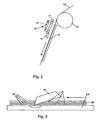
- Fig. 1
- eine Perforationseinrichtung eines Oberbaus für einen Falzapparat;
- Fig. 2
- eine Längstrenneinrichtung des Falzapparats;
- Fig. 3
- die Lage von Stegen mehrerer übereinanderliegender zu zertrennender Materialbahnen beim Einsatz des Oberbaus zur gleichzeitigen Verarbeitung mehrerer Materialbahnen.
- Fig. 1
- a perforation device of a superstructure for a folder;
- Fig. 2
- a longitudinal separator of the folder;
- Fig. 3
- the location of webs of several superimposed material webs to be cut when using the superstructure for the simultaneous processing of multiple webs.
Fig. 1 zeigt eine schematische Ansicht einer Perforationseinrichtung für den
erfindungsgemäßen Oberbau. Die Perforationseinrichtung umfasst eine zwischen zwei
(nicht dargestellten) Seitenplatten drehbar gelagerte Umlenkwalze 01, über die eine
Ausgangsmaterialbahn 02 straffgespannt geführt ist. Zwischen den zwei Seitenplatten ist
femer eine Stange 03 unbeweglich gehalten. An der Stange 03 ist ein Spannklotz 04 mit
Hilfe einer oder mehrerer Schrauben lösbar befestigt. Der Spannklotz 04 ist im gelösten
Zustand um die Stange 03 drehbar und in ihrer axialen Richtung, d.h. senkrecht zur
Ebene der Fig. 1, verschiebbar. Ein Ring 06 ist an der Stange 03 drehbar, aber in seiner
axialen Position durch den Spannklotz 04 festgelegt.Fig. 1 shows a schematic view of a perforation device for the
inventive superstructure. The perforator comprises one between two
(not shown) side plates rotatably mounted
Der Ring 06 trägt an einem Arm 07 ein Gehäuse 08, das in der Fig. 1 teilweise
aufgeschnitten gezeigt ist. In dem Gehäuse 08 ist ein Kreismesser 09 drehbar. Das
Kreismesser 09 ist dort, wo es innerhalb des Gehäuses 08 liegt, gestrichelt dargestellt;
lediglich im unteren, der Umlenkwalze 01 zugewandten Bereich des Gehäuses 08 ragt
das Kreismesser 09 heraus. Die Schneidkante des Kreismessers weist zwei diametral
einander gegenüberliegende Unterbrechungen 11 auf, die jeweils eine Länge von 3 mm
aufweisen, der Gesamtumfang des Kreismessers 09 beträgt ca. 300 mm.The
Die Schneidkante des Kreismessers 09 greift in eine (nicht dargestellte) Schneidnut in der
Umlenkwalze 01 ein, die so als Untermesser zu dem Kreismesser wirkt. Die Tiefe der
Unterbrechungen 11 in der Schneidkante ist größer als die der Schneidnut, so dass selbst
dann, wenn das Kreismesser 09 bis zum Boden der Nut in diese eintaucht, die
Ausgangsmaterialbahn 02 nicht auf ihrer gesamten Länge geschnitten werden kann und
zwischen benachbarten Teilbahnen jeweils in einem Abstand von ca. 150 mm Stege mit
einer den Abmessungen der Unterbrechungen 11 entsprechenden Länge von 3 mm
verbleiben.The cutting edge of the
Ein Hydraulikzylinder 12, dessen Versorgungsleitungen in der Fig. 1 der Übersichtlichkeit
halber nicht gezeigt sind, ist zwischen dem Spannklotz 04 und einem abgewinkelten
Venangerungsabschnitt 13 des Arms 07 gelenkig angeordnet. Durch eine entsprechende
Ansteuerung des Hydraulikzylinders 12 kann der Arm 07 aus seiner in der Fig. 1
gezeigten Stellung, in der das Kreismesser 09 in die Schneidnut eingreift, in eine inaktive
Stellung angehoben werden, in der keine Perforation gebildet wird.A
Eine Perforationseinrichtung kann eine Mehrzahl von Anordnungen aus Arm 07,
Kreismesser 09 und Hydraulikzylinder 12 umfassen, die jeweils an unterschiedlichen
axialen Positionen der Stange 03 angeordnet sind. Durch Verschwenken einzelner dieser
Anordnungen in die inaktive Position kann die gewünschte Zahl von Teilmaterialbahnen
festgelegt werden, in die die Ausgangsmaterialbahn 02 zerlegt werden soll.A perforating device may comprise a plurality of arrangements of
Da nach dem Durchgang durch die Perforationseinrichtung der Fig. 1 die
Tellmaterialbahnen jeweils noch durch Stege 19 verbunden sind, können sie über längere
Strecken weiter gefördert werden, ohne dass die Gefahr einer unkontrollierten seitlichen
Wanderbewegung der Teilbahnen auftritt, die zu einem teilweisen Überlappen der
Teilbahnen bei ihrem Eintritt in den Falzapparat führen könnte.Since after passing through the perforation of Fig. 1, the
Tellmaterialbahnen are still connected by
Fig. 2 zeigt schematisch die Zuführung einer perforierten Ausgangsmaterialbahn 02
entlang einer Wand 14 eines Falztrichters am Eingang eines Falzapparats. Die perforierte
Materialbahn 02 läuft zwischen der Wand 14 und einer Trenneinrichtung 16 durch. Diese
Trenneinrichtung 16 umfasst eine ortsfeste Stange 17, an der Trennklingen 18 jeweils in
einer der Zahl der Kreismesser 09 entsprechenden Anzahl und in entsprechenden,
veränderbaren axialen Positionen entlang der Stange 17 montiert sind. 2 shows schematically the supply of a perforated starting
Jeder Trennklinge 18 ist ein Hydraulikzylinder 21 als Stellglied zugeordnet, mit dem die
Trennklinge 18 aus der in der Fig. 2 gezeigten, inaktiven Position in eine Position
verstellbar ist, in der sie jeweils in eine Perforation der Materialbahn 02 eingreift und mit
der Spitze die Wand 14 berührt oder in einen Schlitz dieser Wand eingreift.Each separating
Fig. 3 zeigt den Fall einer Trennklinge 18, die zum Auseinandertrennen mehrerer, zu
einem Stapel 22 übereinandergelegter, vorperforierter Ausgangsmaterialbahnen 02
eingesetzt wird. Diese Ausgangsmaterialbahnen 02 sind jeweils über getrennte
Zufuhrwege mit jeweils einer eigenen Perforationseinrichtung zu dem Falztrichter geführt,
an dessen Wand 14 die Trennklinge 18 angeordnet ist Diese mehreren
Perforationseinrichtungen haben jeweils Kreismesser mit gleichen Abmessungen, diese
werden allerdings mit solchen Drehwinkeln relativ zueinander betrieben, dass unter
Berücksichtigung der von jeder einzelnen Perforationseinrichtung zu der Trenneinrichtung
16 zurückzulegenden Wege die einzelnen Ausgangsmaterialbahnen 02 an der
Trenneinrichtung 16 mit gegeneinander versetzten Stegen 19 eintreffen. Wie man in Fig.
3 erkennt, durchtrennt die Trennklinge 18 daher zu jeder Zeit höchstens einen Steg 19.
Die von der Trennklinge 18 auf die Materialbahnen 02 ausgeübte Bremskraft ist daher
immer gering und schwankt nur in geringem Umfang, so dass Gleichlaufstörungen der
Materialbahnen oder Reißen vermieden werden, die andernfalls beim gleichzeitigen
Eintreffen einer Mehrzahl von Stegen 19 an der Trennklinge 18 auftreten könnten.
Selbstverständlich könnte die Trenneinrichtung 16 anstelle einer einfachen festen Klinge
18 auch eine mit der Geschwindigkeit der Materialbahnen 02 rotierende Klinge aufweisen,
um Bremsbelastungen der Materialbahnen zu vermeiden. Fig. 3 shows the case of a separating
- 0101
- Umlenkwalzedeflecting
- 0202
- Ausgangs-MaterialbahnOutput web
- 0303
- Stangepole
- 0404
- Spannklotzclamping block
- 0505
- --
- 0606
- Ringring
- 0707
- Armpoor
- 0808
- Gehäusecasing
- 0909
- Kreismessercircular blade
- 1010
- --
- 1111
- Unterbrechunginterruption
- 1212
- Hydraulikzylinderhydraulic cylinders
- 1313
- Verlängerungsabschnittextension section
- 1414
- Wandwall
- 1515
- --
- 1616
- Trenneinrichtungseparator
- 1717
- Stangepole
- 1818
- Trennklingerelease blade
- 1919
- Stegweb
- 2020
- --
- 2121
- Hydraulikzylinderhydraulic cylinders
- 2222
- Stapelstack
Claims (10)
- Top-structure of a folding apparatus having a folding funnel for feeding a plurality of part-webs of material lying next to one another into the folding apparatus, a perforating arrangement for making at least one longitudinal perforation in a starting web of material (02) being arranged upstream of the folding funnel, characterised in that a longitudinal dividing arrangement (16) is arranged in the folding funnel to divide the starting web of material (02) into a plurality of part-webs of material on the folding funnel, along the perforation.
- Top-structure according to claim 1, characterised in that the perforating arrangement is mounted on a direction-changing roller (01).
- Top-structure according to claim 1 or 2, characterised in that the perforating arrangement comprises at least one blade, and in particular a circular blade (09), whose revolving cutting edge has at least one non-cutting interruption (11).
- Top-structure according to claim 3, characterised in that the cutting edge of the circular blade (09) has two diametrically opposed interruptions (11).
- Top-structure according to claim 3 or 4, characterised in that the non-cutting interruption (11) is a notch in the circular blade (09), whose depth is greater than that of a groove, which co-operates with the circular blade, in a bottom blade.
- Top-structure according to one of claims 3 to 5, characterised in that the interruption (11) has a length of 1 to 5 mm.
- Top-structure according to one of claims 3 to 6, characterised in that the ratio of the length of the non-cutting interruption or interruptions (11) to the circumferential length of the circular blade (09) is less than 10% and preferably between 1 and 3%.
- Top-structure according to one of the foregoing claims, characterised in that it comprises a plurality of infeed paths each for feeding one starting web of material (02) to the folding funnel, and in that each infeed path has a perforating arrangement.
- Top-structure according to claim 8, characterised in that the perforating arrangements can be operated with a phasing such that bridges (19) which are left between adjacent part-webs of different starting webs of material (02) after the perforating are staggered relative to one another in the direction of feed at the longitudinal dividing arrangement (16).
- Top-structure according to claim 8 or 9, characterised in that the longitudinal dividing arrangement (16) acts on a stack (22) of webs of material which is formed by the laying on top of one another of a plurality of starting webs of material (02) which are fed in along different infeed paths.
Priority Applications (1)
| Application Number | Priority Date | Filing Date | Title |
|---|---|---|---|
| EP04102587A EP1493703B1 (en) | 2001-02-14 | 2001-11-27 | Method for feeding partial webs of material |
Applications Claiming Priority (3)
| Application Number | Priority Date | Filing Date | Title |
|---|---|---|---|
| DE10106670 | 2001-02-14 | ||
| DE10106670A DE10106670B4 (en) | 2001-02-14 | 2001-02-14 | Superstructure for a folder and method for feeding a plurality of starting material webs |
| PCT/DE2001/004450 WO2002064474A1 (en) | 2001-02-14 | 2001-11-27 | Folding machine superstructure and method for feeding partial webs of material |
Related Child Applications (1)
| Application Number | Title | Priority Date | Filing Date |
|---|---|---|---|
| EP04102587A Division EP1493703B1 (en) | 2001-02-14 | 2001-11-27 | Method for feeding partial webs of material |
Publications (2)
| Publication Number | Publication Date |
|---|---|
| EP1360136A1 EP1360136A1 (en) | 2003-11-12 |
| EP1360136B1 true EP1360136B1 (en) | 2005-04-13 |
Family
ID=7673903
Family Applications (2)
| Application Number | Title | Priority Date | Filing Date |
|---|---|---|---|
| EP01273712A Expired - Lifetime EP1360136B1 (en) | 2001-02-14 | 2001-11-27 | Folding machine superstructure |
| EP04102587A Expired - Lifetime EP1493703B1 (en) | 2001-02-14 | 2001-11-27 | Method for feeding partial webs of material |
Family Applications After (1)
| Application Number | Title | Priority Date | Filing Date |
|---|---|---|---|
| EP04102587A Expired - Lifetime EP1493703B1 (en) | 2001-02-14 | 2001-11-27 | Method for feeding partial webs of material |
Country Status (5)
| Country | Link |
|---|---|
| EP (2) | EP1360136B1 (en) |
| AT (2) | ATE293082T1 (en) |
| DE (3) | DE10106670B4 (en) |
| ES (2) | ES2246052T3 (en) |
| WO (1) | WO2002064474A1 (en) |
Families Citing this family (1)
| Publication number | Priority date | Publication date | Assignee | Title |
|---|---|---|---|---|
| DE10332671B4 (en) * | 2003-07-18 | 2007-12-20 | Koenig & Bauer Aktiengesellschaft | Device for cutting cut sheets in the delivery of a printing machine |
Family Cites Families (9)
| Publication number | Priority date | Publication date | Assignee | Title |
|---|---|---|---|---|
| US2077403A (en) * | 1930-10-09 | 1937-04-20 | Eiseman Maurice | Printing press for newspaper work |
| CA1032193A (en) * | 1974-10-11 | 1978-05-30 | Marlin A. Schueler | Separator for handling multi-folded paper |
| AU3327478A (en) * | 1977-03-02 | 1979-08-23 | Rockwell International Corp | Web folding and slitting apparatus |
| JPS5738265A (en) * | 1980-08-18 | 1982-03-02 | Toshiba Mach Co Ltd | Fold introducing part of rotary press machine |
| JP2675565B2 (en) * | 1988-01-11 | 1997-11-12 | 三菱重工業株式会社 | Pinless folding method and device |
| US5230501A (en) * | 1992-01-16 | 1993-07-27 | Quad/Tech, Inc. | Apparatus and method for integrating an insert assembly on a printing press |
| DE4319806A1 (en) * | 1993-06-15 | 1995-01-05 | Koenig & Bauer Ag | Paper strand inlet in a longitudinal folding funnel |
| DE59605687D1 (en) * | 1995-11-08 | 2000-09-07 | Koenig & Bauer Ag | METHOD AND DEVICE FOR PRODUCING MULTIPLE-PAGE NEWSPAPER PRODUCTS WITH TABLOID PART |
| US6394330B1 (en) * | 1998-08-13 | 2002-05-28 | 3M Innovative Properties Company | Method for slitting and processing a web into plural use supply forms |
-
2001
- 2001-02-14 DE DE10106670A patent/DE10106670B4/en not_active Expired - Fee Related
- 2001-11-27 AT AT01273712T patent/ATE293082T1/en not_active IP Right Cessation
- 2001-11-27 EP EP01273712A patent/EP1360136B1/en not_active Expired - Lifetime
- 2001-11-27 AT AT04102587T patent/ATE302732T1/en not_active IP Right Cessation
- 2001-11-27 DE DE50107232T patent/DE50107232D1/en not_active Expired - Fee Related
- 2001-11-27 ES ES04102587T patent/ES2246052T3/en not_active Expired - Lifetime
- 2001-11-27 WO PCT/DE2001/004450 patent/WO2002064474A1/en not_active Application Discontinuation
- 2001-11-27 EP EP04102587A patent/EP1493703B1/en not_active Expired - Lifetime
- 2001-11-27 ES ES01273712T patent/ES2238388T3/en not_active Expired - Lifetime
- 2001-11-27 DE DE50105923T patent/DE50105923D1/en not_active Expired - Fee Related
Also Published As
| Publication number | Publication date |
|---|---|
| EP1493703B1 (en) | 2005-08-24 |
| ES2238388T3 (en) | 2005-09-01 |
| ATE293082T1 (en) | 2005-04-15 |
| ES2246052T3 (en) | 2006-02-01 |
| DE50107232D1 (en) | 2005-09-29 |
| DE10106670B4 (en) | 2004-01-29 |
| WO2002064474A1 (en) | 2002-08-22 |
| DE10106670A1 (en) | 2002-08-29 |
| EP1360136A1 (en) | 2003-11-12 |
| EP1493703A1 (en) | 2005-01-05 |
| DE50105923D1 (en) | 2005-05-19 |
| ATE302732T1 (en) | 2005-09-15 |
Similar Documents
| Publication | Publication Date | Title |
|---|---|---|
| EP1072551B1 (en) | Folding method and folding apparatus arrangement in a rotary newspaper printing press | |
| EP0986454B1 (en) | Method and device for cross-perforating a moving paper strip | |
| DE102008033776B4 (en) | Corrugating machine | |
| EP0859733B1 (en) | Process and device for producing multi-layered newspaper products with a tabloid section | |
| EP1105333B1 (en) | Method and device for perforating material bands | |
| DE10116346B4 (en) | folding | |
| EP1010503B1 (en) | Cutting device including a first and a second row of cutting blades which can be relatively moved along parallel directions | |
| DE102004002210A1 (en) | Method and device for synchronizing cutting at the end of the job for an immersion slot job change in a corrugated cardboard machine | |
| DE102004046127A1 (en) | Corrugated board plant and process for the production of corrugated sheets | |
| EP1360136B1 (en) | Folding machine superstructure | |
| EP2123585B1 (en) | Method and device for processing a moved, printed sheet of material | |
| EP1970339B1 (en) | Folding unit of a roller printing press | |
| DE2722233B2 (en) | Machine for longitudinal cutting and longitudinal creasing of material webs, in particular made of corrugated cardboard | |
| DE10209214B4 (en) | cutter | |
| DE10209190B4 (en) | Cutting device for cross cutting at least one material web | |
| DE10209213B4 (en) | transport device | |
| EP2388114B1 (en) | Device for laterally transverse or cutting mobile sheets of material | |
| DE102005033572B4 (en) | Folder of a printing machine | |
| EP1620343B1 (en) | Rotary folder comprising a cutting device for cross-cutting at least one web | |
| EP1652639A1 (en) | Method for changing the format in a corrugated board manufacturing plant | |
| EP3398891B1 (en) | Device for producing collections of sheet-shaped printed products, and corresponding folding apparatus for folding collections of sheet-shaped printed products | |
| DE3937024A1 (en) | DEVICE FOR PRODUCING INSERTS FOR SHIPPING SHELLS | |
| DE202022106592U1 (en) | Printing machine for the production of tabloid products | |
| DE102014222387B4 (en) | Process for the production of a printed product as well as a printed product | |
| EP1077192B1 (en) | Method of winding a running material web |
Legal Events
| Date | Code | Title | Description |
|---|---|---|---|
| PUAI | Public reference made under article 153(3) epc to a published international application that has entered the european phase |
Free format text: ORIGINAL CODE: 0009012 |
|
| 17P | Request for examination filed |
Effective date: 20030703 |
|
| AK | Designated contracting states |
Kind code of ref document: A1 Designated state(s): AT BE CH CY DE DK ES FI FR GB GR IE IT LI LU MC NL PT SE TR |
|
| AX | Request for extension of the european patent |
Extension state: AL LT LV MK RO SI |
|
| 17Q | First examination report despatched |
Effective date: 20040423 |
|
| RTI1 | Title (correction) |
Free format text: FOLDING MACHINE SUPERSTRUCTURE |
|
| GRAP | Despatch of communication of intention to grant a patent |
Free format text: ORIGINAL CODE: EPIDOSNIGR1 |
|
| GRAS | Grant fee paid |
Free format text: ORIGINAL CODE: EPIDOSNIGR3 |
|
| GRAA | (expected) grant |
Free format text: ORIGINAL CODE: 0009210 |
|
| AK | Designated contracting states |
Kind code of ref document: B1 Designated state(s): AT BE CH CY DE DK ES FI FR GB GR IE IT LI LU MC NL PT SE TR |
|
| PG25 | Lapsed in a contracting state [announced via postgrant information from national office to epo] |
Ref country code: IT Free format text: LAPSE BECAUSE OF FAILURE TO SUBMIT A TRANSLATION OF THE DESCRIPTION OR TO PAY THE FEE WITHIN THE PRESCRIBED TIME-LIMIT;WARNING: LAPSES OF ITALIAN PATENTS WITH EFFECTIVE DATE BEFORE 2007 MAY HAVE OCCURRED AT ANY TIME BEFORE 2007. THE CORRECT EFFECTIVE DATE MAY BE DIFFERENT FROM THE ONE RECORDED. Effective date: 20050413 Ref country code: IE Free format text: LAPSE BECAUSE OF FAILURE TO SUBMIT A TRANSLATION OF THE DESCRIPTION OR TO PAY THE FEE WITHIN THE PRESCRIBED TIME-LIMIT Effective date: 20050413 Ref country code: NL Free format text: LAPSE BECAUSE OF FAILURE TO SUBMIT A TRANSLATION OF THE DESCRIPTION OR TO PAY THE FEE WITHIN THE PRESCRIBED TIME-LIMIT Effective date: 20050413 Ref country code: FI Free format text: LAPSE BECAUSE OF FAILURE TO SUBMIT A TRANSLATION OF THE DESCRIPTION OR TO PAY THE FEE WITHIN THE PRESCRIBED TIME-LIMIT Effective date: 20050413 Ref country code: TR Free format text: LAPSE BECAUSE OF FAILURE TO SUBMIT A TRANSLATION OF THE DESCRIPTION OR TO PAY THE FEE WITHIN THE PRESCRIBED TIME-LIMIT Effective date: 20050413 |
|
| REG | Reference to a national code |
Ref country code: GB Ref legal event code: FG4D Free format text: NOT ENGLISH |
|
| REG | Reference to a national code |
Ref country code: CH Ref legal event code: EP |
|
| REG | Reference to a national code |
Ref country code: IE Ref legal event code: FG4D Free format text: LANGUAGE OF EP DOCUMENT: GERMAN |
|
| REF | Corresponds to: |
Ref document number: 50105923 Country of ref document: DE Date of ref document: 20050519 Kind code of ref document: P |
|
| PG25 | Lapsed in a contracting state [announced via postgrant information from national office to epo] |
Ref country code: SE Free format text: LAPSE BECAUSE OF FAILURE TO SUBMIT A TRANSLATION OF THE DESCRIPTION OR TO PAY THE FEE WITHIN THE PRESCRIBED TIME-LIMIT Effective date: 20050713 Ref country code: DK Free format text: LAPSE BECAUSE OF FAILURE TO SUBMIT A TRANSLATION OF THE DESCRIPTION OR TO PAY THE FEE WITHIN THE PRESCRIBED TIME-LIMIT Effective date: 20050713 Ref country code: GR Free format text: LAPSE BECAUSE OF FAILURE TO SUBMIT A TRANSLATION OF THE DESCRIPTION OR TO PAY THE FEE WITHIN THE PRESCRIBED TIME-LIMIT Effective date: 20050713 |
|
| GBT | Gb: translation of ep patent filed (gb section 77(6)(a)/1977) |
Effective date: 20050802 |
|
| REG | Reference to a national code |
Ref country code: ES Ref legal event code: FG2A Ref document number: 2238388 Country of ref document: ES Kind code of ref document: T3 |
|
| PG25 | Lapsed in a contracting state [announced via postgrant information from national office to epo] |
Ref country code: PT Free format text: LAPSE BECAUSE OF FAILURE TO SUBMIT A TRANSLATION OF THE DESCRIPTION OR TO PAY THE FEE WITHIN THE PRESCRIBED TIME-LIMIT Effective date: 20050913 |
|
| NLV1 | Nl: lapsed or annulled due to failure to fulfill the requirements of art. 29p and 29m of the patents act | ||
| PG25 | Lapsed in a contracting state [announced via postgrant information from national office to epo] |
Ref country code: AT Free format text: LAPSE BECAUSE OF NON-PAYMENT OF DUE FEES Effective date: 20051127 Ref country code: CY Free format text: LAPSE BECAUSE OF FAILURE TO SUBMIT A TRANSLATION OF THE DESCRIPTION OR TO PAY THE FEE WITHIN THE PRESCRIBED TIME-LIMIT Effective date: 20051127 |
|
| PG25 | Lapsed in a contracting state [announced via postgrant information from national office to epo] |
Ref country code: BE Free format text: LAPSE BECAUSE OF NON-PAYMENT OF DUE FEES Effective date: 20051130 Ref country code: LU Free format text: LAPSE BECAUSE OF NON-PAYMENT OF DUE FEES Effective date: 20051130 Ref country code: MC Free format text: LAPSE BECAUSE OF NON-PAYMENT OF DUE FEES Effective date: 20051130 |
|
| REG | Reference to a national code |
Ref country code: IE Ref legal event code: FD4D |
|
| ET | Fr: translation filed | ||
| PLBE | No opposition filed within time limit |
Free format text: ORIGINAL CODE: 0009261 |
|
| STAA | Information on the status of an ep patent application or granted ep patent |
Free format text: STATUS: NO OPPOSITION FILED WITHIN TIME LIMIT |
|
| 26N | No opposition filed |
Effective date: 20060116 |
|
| BERE | Be: lapsed |
Owner name: KOENIG & BAUER A.G. Effective date: 20051130 |
|
| PGFP | Annual fee paid to national office [announced via postgrant information from national office to epo] |
Ref country code: CH Payment date: 20081124 Year of fee payment: 8 |
|
| PGFP | Annual fee paid to national office [announced via postgrant information from national office to epo] |
Ref country code: ES Payment date: 20081113 Year of fee payment: 8 |
|
| PGFP | Annual fee paid to national office [announced via postgrant information from national office to epo] |
Ref country code: FR Payment date: 20081117 Year of fee payment: 8 |
|
| PGFP | Annual fee paid to national office [announced via postgrant information from national office to epo] |
Ref country code: DE Payment date: 20081212 Year of fee payment: 8 |
|
| PGFP | Annual fee paid to national office [announced via postgrant information from national office to epo] |
Ref country code: GB Payment date: 20081119 Year of fee payment: 8 |
|
| REG | Reference to a national code |
Ref country code: CH Ref legal event code: PL |
|
| GBPC | Gb: european patent ceased through non-payment of renewal fee |
Effective date: 20091127 |
|
| REG | Reference to a national code |
Ref country code: FR Ref legal event code: ST Effective date: 20100730 |
|
| PG25 | Lapsed in a contracting state [announced via postgrant information from national office to epo] |
Ref country code: LI Free format text: LAPSE BECAUSE OF NON-PAYMENT OF DUE FEES Effective date: 20091130 Ref country code: CH Free format text: LAPSE BECAUSE OF NON-PAYMENT OF DUE FEES Effective date: 20091130 Ref country code: FR Free format text: LAPSE BECAUSE OF NON-PAYMENT OF DUE FEES Effective date: 20091130 |
|
| PG25 | Lapsed in a contracting state [announced via postgrant information from national office to epo] |
Ref country code: DE Free format text: LAPSE BECAUSE OF NON-PAYMENT OF DUE FEES Effective date: 20100601 |
|
| PG25 | Lapsed in a contracting state [announced via postgrant information from national office to epo] |
Ref country code: GB Free format text: LAPSE BECAUSE OF NON-PAYMENT OF DUE FEES Effective date: 20091127 |
|
| REG | Reference to a national code |
Ref country code: ES Ref legal event code: FD2A Effective date: 20110330 |
|
| PG25 | Lapsed in a contracting state [announced via postgrant information from national office to epo] |
Ref country code: ES Free format text: LAPSE BECAUSE OF NON-PAYMENT OF DUE FEES Effective date: 20110317 |
|
| PG25 | Lapsed in a contracting state [announced via postgrant information from national office to epo] |
Ref country code: ES Free format text: LAPSE BECAUSE OF NON-PAYMENT OF DUE FEES Effective date: 20091128 |