EP1359306A2 - Kraftstoffeinspritzeinrichtung für eine Brennkraftmaschine - Google Patents
Kraftstoffeinspritzeinrichtung für eine Brennkraftmaschine Download PDFInfo
- Publication number
- EP1359306A2 EP1359306A2 EP03004640A EP03004640A EP1359306A2 EP 1359306 A2 EP1359306 A2 EP 1359306A2 EP 03004640 A EP03004640 A EP 03004640A EP 03004640 A EP03004640 A EP 03004640A EP 1359306 A2 EP1359306 A2 EP 1359306A2
- Authority
- EP
- European Patent Office
- Prior art keywords
- pressure
- fuel
- low
- pressure accumulator
- control valve
- Prior art date
- Legal status (The legal status is an assumption and is not a legal conclusion. Google has not performed a legal analysis and makes no representation as to the accuracy of the status listed.)
- Granted
Links
Images

Classifications
-
- F—MECHANICAL ENGINEERING; LIGHTING; HEATING; WEAPONS; BLASTING
- F02—COMBUSTION ENGINES; HOT-GAS OR COMBUSTION-PRODUCT ENGINE PLANTS
- F02M—SUPPLYING COMBUSTION ENGINES IN GENERAL WITH COMBUSTIBLE MIXTURES OR CONSTITUENTS THEREOF
- F02M63/00—Other fuel-injection apparatus having pertinent characteristics not provided for in groups F02M39/00 - F02M57/00 or F02M67/00; Details, component parts, or accessories of fuel-injection apparatus, not provided for in, or of interest apart from, the apparatus of groups F02M39/00 - F02M61/00 or F02M67/00; Combination of fuel pump with other devices, e.g. lubricating oil pump
- F02M63/02—Fuel-injection apparatus having several injectors fed by a common pumping element, or having several pumping elements feeding a common injector; Fuel-injection apparatus having provisions for cutting-out pumps, pumping elements, or injectors; Fuel-injection apparatus having provisions for variably interconnecting pumping elements and injectors alternatively
- F02M63/0225—Fuel-injection apparatus having a common rail feeding several injectors ; Means for varying pressure in common rails; Pumps feeding common rails
- F02M63/0275—Arrangement of common rails
- F02M63/0285—Arrangement of common rails having more than one common rail
- F02M63/029—Arrangement of common rails having more than one common rail per cylinder bank, e.g. storing different fuels or fuels at different pressure levels per cylinder bank
-
- F—MECHANICAL ENGINEERING; LIGHTING; HEATING; WEAPONS; BLASTING
- F02—COMBUSTION ENGINES; HOT-GAS OR COMBUSTION-PRODUCT ENGINE PLANTS
- F02D—CONTROLLING COMBUSTION ENGINES
- F02D41/00—Electrical control of supply of combustible mixture or its constituents
- F02D41/30—Controlling fuel injection
- F02D41/38—Controlling fuel injection of the high pressure type
- F02D41/3809—Common rail control systems
-
- F—MECHANICAL ENGINEERING; LIGHTING; HEATING; WEAPONS; BLASTING
- F02—COMBUSTION ENGINES; HOT-GAS OR COMBUSTION-PRODUCT ENGINE PLANTS
- F02M—SUPPLYING COMBUSTION ENGINES IN GENERAL WITH COMBUSTIBLE MIXTURES OR CONSTITUENTS THEREOF
- F02M47/00—Fuel-injection apparatus operated cyclically with fuel-injection valves actuated by fluid pressure
- F02M47/02—Fuel-injection apparatus operated cyclically with fuel-injection valves actuated by fluid pressure of accumulator-injector type, i.e. having fuel pressure of accumulator tending to open, and fuel pressure in other chamber tending to close, injection valves and having means for periodically releasing that closing pressure
- F02M47/027—Electrically actuated valves draining the chamber to release the closing pressure
-
- F—MECHANICAL ENGINEERING; LIGHTING; HEATING; WEAPONS; BLASTING
- F02—COMBUSTION ENGINES; HOT-GAS OR COMBUSTION-PRODUCT ENGINE PLANTS
- F02M—SUPPLYING COMBUSTION ENGINES IN GENERAL WITH COMBUSTIBLE MIXTURES OR CONSTITUENTS THEREOF
- F02M63/00—Other fuel-injection apparatus having pertinent characteristics not provided for in groups F02M39/00 - F02M57/00 or F02M67/00; Details, component parts, or accessories of fuel-injection apparatus, not provided for in, or of interest apart from, the apparatus of groups F02M39/00 - F02M61/00 or F02M67/00; Combination of fuel pump with other devices, e.g. lubricating oil pump
- F02M63/02—Fuel-injection apparatus having several injectors fed by a common pumping element, or having several pumping elements feeding a common injector; Fuel-injection apparatus having provisions for cutting-out pumps, pumping elements, or injectors; Fuel-injection apparatus having provisions for variably interconnecting pumping elements and injectors alternatively
- F02M63/0225—Fuel-injection apparatus having a common rail feeding several injectors ; Means for varying pressure in common rails; Pumps feeding common rails
- F02M63/023—Means for varying pressure in common rails
- F02M63/0235—Means for varying pressure in common rails by bleeding fuel pressure
- F02M63/025—Means for varying pressure in common rails by bleeding fuel pressure from the common rail
-
- F—MECHANICAL ENGINEERING; LIGHTING; HEATING; WEAPONS; BLASTING
- F02—COMBUSTION ENGINES; HOT-GAS OR COMBUSTION-PRODUCT ENGINE PLANTS
- F02M—SUPPLYING COMBUSTION ENGINES IN GENERAL WITH COMBUSTIBLE MIXTURES OR CONSTITUENTS THEREOF
- F02M69/00—Low-pressure fuel-injection apparatus ; Apparatus with both continuous and intermittent injection; Apparatus injecting different types of fuel
- F02M69/46—Details, component parts or accessories not provided for in, or of interest apart from, the apparatus covered by groups F02M69/02 - F02M69/44
- F02M69/54—Arrangement of fuel pressure regulators
-
- F—MECHANICAL ENGINEERING; LIGHTING; HEATING; WEAPONS; BLASTING
- F02—COMBUSTION ENGINES; HOT-GAS OR COMBUSTION-PRODUCT ENGINE PLANTS
- F02D—CONTROLLING COMBUSTION ENGINES
- F02D2200/00—Input parameters for engine control
- F02D2200/02—Input parameters for engine control the parameters being related to the engine
- F02D2200/06—Fuel or fuel supply system parameters
- F02D2200/0606—Fuel temperature
-
- F—MECHANICAL ENGINEERING; LIGHTING; HEATING; WEAPONS; BLASTING
- F02—COMBUSTION ENGINES; HOT-GAS OR COMBUSTION-PRODUCT ENGINE PLANTS
- F02D—CONTROLLING COMBUSTION ENGINES
- F02D41/00—Electrical control of supply of combustible mixture or its constituents
- F02D41/02—Circuit arrangements for generating control signals
- F02D41/04—Introducing corrections for particular operating conditions
- F02D41/06—Introducing corrections for particular operating conditions for engine starting or warming up
- F02D41/062—Introducing corrections for particular operating conditions for engine starting or warming up for starting
-
- F—MECHANICAL ENGINEERING; LIGHTING; HEATING; WEAPONS; BLASTING
- F02—COMBUSTION ENGINES; HOT-GAS OR COMBUSTION-PRODUCT ENGINE PLANTS
- F02D—CONTROLLING COMBUSTION ENGINES
- F02D41/00—Electrical control of supply of combustible mixture or its constituents
- F02D41/20—Output circuits, e.g. for controlling currents in command coils
- F02D41/2096—Output circuits, e.g. for controlling currents in command coils for controlling piezoelectric injectors
-
- F—MECHANICAL ENGINEERING; LIGHTING; HEATING; WEAPONS; BLASTING
- F02—COMBUSTION ENGINES; HOT-GAS OR COMBUSTION-PRODUCT ENGINE PLANTS
- F02M—SUPPLYING COMBUSTION ENGINES IN GENERAL WITH COMBUSTIBLE MIXTURES OR CONSTITUENTS THEREOF
- F02M2200/00—Details of fuel-injection apparatus, not otherwise provided for
- F02M2200/70—Linkage between actuator and actuated element, e.g. between piezoelectric actuator and needle valve or pump plunger
- F02M2200/703—Linkage between actuator and actuated element, e.g. between piezoelectric actuator and needle valve or pump plunger hydraulic
- F02M2200/705—Linkage between actuator and actuated element, e.g. between piezoelectric actuator and needle valve or pump plunger hydraulic with means for filling or emptying hydraulic chamber, e.g. for compensating clearance or thermal expansion
Definitions
- the invention is based on one Fuel injection device for an internal combustion engine according to the preamble of claim 1.
- Such a fuel injector is due to the DE 199 41 770 A1 known.
- This Fuel injector has a high pressure pump on, through the fuel under high pressure in at least a high-pressure accumulator is promoted.
- the High-pressure accumulators are on cylinders of the internal combustion engine arranged injectors connected.
- the injectors are included a common return line connected to one Low pressure accumulator forms. In the low pressure accumulator a minimum pressure to be maintained to the To ensure that the injectors are functional, especially if this is a control valve with a piezoelectric actuator and a hydraulic Have translation facility.
- the fuel injection device with the Features according to claim 1 has the advantage that a minimum pressure in the Low pressure accumulator can be maintained. Moreover can be targeted by diverting fuel from the High pressure accumulator by means of the pressure control valve Low pressure accumulator can be filled with fuel, whereby no additional feed pump is required. The one from the High-pressure accumulator fuel is warmed up so that the injectors quickly reach their operating temperature brought and their operation is stabilized.
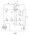
- FIG. 1 shows a Fuel injection device for an internal combustion engine in a simplified schematic representation and Figure 2 a Injector of the fuel injector in an enlarged view Presentation.
- FIG 1 is a fuel injection device for a Internal combustion engine of a motor vehicle shown.
- the Internal combustion engine is preferably a self-igniting Internal combustion engine.
- the fuel injector has a high pressure pump 10 through which fuel is taken High pressure promoted in at least one high pressure accumulator 12 becomes.
- the high pressure pump 10 is mechanically by the Internal combustion engine driven and this has one or several pump elements by a drive in one Stroke movement are driven.
- the suction side of the High pressure pump 10 is fuel from a Fuel reservoir 14 by means of a feed pump 16 fed.
- the feed pump 16 can by the high pressure pump 10 or together with the high pressure pump 10 through the Internal combustion engine are driven.
- the Feed pump 16 also has its own drive, for example have an electric motor drive.
- injectors 20 With the high pressure accumulator 12 are on the cylinders Internal combustion engine arranged injectors 20 connected.
- injectors 20 each have Fuel injection valve 22 and a control valve 24.
- the control valve 24 has a piezoelectric actuator 26 on with an electronic control device 28 is connected and through this with an electrical Voltage is controlled.
- the piezoelectric actuator 26 changes depending on the voltage with which it is controlled , its length and thereby causes a hydraulic Translation device 30 a pressure change in one Actuator pressure chamber 32, through which a control valve member 34 Location changes.
- the fuel injection valve 22 has a Injection valve member 36, which by the im High pressure accumulator 12 prevailing pressure in one Opening direction is applied and that by the in one Control pressure chamber 38 prevailing pressure and possibly a closing spring 40 is acted upon in a closing direction is.
- the injection valve member 36 is at least one Injection opening 42 controlled.
- the control pressure chamber 38 is connected to the high pressure accumulator 12 and has one the control valve member 34 controlled connection to one Relief area on than the at least indirectly the Fuel tank 14 can serve. If the actuator 26 is not controlled and is therefore dead Pressure in the actuator pressure chamber 32 low, so that Control valve member 34 connects the control pressure chamber 38 to the relief area is interrupted.
- control pressure room 38 there is therefore high pressure as in the high-pressure accumulator 12 and the injector member 36 is closed in its Position held so that no fuel injection he follows. If the actuator 26 is controlled by the control device 28 is supplied with an electrical voltage, so increases the pressure in the actuator pressure chamber 32, so that the Control valve member 34 connects the control pressure chamber 38 releases to the relief area. It can from the Control pressure chamber 38 drain fuel so that the pressure decreases and the injection valve member 36 in Opening direction moves, so that fuel injection he follows.
- the hydraulic translation devices 30 of the Injectors 20 have a common low-pressure accumulator 50 connected.
- a Maintaining valve 52 maintain a predetermined pressure, for example between about 5 and 20 bar. If the specified pressure is exceeded, this opens Pressure holding valve 52 and lets fuel out of the Low-pressure accumulator 50 flow away, for example at least indirectly in the fuel tank 14 as Relief area. It can be provided that the at open control valve 24 by means of control valve member 34 de-fueled from the control pressure chamber 38 into the Low pressure accumulator 50 is directed as a relief area.
- each Transmission devices 30 non-return valve 54 arranged through which a filling of the Translation device 30 from the low pressure accumulator 50 is possible, but no fuel from the Translation device 30 in the low pressure accumulator 50 can drain off.
- the low pressure accumulator 50 ensured that the translation devices 30 with Are filled with fuel and thus the injectors 20 are functional.
- the fuel injector also has Pressure control valve 60, by means of which the pressure in High pressure accumulator 12 can be regulated.
- Pressure control valve 60 can fuel from the High-pressure accumulator 12 are shut down, reducing the pressure is reduced in the high pressure accumulator 12.
- the Pressure control valve 60 can be an electrically operated valve be formed, for example as a 2/2-way valve, the between a closed position in which no Fuel can flow out of the high pressure accumulator 12, and an open position in which fuel from the High-pressure accumulator 12 can flow, is switchable.
- the Pressure control valve 60 is controlled by control device 28 controlled by a by means of the pressure control valve 60 variable pressure can be set in the high pressure accumulator 12 can.
- the pressure control valve 60 has a cut-off connection 62 to a low pressure area, which the from the High-pressure accumulator 12 fuel is supplied. According to the invention it is provided that the control connection 62 of the pressure control valve 60 with the low pressure accumulator 50 is connectable as a low pressure area.
- a switching valve 64 is arranged through which the Discharge connection 62 optionally with the low pressure accumulator 50 or with a return 66 in the Fuel reservoir 14 as a relief area is connectable.
- the switching valve 64 can for example are switched depending on the temperature, such that at under a limit temperature lying fuel temperature the Discharge connection 62 with the low pressure accumulator 50 is connected and if it is above the limit temperature Fuel temperature control connection 62 with the Return 66 to the fuel reservoir 14 is connected.
- the changeover valve 64 can be in with the fuel in Have contact standing switching element 68, which depends from the fuel temperature changes shape and thereby the switching causes.
- the switching element 68 can consist of bimetal, for example, due to the different expansion coefficients of two different metals when the temperature changes Shape change results.
Landscapes
- Engineering & Computer Science (AREA)
- Chemical & Material Sciences (AREA)
- Combustion & Propulsion (AREA)
- Mechanical Engineering (AREA)
- General Engineering & Computer Science (AREA)
- Physics & Mathematics (AREA)
- Fluid Mechanics (AREA)
- Fuel-Injection Apparatus (AREA)
Abstract
Description
Claims (6)
- Kraftstoffeinspritzeinrichtung für eine Brennkraftmaschine mit einer Hochdruckpumpe (10), durch die Kraftstoff unter Hochdruck in wenigstens einen Hochdruckspeicher (12) gefördert wird, mit dem an Zylindern der Brennkraftmaschine angeordnete Injektoren (20) verbunden sind, wobei die Injektoren (20) mit einem gemeinsamen Niederdruckspeicher (50) verbunden sind, dadurch gekennzeichnet, daß im Niederdruckspeicher (50) durch ein Druckhalteventil (52) ein vorgegebener Niederdruck aufrechterhalten wird, daß ein Druckregelventil (60) vorgesehen ist, mittels dem durch Absteuern von Kraftstoff aus dem wenigstens einen Hochdruckspeicher (12) über eine Absteuerverbindung (62) in einen Niederdruckbereich der Druck im Hochdruckspeicher (12) regelbar ist und daß die Absteuerverbindung (62) des Druckregelventils (60) mit dem Niederdruckspeicher (50) verbindbar ist.
- Kraftstoffeinspritzeinrichtung nach Anspruch 1, dadurch gekennzeichnet, daß ein Umschaltventil (64) vorgesehen ist, durch das die Absteuerverbindung (62) des Druckregelventils (60) wahlweise mit dem Niederdruckspeicher (50) oder mit einem Entlastungsbereich (66,14) verbindbar ist.
- Kraftstoffeinspritzeinrichtung nach Anspruch 2, dadurch gekennzeichnet, daß das Umschaltventil (64) abhängig von der Temperatur des Kraftstoffs derart geschaltet wird, daß bei geringer Kraftstofftemperatur die Absteuerverbindung (62) des Druckregelventils (60) mit dem Niederdruckspeicher (50) verbunden ist und bei hoher Kraftstofftemperatur die Absteuerverbindung (62) des Druckregelventils (60) mit dem Entlastungsbereich (66,14) verbunden ist.
- Kraftstoffeinspritzeinrichtung nach Anspruch 3, dadurch gekennzeichnet, daß das Umschaltventil (64) ein mit dem Kraftstoff in Kontakt stehendes Schaltelement (68) aufweist, das temperaturabhängig seine Form ändert und dabei die Umschaltung bewirkt.
- Kraftstoffeinspritzeinrichtung nach einem der vorstehenden Ansprüche, dadurch gekennzeichnet, daß das Druckregelventil (60) beim Starten der Brennkraftmaschine derart angesteuert wird, daß dieses Kraftstoff aus dem Hochdruckspeicher (12) absteuert und die Absteuerverbindung (62) des Druckregelventils (60) mit dem Niederdruckspeicher (50) verbunden ist.
- Kraftstoffeinspritzeinrichtung nach einem der vorstehenden Ansprüche, dadurch gekennzeichnet, daß die Injektoren (20) jeweils ein Kraftstoffeinspritzventil (22) und ein dieses steuerndes Steuerventil (24) aufweisen, daß das Steuerventil (24) einen piezoelektrischen Aktor (26) und eine diesem zugeordnete hydraulische Übersetzungseinrichtung (30) aufweist und daß die hydraulische Übersetzungseinrichtung (30) mit dem Niederdruckspeicher (50) verbunden ist und aus diesem befüllt wird.
Applications Claiming Priority (2)
| Application Number | Priority Date | Filing Date | Title |
|---|---|---|---|
| DE10218024A DE10218024A1 (de) | 2002-04-23 | 2002-04-23 | Kraftstoffeinspritzeinrichtung für eine Brennkraftmaschine |
| DE10218024 | 2002-04-23 |
Publications (3)
| Publication Number | Publication Date |
|---|---|
| EP1359306A2 true EP1359306A2 (de) | 2003-11-05 |
| EP1359306A3 EP1359306A3 (de) | 2005-06-15 |
| EP1359306B1 EP1359306B1 (de) | 2008-02-06 |
Family
ID=28798699
Family Applications (1)
| Application Number | Title | Priority Date | Filing Date |
|---|---|---|---|
| EP03004640A Expired - Lifetime EP1359306B1 (de) | 2002-04-23 | 2003-03-03 | Kraftstoffeinspritzeinrichtung für eine Brennkraftmaschine |
Country Status (4)
| Country | Link |
|---|---|
| US (1) | US6823846B2 (de) |
| EP (1) | EP1359306B1 (de) |
| JP (1) | JP4319854B2 (de) |
| DE (2) | DE10218024A1 (de) |
Cited By (4)
| Publication number | Priority date | Publication date | Assignee | Title |
|---|---|---|---|---|
| WO2005010351A1 (de) * | 2003-07-17 | 2005-02-03 | Robert Bosch Gmbh | Kraftstoffeinspritzsystem für verbrennungskraftmaschinen |
| WO2007025803A1 (de) * | 2005-08-30 | 2007-03-08 | Robert Bosch Gmbh | Kraftstoffeinspritzsystem mit verringerter schadstoffemission |
| US7520267B2 (en) | 2005-10-12 | 2009-04-21 | Denso Corporation | Fuel injection apparatus having fuel supplier for displacement amplifying chamber |
| CN105240176A (zh) * | 2015-11-13 | 2016-01-13 | 广西玉柴机器股份有限公司 | 压力可调式燃油分配器 |
Families Citing this family (14)
| Publication number | Priority date | Publication date | Assignee | Title |
|---|---|---|---|---|
| DE10360334A1 (de) * | 2003-12-20 | 2005-07-14 | Robert Bosch Gmbh | Kraftstoffrücklaufsystem mit Drossel |
| DE102004013248A1 (de) * | 2004-03-18 | 2005-10-06 | Robert Bosch Gmbh | Kraftstoffeinspritzeinrichtung für eine Brennkraftmaschine |
| JP4082392B2 (ja) * | 2004-06-30 | 2008-04-30 | トヨタ自動車株式会社 | 内燃機関の燃料供給装置 |
| JP2007285235A (ja) * | 2006-04-18 | 2007-11-01 | Honda Motor Co Ltd | ディーゼルエンジンの燃料供給装置 |
| DE102006023470A1 (de) * | 2006-05-18 | 2007-11-22 | Siemens Ag | Common-Rail-Einspritzsystem |
| AU2015207920B2 (en) * | 2006-09-07 | 2016-09-15 | Emerson Climate Technologies, Inc. | Compressor Data Module |
| US7669570B2 (en) * | 2007-09-28 | 2010-03-02 | Gm Global Technology Operations, Inc. | Diesel fuel injection priming system |
| US8251046B2 (en) * | 2009-07-30 | 2012-08-28 | Ford Global Technologies, Llc | Fuel system for an internal combustion engine |
| US8443780B2 (en) | 2010-06-01 | 2013-05-21 | Caterpillar Inc. | Low leakage cam assisted common rail fuel system, fuel injector, and operating method therefor |
| DE102010031356A1 (de) * | 2010-07-15 | 2012-01-19 | Robert Bosch Gmbh | Hochdruck-Einspritzsystem für Kraftstoff-Verbrennungsmaschinen |
| DE102010031570B4 (de) * | 2010-07-20 | 2021-11-25 | Robert Bosch Gmbh | Verfahren zum Bestimmen einer Charakteristik für ein Druckregelventil |
| DE102010042081A1 (de) * | 2010-10-06 | 2012-01-19 | Robert Bosch Gmbh | Variabler Hochdruckspeicher |
| RU2531671C2 (ru) * | 2013-07-02 | 2014-10-27 | Погуляев Юрий Дмитриевич | Способ управления подачей топлива и устройство управления подачей топлива |
| RU2531475C2 (ru) * | 2013-07-02 | 2014-10-20 | Погуляев Юрий Дмитриевич | Способ управления подачей топлива и устройство управления подачей топлива |
Family Cites Families (14)
| Publication number | Priority date | Publication date | Assignee | Title |
|---|---|---|---|---|
| US3507263A (en) * | 1969-06-13 | 1970-04-21 | Emile David Long | Fluid compression and expansion wave converter for precision fuel metering system |
| US4142497A (en) * | 1975-11-06 | 1979-03-06 | Allied Chemical Corporation | Fuel pressure booster and regulator |
| DE4311627B4 (de) * | 1993-04-08 | 2005-08-25 | Robert Bosch Gmbh | Kraftstoffeinspritzeinrichtung für Brennkraftmaschinen |
| DE19519192C1 (de) * | 1995-05-24 | 1996-06-05 | Siemens Ag | Einspritzventil |
| DE19640826B4 (de) * | 1995-10-03 | 2004-11-25 | Nippon Soken, Inc., Nishio | Speicherkraftstoffeinspritzvorrichtung und Druckregelvorrichtung hierfür |
| US6112721A (en) * | 1996-08-29 | 2000-09-05 | Mitsubishi Jidosha Kogyo Kabushiki Kaisha | Fuel injection device |
| DE19741532B4 (de) * | 1997-09-20 | 2008-12-24 | Volkswagen Ag | Kraftstoffeinspritzanlage |
| DE69905685T2 (de) * | 1998-11-19 | 2003-10-02 | Mitsubishi Jidosha Kogyo K.K., Tokio/Tokyo | Kraftstoffeinspritzvorrichtung der Akkumulatorgattung |
| EP1008741B1 (de) * | 1998-11-20 | 2003-04-02 | Mitsubishi Jidosha Kogyo Kabushiki Kaisha | Kraftstoffeinspritzvorrichtung der Accumulatorgattung |
| DE19910971A1 (de) * | 1999-03-12 | 2000-09-21 | Bosch Gmbh Robert | Kraftstoffeinspritzsystem für eine Brennkraftmaschine, mit einer Hochdruckpumpe und zwei Druckspeichern |
| DE19941770A1 (de) * | 1999-09-02 | 2001-03-15 | Bosch Gmbh Robert | Rücklaufeinrichtung |
| IT1320684B1 (it) * | 2000-10-03 | 2003-12-10 | Fiat Ricerche | Dispositivo di controllo della portata di una pompa ad alta pressionein un impianto di iniezione a collettore comune del combustibile di un |
| DE10061987B4 (de) * | 2000-12-13 | 2005-06-16 | Robert Bosch Gmbh | Verfahren und Vorrichtung zum Kühlen einer Kraftstoffeinspritzanlage |
| JP4013529B2 (ja) * | 2001-11-16 | 2007-11-28 | 三菱ふそうトラック・バス株式会社 | 燃料噴射装置 |
-
2002
- 2002-04-23 DE DE10218024A patent/DE10218024A1/de not_active Withdrawn
-
2003
- 2003-03-03 DE DE50309115T patent/DE50309115D1/de not_active Expired - Lifetime
- 2003-03-03 EP EP03004640A patent/EP1359306B1/de not_active Expired - Lifetime
- 2003-04-22 JP JP2003117261A patent/JP4319854B2/ja not_active Expired - Fee Related
- 2003-04-23 US US10/420,861 patent/US6823846B2/en not_active Expired - Lifetime
Cited By (5)
| Publication number | Priority date | Publication date | Assignee | Title |
|---|---|---|---|---|
| WO2005010351A1 (de) * | 2003-07-17 | 2005-02-03 | Robert Bosch Gmbh | Kraftstoffeinspritzsystem für verbrennungskraftmaschinen |
| WO2007025803A1 (de) * | 2005-08-30 | 2007-03-08 | Robert Bosch Gmbh | Kraftstoffeinspritzsystem mit verringerter schadstoffemission |
| US7788908B2 (en) | 2005-08-30 | 2010-09-07 | Robert Bosch Gmbh | Fuel injection system having reduced pollutant emissions |
| US7520267B2 (en) | 2005-10-12 | 2009-04-21 | Denso Corporation | Fuel injection apparatus having fuel supplier for displacement amplifying chamber |
| CN105240176A (zh) * | 2015-11-13 | 2016-01-13 | 广西玉柴机器股份有限公司 | 压力可调式燃油分配器 |
Also Published As
| Publication number | Publication date |
|---|---|
| DE50309115D1 (de) | 2008-03-20 |
| JP2003314398A (ja) | 2003-11-06 |
| JP4319854B2 (ja) | 2009-08-26 |
| US6823846B2 (en) | 2004-11-30 |
| DE10218024A1 (de) | 2003-11-06 |
| US20040016421A1 (en) | 2004-01-29 |
| EP1359306A3 (de) | 2005-06-15 |
| EP1359306B1 (de) | 2008-02-06 |
Similar Documents
| Publication | Publication Date | Title |
|---|---|---|
| EP1359306A2 (de) | Kraftstoffeinspritzeinrichtung für eine Brennkraftmaschine | |
| EP2207955B1 (de) | Kraftstoffüberströmventil für eine kraftstoffeinspritzeinrichtung und kraftstoffeinspritzeinrichtung mit kraftstoffüberströmventil | |
| DE10061987B4 (de) | Verfahren und Vorrichtung zum Kühlen einer Kraftstoffeinspritzanlage | |
| EP2467591B1 (de) | Kraftstofffördereinrichtung für eine kraftstoffeinspritzeinrichtung einer brennkraftmaschine | |
| EP1476656B1 (de) | Kraftstoffeinspritzeinrichtung für eine brennkraftmaschine | |
| DE10221384A1 (de) | Kraftstoffeinspritzeinrichtung für eine Brennkraftmaschine | |
| DE10162651A1 (de) | Kraftstoffeinspritzeinrichtung für eine Brennkraftmaschine | |
| EP1357283B1 (de) | Kraftstoffeinspritzeinrichtung für eine Brennkraftmaschine | |
| EP1316717B1 (de) | Kraftstoffeinspritzeinrichtung für eine Brennkraftmaschine | |
| EP1864017B1 (de) | Kraftstoffeinspritzeinrichtung für eine brennkraftmaschine | |
| DE10139055A1 (de) | Verfahren, Computerprogramm, Steuer- und/oder Regelgerät sowie Kraftstoffsystem für eine Brennkraftmaschine | |
| EP1241347B1 (de) | Kraftstoffeinspritzeinrichtung für Brennkraftmaschinen | |
| DE10141679A1 (de) | Kraftstoffeinspritzeinrichtung für eine Brennkraftmaschine | |
| EP1260700B1 (de) | Kraftstoffeinspritzeinrichtung für eine Brennkraftmaschine | |
| DE102007059851A1 (de) | Kraftstoffeinspritzeinrichtung für eine Brennkraftmaschine | |
| EP1260702B1 (de) | Kraftstoffeinspritzeinrichtung für eine Brennkraftmaschine | |
| EP1236884A2 (de) | Kraftstoffeinspritzeinrichtung für Brennkraftmaschinen | |
| DE10358266B4 (de) | Kraftstoff-Einspritzsystem für Brennkraftmaschinen | |
| DE10125982A1 (de) | Kraftstoffsystem für eine Brennkraftmaschine, Brennkraftmaschine, sowie Verfahren zum Betreiben einer Brennkraftmaschine | |
| DE19951132A1 (de) | Verfahren zum Ablassen des Kraftstoffdrucks in einem rücklauffreien Kraftstoffversorgungssystem | |
| EP2825764B1 (de) | Kraftstofffördereinrichtung und verfahren zum betätigen einer kraftstofffördereinrichtung | |
| DE102004007797A1 (de) | Verfahren zum Betreiben eines Kraftstoffsystems für eine Brennkraftmaschine mit Kraftstoffdirekteinspritzung, sowie Kraftstoffsystem für eine solche Brennkraftmaschine | |
| EP1738069A1 (de) | Kraftstoffeinspritzeinrichtung für eine brennkraftmaschine | |
| DE10162384A1 (de) | Kraftstoffeinspritzeinrichtung für eine Brennkraftmaschine | |
| DE102004039745A1 (de) | Kraftstoffeinspritzeinrichtung für einen Zylinder einer Brennkraftmaschine |
Legal Events
| Date | Code | Title | Description |
|---|---|---|---|
| PUAI | Public reference made under article 153(3) epc to a published international application that has entered the european phase |
Free format text: ORIGINAL CODE: 0009012 |
|
| AK | Designated contracting states |
Kind code of ref document: A2 Designated state(s): AT BE BG CH CY CZ DE DK EE ES FI FR GB GR HU IE IT LI LU MC NL PT SE SI SK TR |
|
| AX | Request for extension of the european patent |
Extension state: AL LT LV MK RO |
|
| PUAL | Search report despatched |
Free format text: ORIGINAL CODE: 0009013 |
|
| AK | Designated contracting states |
Kind code of ref document: A3 Designated state(s): AT BE BG CH CY CZ DE DK EE ES FI FR GB GR HU IE IT LI LU MC NL PT SE SI SK TR |
|
| AX | Request for extension of the european patent |
Extension state: AL LT LV MK RO |
|
| RIC1 | Information provided on ipc code assigned before grant |
Ipc: 7F 02M 55/02 B Ipc: 7F 02D 41/38 A Ipc: 7F 02M 59/46 B Ipc: 7F 02M 63/02 B Ipc: 7F 02D 41/06 B |
|
| 17P | Request for examination filed |
Effective date: 20051215 |
|
| AKX | Designation fees paid |
Designated state(s): DE FR GB IT |
|
| RIC1 | Information provided on ipc code assigned before grant |
Ipc: F02D 41/06 20060101ALI20061113BHEP Ipc: F02M 63/02 20060101ALI20061113BHEP Ipc: F02M 55/02 20060101ALI20061113BHEP Ipc: F02D 41/38 20060101AFI20061113BHEP Ipc: F02M 63/00 20060101ALI20061113BHEP Ipc: F02M 69/54 20060101ALI20061113BHEP |
|
| GRAP | Despatch of communication of intention to grant a patent |
Free format text: ORIGINAL CODE: EPIDOSNIGR1 |
|
| GRAS | Grant fee paid |
Free format text: ORIGINAL CODE: EPIDOSNIGR3 |
|
| GRAA | (expected) grant |
Free format text: ORIGINAL CODE: 0009210 |
|
| AK | Designated contracting states |
Kind code of ref document: B1 Designated state(s): DE FR GB IT |
|
| REG | Reference to a national code |
Ref country code: GB Ref legal event code: FG4D Free format text: NOT ENGLISH |
|
| REF | Corresponds to: |
Ref document number: 50309115 Country of ref document: DE Date of ref document: 20080320 Kind code of ref document: P |
|
| ET | Fr: translation filed | ||
| PLBE | No opposition filed within time limit |
Free format text: ORIGINAL CODE: 0009261 |
|
| STAA | Information on the status of an ep patent application or granted ep patent |
Free format text: STATUS: NO OPPOSITION FILED WITHIN TIME LIMIT |
|
| 26N | No opposition filed |
Effective date: 20081107 |
|
| PGFP | Annual fee paid to national office [announced via postgrant information from national office to epo] |
Ref country code: FR Payment date: 20120403 Year of fee payment: 10 |
|
| PGFP | Annual fee paid to national office [announced via postgrant information from national office to epo] |
Ref country code: GB Payment date: 20120322 Year of fee payment: 10 Ref country code: IT Payment date: 20120327 Year of fee payment: 10 |
|
| GBPC | Gb: european patent ceased through non-payment of renewal fee |
Effective date: 20130303 |
|
| REG | Reference to a national code |
Ref country code: FR Ref legal event code: ST Effective date: 20131129 |
|
| PG25 | Lapsed in a contracting state [announced via postgrant information from national office to epo] |
Ref country code: GB Free format text: LAPSE BECAUSE OF NON-PAYMENT OF DUE FEES Effective date: 20130303 Ref country code: FR Free format text: LAPSE BECAUSE OF NON-PAYMENT OF DUE FEES Effective date: 20130402 |
|
| PG25 | Lapsed in a contracting state [announced via postgrant information from national office to epo] |
Ref country code: IT Free format text: LAPSE BECAUSE OF NON-PAYMENT OF DUE FEES Effective date: 20130303 |
|
| PGFP | Annual fee paid to national office [announced via postgrant information from national office to epo] |
Ref country code: DE Payment date: 20210521 Year of fee payment: 19 |
|
| REG | Reference to a national code |
Ref country code: DE Ref legal event code: R119 Ref document number: 50309115 Country of ref document: DE |
|
| PG25 | Lapsed in a contracting state [announced via postgrant information from national office to epo] |
Ref country code: DE Free format text: LAPSE BECAUSE OF NON-PAYMENT OF DUE FEES Effective date: 20221001 |