EP1359100A2 - Vorrichtung zum Verbreitern und Verlangsamen eines Stroms aufrechtstehender Flaschen - Google Patents
Vorrichtung zum Verbreitern und Verlangsamen eines Stroms aufrechtstehender Flaschen Download PDFInfo
- Publication number
- EP1359100A2 EP1359100A2 EP03004577A EP03004577A EP1359100A2 EP 1359100 A2 EP1359100 A2 EP 1359100A2 EP 03004577 A EP03004577 A EP 03004577A EP 03004577 A EP03004577 A EP 03004577A EP 1359100 A2 EP1359100 A2 EP 1359100A2
- Authority
- EP
- European Patent Office
- Prior art keywords
- conveyor
- bottles
- widening
- transport direction
- conveyor belts
- Prior art date
- Legal status (The legal status is an assumption and is not a legal conclusion. Google has not performed a legal analysis and makes no representation as to the accuracy of the status listed.)
- Granted
Links
Images



Classifications
-
- B—PERFORMING OPERATIONS; TRANSPORTING
- B65—CONVEYING; PACKING; STORING; HANDLING THIN OR FILAMENTARY MATERIAL
- B65G—TRANSPORT OR STORAGE DEVICES, e.g. CONVEYORS FOR LOADING OR TIPPING, SHOP CONVEYOR SYSTEMS OR PNEUMATIC TUBE CONVEYORS
- B65G47/00—Article or material-handling devices associated with conveyors; Methods employing such devices
- B65G47/52—Devices for transferring articles or materials between conveyors i.e. discharging or feeding devices
- B65G47/68—Devices for transferring articles or materials between conveyors i.e. discharging or feeding devices adapted to receive articles arriving in one layer from one conveyor lane and to transfer them in individual layers to more than one conveyor lane or to one broader conveyor lane, or vice versa, e.g. combining the flows of articles conveyed by more than one conveyor
- B65G47/71—Devices for transferring articles or materials between conveyors i.e. discharging or feeding devices adapted to receive articles arriving in one layer from one conveyor lane and to transfer them in individual layers to more than one conveyor lane or to one broader conveyor lane, or vice versa, e.g. combining the flows of articles conveyed by more than one conveyor the articles being discharged or distributed to several distinct separate conveyors or to a broader conveyor lane
- B65G47/715—Devices for transferring articles or materials between conveyors i.e. discharging or feeding devices adapted to receive articles arriving in one layer from one conveyor lane and to transfer them in individual layers to more than one conveyor lane or to one broader conveyor lane, or vice versa, e.g. combining the flows of articles conveyed by more than one conveyor the articles being discharged or distributed to several distinct separate conveyors or to a broader conveyor lane to a broader conveyor lane
-
- B—PERFORMING OPERATIONS; TRANSPORTING
- B65—CONVEYING; PACKING; STORING; HANDLING THIN OR FILAMENTARY MATERIAL
- B65G—TRANSPORT OR STORAGE DEVICES, e.g. CONVEYORS FOR LOADING OR TIPPING, SHOP CONVEYOR SYSTEMS OR PNEUMATIC TUBE CONVEYORS
- B65G2201/00—Indexing codes relating to handling devices, e.g. conveyors, characterised by the type of product or load being conveyed or handled
- B65G2201/02—Articles
- B65G2201/0235—Containers
- B65G2201/0244—Bottles
Definitions
- the invention relates to a device according to the preamble of claim 1.
- the invention is based on the object with simple Means to improve the function of the known device, so that even at high power a trouble-free Bottle transport is guaranteed.
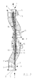
- the apparatus of Fig. 1 is for widening a single lane stream of upright, filled and sealed PET bottles, in the following briefly bottles 1 called, on three tracks and for simultaneous reduction the transport speed to about one third of initial value.
- the device has a feed conveyor 4, the one horizontal conveyor belt 12 in the form of a hinge belt chain with two parallel side rails 2, 3. Between these, the fillers, not shown and closing machine promoted bottles 1 in the by the arrow T marked transport direction with the Speed V1 fed continuously and linearly.
- the device further comprises a discharge conveyor 7, the four Conveyor belts 13 in the form of hinge bands and two parallel side railing 5, 6 comprises. Between these the bottles 1 are in three lanes at the speed V3 to a packaging machine, not shown continuously removed.
- the speed V3 corresponds approximately one third of the speed V1
- the railings 2, 3 of the feed conveyor 4 and the railing 5, 6 of Outlet conveyor 7 are connected by two guides 9, 10 with each other connected defining a transition area 8. In this takes the width of the bottle stream from one Bottle diameter to about three bottle diameter too. Of the Transition region 8 is aligned both with the feed conveyor 4 as also the discharge conveyor 7.
- the broadening of the transport path or the bottle flow takes place in two funnel-like extensions 8a, 8c of Guides 9, 10 between which an area 8b same Width, but wider than the feed conveyor 4, is present.
- This will create a defined and controlled Broadening of the bottle formation in two steps allowing between a reassurance and stabilization the bottle flow takes place.
- This is also at unstable bottles and highest performance reliable, seamless and trouble-free transport realizable.
- This is on the left side of theinternstrom located railing 3, the subsequent Guide 10 and on the left side of the bottle flow railing 6 practically straight in a run, while on the right side of the bottle stream located guide 9 at an angle to the guide 10th extending start and end area and a parallel to Guide 10 extending middle region.
- the Transport path thus extends twice about the same amount to the right side of the transport path out there the basic transport direction T is maintained.
- the conveyor belt 12 is curved and runs in the end of the feed conveyor 4 obliquely to the right under a point Angle to the transport direction T out of the transport path, and then goes in a direction parallel to the transport direction T. arranged, but laterally offset area over.
- the drive motor 15 for the conveyor belt 12th On the left side of the conveyor belt 11 run two also curved conveyor belts 14 with identical Trajectory starting in the area of the feeder 4 and in End of the drive motor 15. They are from this via a reduction gear with a slightly lower Speed driven as the conveyor belt 12.
- the four conveyor belts 13 of the discharge conveyor 7 are curvy and join the left side of the End region of the conveyor belts 14 at. They run in the area 8c also oblique to the transport direction T and contribute to Dump the bottles before putting their in Transport direction running take position.
- the device of Fig. 2 differs from the Device according to Fig. 1 solely in that the extension of the transition region in the region 8c to the left side of the Transport path T out. Accordingly, the Guides, railings and conveyor belts in this area arranged mirror-inverted to Fig. 1.
- the device after FIG. 3 differs from that of FIG. 1 in that only a widening of the bottle flow on two tracks and a reduction of Transport speed is about half. Thereby The second extension area 8c and the area 8b are omitted goes directly to the discharge conveyor 7.
- the obliquely to the transport direction T extending areas of the Conveyor belts 11 to 14 may possibly by appropriately shortened straight-line conveyor belts are replaced, the total obliquely to the transport direction T run. Also can shortened in the apparatus of FIGS. 1 and 2, the area 8b or completely eliminated.
- the device according to FIG. 4 is in principle Structure of the device of FIG. 3 similar, i. in the Transition area 8 is just a single group of total seven adjacent curved conveyor belts 11 with S-shaped course available, although the Curvature opposite to the device according to FIG. 3 runs. Also in the apparatus of Fig. 4 in Transition area 8 on both sides guides 9 ', 10', which the railings 2, 3 of the feed conveyor 4 with the railings 5, 6 of the discharge conveyor 7 continuously connect and so the Lead the bottle stream on both sides.
- the funnel-like widening guides 9 ', 10' not straight but composed of arcuate sections, such that Overall, a slight snake- or S-shaped course the transition region 8 or its two subregions 8a, 8b results.
- the bottles 1 are therefore when passing the Transitional area 8 with respect to the original Transport direction T first slightly to the right, then slightly to the left and then turn slightly to the right, So do not be abrupt, and be on both sides by the guides 9 ', 10' passed.
- the serpentine course of the guides 9 ', 10' is at the S-shaped course of the conveyor belts 11th so matched that in the entire transition area 8 the Conveyor belts 11 at an acute angle to the Guides 9 ', 10' run and thereby the desired Generate transverse pressure for moving the bottles.
- This one is at the device of FIG. 4 optimized such that with a a relatively short length of a reforming a fast-running single-row bottle stream in a slow running four-row bottle stream is possible especially when transporting PET bottles.
- the serpentine transition region about "bulbous" too shape, as indicated by dash-dotted lines in Fig. 4.
Landscapes
- Engineering & Computer Science (AREA)
- Mechanical Engineering (AREA)
- Attitude Control For Articles On Conveyors (AREA)
- Structure Of Belt Conveyors (AREA)
- Control And Other Processes For Unpacking Of Materials (AREA)
- Wrapping Of Specific Fragile Articles (AREA)
- Supplying Of Containers To The Packaging Station (AREA)
Abstract
Description
- Fig. 1
- die Draufsicht auf eine erste Ausführung einer Vorrichtung zum Verbreitern eines Flaschenstroms
- Fig. 2
- die Draufsicht auf eine zweite Ausführung einer Vorrichtung zum Verbreitern eines Flaschenstroms
- Fig. 3
- die Draufsicht auf eine dritte Ausführung einer Vorrichtung zum Verbreitern eines Flaschenstroms.
Claims (5)
- Vorrichtung zum Verbreitern und Verlangsamen eines Stroms aufrechstehender Flaschen (1), mit einem einspurigen, beidseitig mit Geländern (2, 3) versehenen Zuförderer (4), einem mehrspurigen, beidseitig mit Geländern (5, 6) versehenen, langsamer laufenden Abförderer (7) sowie mit die Geländer des Zuförderers und des Abförderers miteinander verbindenden, einen sich in Transportrichtung erweiternden Übergangsbereich (8) bildenden Führungen (9, 10), in dem die Flaschen durch am Boden angreifende Förderbänder (11, 14) oder dgl. reibschlüssig transportiert werden, dadurch gekennzeichnet, dass die Förderbänder (11, 14) im Übergangsbereich (8) zumindest teilweise schräg zur Transportrichtung (T) des Zuförderers (4) verlaufen.
- Vorrichtung nach Anspruch 1, dadurch gekennzeichnet, dass der Zuförderer (4) mit dem Abförderer (7) fluchtet.
- Vorrichtung nach Anspruch 1 oder 2, dadurch gekennzeichnet, dass eine der beiden Führungen (10) mit dem auf der gleichen Seite liegenden Geländer (3) des Zuförderers (4) und dem auf der gleichen Seite liegenden Geländer (6) des Abförderers (7) im wesentlichen fluchtet.
- Vorrichtung nach einem der Ansprüche 1 bis 3, dadurch gekennzeichnet, dass zumindest ein Teil der Förderbänder (11 bis 14) kurvengängig ausgebildet ist und einen jeweils parallel zur Transportrichtung (T) verlaufenden Anfangs- und Endbereich sowie einen schräg zur Transportrichtung (T) verlaufenden Zwischenbereich aufweist.
- Vorrichtung nach Anspruch 1 oder 2, dadurch gekennzeichnet, dass die den sich erweiternden Übergangsbereich (8) bildenden beidseitigen Führungen (9', 10') für die Flaschen (1) einen schlangen- oder S-förmigen Verlauf aufweisen.
Priority Applications (1)
| Application Number | Priority Date | Filing Date | Title |
|---|---|---|---|
| SI200331156T SI1359100T1 (sl) | 2002-04-30 | 2003-02-28 | Naprava za razĺ iritev in upoäśasnitev toka pokonci stojeäśih steklenic |
Applications Claiming Priority (2)
| Application Number | Priority Date | Filing Date | Title |
|---|---|---|---|
| DE20206895U DE20206895U1 (de) | 2002-04-30 | 2002-04-30 | Vorrichtung zum Verbreitern und Verlangsamen eines Stroms aufrechtstehender Flaschen |
| DE20206895U | 2002-04-30 |
Publications (3)
| Publication Number | Publication Date |
|---|---|
| EP1359100A2 true EP1359100A2 (de) | 2003-11-05 |
| EP1359100A3 EP1359100A3 (de) | 2007-03-21 |
| EP1359100B1 EP1359100B1 (de) | 2008-02-20 |
Family
ID=7970721
Family Applications (1)
| Application Number | Title | Priority Date | Filing Date |
|---|---|---|---|
| EP03004577A Expired - Lifetime EP1359100B1 (de) | 2002-04-30 | 2003-02-28 | Vorrichtung zum Verbreitern und Verlangsamen eines Stroms aufrechtstehender Flaschen |
Country Status (5)
| Country | Link |
|---|---|
| EP (1) | EP1359100B1 (de) |
| AT (1) | ATE386700T1 (de) |
| DE (2) | DE20206895U1 (de) |
| ES (1) | ES2301720T3 (de) |
| SI (1) | SI1359100T1 (de) |
Cited By (2)
| Publication number | Priority date | Publication date | Assignee | Title |
|---|---|---|---|---|
| CN104085671A (zh) * | 2014-06-23 | 2014-10-08 | 楚天科技股份有限公司 | 冻干机多行进料系统及其进料方法 |
| CN109051724A (zh) * | 2018-06-27 | 2018-12-21 | 楚天科技股份有限公司 | 用于瓶型容器的装盘机 |
Families Citing this family (1)
| Publication number | Priority date | Publication date | Assignee | Title |
|---|---|---|---|---|
| DE102017114460A1 (de) * | 2017-06-29 | 2019-01-03 | Khs Gmbh | Vorrichtung zum Umformen eines schmalen Behälterstroms in einen breiten Behälterstrom |
Citations (1)
| Publication number | Priority date | Publication date | Assignee | Title |
|---|---|---|---|---|
| DE3505253C2 (de) | 1985-02-15 | 1995-04-27 | Seitz Enzinger Noll Masch | Flaschenverteilstation zum Umformen eines angeförderten einspurigen Flaschenstroms zu einem abzufördernden breiten Flaschenstrom |
Family Cites Families (5)
| Publication number | Priority date | Publication date | Assignee | Title |
|---|---|---|---|---|
| NL7005742A (de) * | 1970-04-21 | 1971-10-25 | ||
| DE3507512A1 (de) * | 1985-03-04 | 1986-09-04 | Seitz Enzinger Noll Maschinenbau Ag, 6800 Mannheim | Anordnung zum umformen eines angefoerderten breiten flaschenstroms zu einem abzufoerdernden einspurigen flaschenstrom |
| DE4129710C2 (de) * | 1991-09-06 | 1997-01-23 | Ortmann & Herbst Masch Gmbh | Vorrichtung zum Verbreitern eines einspurigen Förderstroms aufrechtstehender Behälter |
| DE4213557B4 (de) * | 1992-04-24 | 2004-04-15 | Hermann Kronseder | Verfahren und Vorrichtung zum Umformen einer aufrechtstehend auf einem Fördermittel einspurig aus einer Gefäßbehandlungsmaschine auslaufenden Gefäßreihe |
| CH686569A5 (de) * | 1992-09-02 | 1996-04-30 | Paxona Ag | Verfahren und Vorrichtung zur Flaschenverteilung nach Maschinen mit Einzelflaschenauslauf in Getronkebetrieben. |
-
2002
- 2002-04-30 DE DE20206895U patent/DE20206895U1/de not_active Expired - Lifetime
-
2003
- 2003-02-28 AT AT03004577T patent/ATE386700T1/de active
- 2003-02-28 ES ES03004577T patent/ES2301720T3/es not_active Expired - Lifetime
- 2003-02-28 DE DE50309183T patent/DE50309183D1/de not_active Expired - Lifetime
- 2003-02-28 EP EP03004577A patent/EP1359100B1/de not_active Expired - Lifetime
- 2003-02-28 SI SI200331156T patent/SI1359100T1/sl unknown
Patent Citations (1)
| Publication number | Priority date | Publication date | Assignee | Title |
|---|---|---|---|---|
| DE3505253C2 (de) | 1985-02-15 | 1995-04-27 | Seitz Enzinger Noll Masch | Flaschenverteilstation zum Umformen eines angeförderten einspurigen Flaschenstroms zu einem abzufördernden breiten Flaschenstrom |
Cited By (2)
| Publication number | Priority date | Publication date | Assignee | Title |
|---|---|---|---|---|
| CN104085671A (zh) * | 2014-06-23 | 2014-10-08 | 楚天科技股份有限公司 | 冻干机多行进料系统及其进料方法 |
| CN109051724A (zh) * | 2018-06-27 | 2018-12-21 | 楚天科技股份有限公司 | 用于瓶型容器的装盘机 |
Also Published As
| Publication number | Publication date |
|---|---|
| EP1359100B1 (de) | 2008-02-20 |
| EP1359100A3 (de) | 2007-03-21 |
| SI1359100T1 (sl) | 2008-06-30 |
| DE20206895U1 (de) | 2003-06-12 |
| DE50309183D1 (de) | 2008-04-03 |
| ES2301720T3 (es) | 2008-07-01 |
| ATE386700T1 (de) | 2008-03-15 |
Similar Documents
| Publication | Publication Date | Title |
|---|---|---|
| DE60118948T2 (de) | Überführung von gegenständen zwischen entgegengesetzt angetriebenen förderern | |
| DE60021735T2 (de) | Überführung von gegenständen zwischen entgegengesetzt angetriebenen förderern | |
| DE3202991A1 (de) | Vorrichtung zum verengen und beschleunigen eines stroms aufrechtstehender flaschen o.dgl. | |
| EP2921435B1 (de) | Umlenkvorrichtung für Gegenstände und Verfahren zum Umlenken von Gegenständen | |
| DE3928017A1 (de) | Verfahren und vorrichtung zum umformen eines mehrspurigen behaelterstromes in einen einspurigen behaelterstrom | |
| DE3823228A1 (de) | Verfahren und anordnung zum umformen eines angefoerderten einspurigen behaelterstromes in einen abzufoerdernden mehrspurigen behaelterstrom | |
| DE69318171T2 (de) | Wendevorrichtung mit kontinuierlicher bewegung | |
| EP2314529B1 (de) | Transporteinheit mit Stauröllchenketten | |
| DE202006002351U1 (de) | Vorrichtung zum Auseinanderführen von Gegenständen | |
| EP2366640A2 (de) | Fördereinheit für ein Transportsystem für Artikel | |
| EP0252461B1 (de) | Anordnung zum Umformen eines angeförderten mehrspurigen Flaschenstromes in einen abzufördernden einspurigen Flaschenstrom | |
| EP1359100B1 (de) | Vorrichtung zum Verbreitern und Verlangsamen eines Stroms aufrechtstehender Flaschen | |
| DE20200794U1 (de) | Vorrichtung zum Verteilen von Behältern | |
| DE29617281U1 (de) | Vorrichtung zum Ausrichten von Gegenständen mit länglichem Querschnitt | |
| DE3715577A1 (de) | Verfahren und vorrichtung zum vereinzeln von flaschen | |
| DE3234286A1 (de) | Vorrichtung zum zusammenfuehren und beschleunigen eines stroms aufrecht stehender flaschen oder dgl. | |
| EP0193878B1 (de) | Anordnung zum Umformen eines angeförderten breiten Flaschenstroms zu einem abzufördernden einspurigen Flaschenstrom | |
| DE102004023181B4 (de) | Zuführungsmaschine | |
| EP1328170B1 (de) | Behälter, vorrichtung und verfahren zum transportieren von stabförmigen artikeln der tabakverarbeitenden industrie | |
| DE2919488A1 (de) | Verfahren und vorrichtung zum vereinzeln von im wesentlichen rechteckigen oder quadratischen gefaessen, insbesondere in gefaessbehandlungsmaschinen | |
| EP3722243B1 (de) | Einlaufschiene für fahrtreppen oder fahrsteige sowie personenfördervorrichtung mit einer solchen einlaufschiene | |
| EP3678963A1 (de) | Transportvorrichtung sowie transportverfahren mit einer derartigen transportvorrichtung | |
| DE3007104A1 (de) | Transportvorrichtung fuer aufrecht stehende gefaesse | |
| EP0536703A1 (de) | Anordnung zum Umformen eines angeförderten mehrspurigen Behälterstromes in einen abzufördernden einspurigen Behälterstrom | |
| DE4133588A1 (de) | Anordnung zum umformen eines angefoerderten mehrspurigen behaelterstromes in einen abzufoerdernden einspurigen behaelterstrom |
Legal Events
| Date | Code | Title | Description |
|---|---|---|---|
| PUAI | Public reference made under article 153(3) epc to a published international application that has entered the european phase |
Free format text: ORIGINAL CODE: 0009012 |
|
| AK | Designated contracting states |
Kind code of ref document: A2 Designated state(s): AT BE BG CH CY CZ DE DK EE ES FI FR GB GR HU IE IT LI LU MC NL PT SE SI SK TR |
|
| AX | Request for extension of the european patent |
Extension state: AL LT LV MK RO |
|
| 17P | Request for examination filed |
Effective date: 20040421 |
|
| PUAL | Search report despatched |
Free format text: ORIGINAL CODE: 0009013 |
|
| AK | Designated contracting states |
Kind code of ref document: A3 Designated state(s): AT BE BG CH CY CZ DE DK EE ES FI FR GB GR HU IE IT LI LU MC NL PT SE SI SK TR |
|
| AX | Request for extension of the european patent |
Extension state: AL LT LV MK RO |
|
| GRAP | Despatch of communication of intention to grant a patent |
Free format text: ORIGINAL CODE: EPIDOSNIGR1 |
|
| AKX | Designation fees paid |
Designated state(s): AT BE BG CH CY CZ DE DK EE ES FI FR GB GR HU IE IT LI LU MC NL PT SE SI SK TR |
|
| GRAS | Grant fee paid |
Free format text: ORIGINAL CODE: EPIDOSNIGR3 |
|
| GRAA | (expected) grant |
Free format text: ORIGINAL CODE: 0009210 |
|
| AK | Designated contracting states |
Kind code of ref document: B1 Designated state(s): AT BE BG CH CY CZ DE DK EE ES FI FR GB GR HU IE IT LI LU MC NL PT SE SI SK TR |
|
| REG | Reference to a national code |
Ref country code: GB Ref legal event code: FG4D Free format text: NOT ENGLISH |
|
| REG | Reference to a national code |
Ref country code: CH Ref legal event code: EP Ref country code: CH Ref legal event code: NV Representative=s name: PATENTANWALTSBUERO JEAN HUNZIKER |
|
| REG | Reference to a national code |
Ref country code: IE Ref legal event code: FG4D Free format text: LANGUAGE OF EP DOCUMENT: GERMAN |
|
| REF | Corresponds to: |
Ref document number: 50309183 Country of ref document: DE Date of ref document: 20080403 Kind code of ref document: P |
|
| REG | Reference to a national code |
Ref country code: ES Ref legal event code: FG2A Ref document number: 2301720 Country of ref document: ES Kind code of ref document: T3 |
|
| PG25 | Lapsed in a contracting state [announced via postgrant information from national office to epo] |
Ref country code: FI Free format text: LAPSE BECAUSE OF FAILURE TO SUBMIT A TRANSLATION OF THE DESCRIPTION OR TO PAY THE FEE WITHIN THE PRESCRIBED TIME-LIMIT Effective date: 20080220 |
|
| REG | Reference to a national code |
Ref country code: IE Ref legal event code: FD4D |
|
| ET | Fr: translation filed | ||
| PG25 | Lapsed in a contracting state [announced via postgrant information from national office to epo] |
Ref country code: SE Free format text: LAPSE BECAUSE OF FAILURE TO SUBMIT A TRANSLATION OF THE DESCRIPTION OR TO PAY THE FEE WITHIN THE PRESCRIBED TIME-LIMIT Effective date: 20080520 Ref country code: PT Free format text: LAPSE BECAUSE OF FAILURE TO SUBMIT A TRANSLATION OF THE DESCRIPTION OR TO PAY THE FEE WITHIN THE PRESCRIBED TIME-LIMIT Effective date: 20080721 Ref country code: SK Free format text: LAPSE BECAUSE OF FAILURE TO SUBMIT A TRANSLATION OF THE DESCRIPTION OR TO PAY THE FEE WITHIN THE PRESCRIBED TIME-LIMIT Effective date: 20080220 Ref country code: MC Free format text: LAPSE BECAUSE OF NON-PAYMENT OF DUE FEES Effective date: 20080228 Ref country code: IE Free format text: LAPSE BECAUSE OF FAILURE TO SUBMIT A TRANSLATION OF THE DESCRIPTION OR TO PAY THE FEE WITHIN THE PRESCRIBED TIME-LIMIT Effective date: 20080220 Ref country code: DK Free format text: LAPSE BECAUSE OF FAILURE TO SUBMIT A TRANSLATION OF THE DESCRIPTION OR TO PAY THE FEE WITHIN THE PRESCRIBED TIME-LIMIT Effective date: 20080220 |
|
| PLBE | No opposition filed within time limit |
Free format text: ORIGINAL CODE: 0009261 |
|
| STAA | Information on the status of an ep patent application or granted ep patent |
Free format text: STATUS: NO OPPOSITION FILED WITHIN TIME LIMIT |
|
| 26N | No opposition filed |
Effective date: 20081121 |
|
| PG25 | Lapsed in a contracting state [announced via postgrant information from national office to epo] |
Ref country code: EE Free format text: LAPSE BECAUSE OF FAILURE TO SUBMIT A TRANSLATION OF THE DESCRIPTION OR TO PAY THE FEE WITHIN THE PRESCRIBED TIME-LIMIT Effective date: 20080220 |
|
| PG25 | Lapsed in a contracting state [announced via postgrant information from national office to epo] |
Ref country code: BG Free format text: LAPSE BECAUSE OF FAILURE TO SUBMIT A TRANSLATION OF THE DESCRIPTION OR TO PAY THE FEE WITHIN THE PRESCRIBED TIME-LIMIT Effective date: 20080520 |
|
| PG25 | Lapsed in a contracting state [announced via postgrant information from national office to epo] |
Ref country code: CY Free format text: LAPSE BECAUSE OF FAILURE TO SUBMIT A TRANSLATION OF THE DESCRIPTION OR TO PAY THE FEE WITHIN THE PRESCRIBED TIME-LIMIT Effective date: 20080220 |
|
| PG25 | Lapsed in a contracting state [announced via postgrant information from national office to epo] |
Ref country code: LU Free format text: LAPSE BECAUSE OF NON-PAYMENT OF DUE FEES Effective date: 20080228 Ref country code: HU Free format text: LAPSE BECAUSE OF FAILURE TO SUBMIT A TRANSLATION OF THE DESCRIPTION OR TO PAY THE FEE WITHIN THE PRESCRIBED TIME-LIMIT Effective date: 20080821 |
|
| PG25 | Lapsed in a contracting state [announced via postgrant information from national office to epo] |
Ref country code: TR Free format text: LAPSE BECAUSE OF FAILURE TO SUBMIT A TRANSLATION OF THE DESCRIPTION OR TO PAY THE FEE WITHIN THE PRESCRIBED TIME-LIMIT Effective date: 20080220 |
|
| PG25 | Lapsed in a contracting state [announced via postgrant information from national office to epo] |
Ref country code: GR Free format text: LAPSE BECAUSE OF FAILURE TO SUBMIT A TRANSLATION OF THE DESCRIPTION OR TO PAY THE FEE WITHIN THE PRESCRIBED TIME-LIMIT Effective date: 20080521 |
|
| PGFP | Annual fee paid to national office [announced via postgrant information from national office to epo] |
Ref country code: CZ Payment date: 20110131 Year of fee payment: 9 |
|
| PGFP | Annual fee paid to national office [announced via postgrant information from national office to epo] |
Ref country code: BE Payment date: 20120214 Year of fee payment: 10 |
|
| PGFP | Annual fee paid to national office [announced via postgrant information from national office to epo] |
Ref country code: AT Payment date: 20120126 Year of fee payment: 10 |
|
| PGFP | Annual fee paid to national office [announced via postgrant information from national office to epo] |
Ref country code: SI Payment date: 20130115 Year of fee payment: 11 |
|
| BERE | Be: lapsed |
Owner name: KRONES A.G. Effective date: 20130228 |
|
| REG | Reference to a national code |
Ref country code: AT Ref legal event code: MM01 Ref document number: 386700 Country of ref document: AT Kind code of ref document: T Effective date: 20130228 |
|
| PG25 | Lapsed in a contracting state [announced via postgrant information from national office to epo] |
Ref country code: CZ Free format text: LAPSE BECAUSE OF NON-PAYMENT OF DUE FEES Effective date: 20130228 Ref country code: AT Free format text: LAPSE BECAUSE OF NON-PAYMENT OF DUE FEES Effective date: 20130228 |
|
| PG25 | Lapsed in a contracting state [announced via postgrant information from national office to epo] |
Ref country code: BE Free format text: LAPSE BECAUSE OF NON-PAYMENT OF DUE FEES Effective date: 20130228 |
|
| PG25 | Lapsed in a contracting state [announced via postgrant information from national office to epo] |
Ref country code: SI Free format text: LAPSE BECAUSE OF NON-PAYMENT OF DUE FEES Effective date: 20140301 |
|
| REG | Reference to a national code |
Ref country code: SI Ref legal event code: KO00 Effective date: 20141008 |
|
| REG | Reference to a national code |
Ref country code: FR Ref legal event code: PLFP Year of fee payment: 14 |
|
| REG | Reference to a national code |
Ref country code: FR Ref legal event code: PLFP Year of fee payment: 15 |
|
| REG | Reference to a national code |
Ref country code: FR Ref legal event code: PLFP Year of fee payment: 16 |
|
| PGFP | Annual fee paid to national office [announced via postgrant information from national office to epo] |
Ref country code: NL Payment date: 20180214 Year of fee payment: 16 |
|
| PGFP | Annual fee paid to national office [announced via postgrant information from national office to epo] |
Ref country code: CH Payment date: 20180213 Year of fee payment: 16 Ref country code: GB Payment date: 20180228 Year of fee payment: 16 Ref country code: ES Payment date: 20180301 Year of fee payment: 16 |
|
| PGFP | Annual fee paid to national office [announced via postgrant information from national office to epo] |
Ref country code: IT Payment date: 20190221 Year of fee payment: 17 Ref country code: FR Payment date: 20190111 Year of fee payment: 17 Ref country code: DE Payment date: 20190212 Year of fee payment: 17 |
|
| REG | Reference to a national code |
Ref country code: CH Ref legal event code: PL |
|
| REG | Reference to a national code |
Ref country code: NL Ref legal event code: MM Effective date: 20190301 |
|
| GBPC | Gb: european patent ceased through non-payment of renewal fee |
Effective date: 20190228 |
|
| PG25 | Lapsed in a contracting state [announced via postgrant information from national office to epo] |
Ref country code: CH Free format text: LAPSE BECAUSE OF NON-PAYMENT OF DUE FEES Effective date: 20190228 Ref country code: LI Free format text: LAPSE BECAUSE OF NON-PAYMENT OF DUE FEES Effective date: 20190228 |
|
| PG25 | Lapsed in a contracting state [announced via postgrant information from national office to epo] |
Ref country code: GB Free format text: LAPSE BECAUSE OF NON-PAYMENT OF DUE FEES Effective date: 20190228 Ref country code: NL Free format text: LAPSE BECAUSE OF NON-PAYMENT OF DUE FEES Effective date: 20190301 |
|
| REG | Reference to a national code |
Ref country code: ES Ref legal event code: FD2A Effective date: 20200331 |
|
| PG25 | Lapsed in a contracting state [announced via postgrant information from national office to epo] |
Ref country code: ES Free format text: LAPSE BECAUSE OF NON-PAYMENT OF DUE FEES Effective date: 20190301 |
|
| REG | Reference to a national code |
Ref country code: DE Ref legal event code: R119 Ref document number: 50309183 Country of ref document: DE |
|
| PG25 | Lapsed in a contracting state [announced via postgrant information from national office to epo] |
Ref country code: DE Free format text: LAPSE BECAUSE OF NON-PAYMENT OF DUE FEES Effective date: 20200901 Ref country code: FR Free format text: LAPSE BECAUSE OF NON-PAYMENT OF DUE FEES Effective date: 20200229 |
|
| PG25 | Lapsed in a contracting state [announced via postgrant information from national office to epo] |
Ref country code: IT Free format text: LAPSE BECAUSE OF NON-PAYMENT OF DUE FEES Effective date: 20200228 |