EP1359067A2 - Gurtaufroller für einen Fahrzeug-Sicherheitsgurt - Google Patents
Gurtaufroller für einen Fahrzeug-Sicherheitsgurt Download PDFInfo
- Publication number
- EP1359067A2 EP1359067A2 EP03008755A EP03008755A EP1359067A2 EP 1359067 A2 EP1359067 A2 EP 1359067A2 EP 03008755 A EP03008755 A EP 03008755A EP 03008755 A EP03008755 A EP 03008755A EP 1359067 A2 EP1359067 A2 EP 1359067A2
- Authority
- EP
- European Patent Office
- Prior art keywords
- blocking
- belt
- wheel
- locking
- retractor according
- Prior art date
- Legal status (The legal status is an assumption and is not a legal conclusion. Google has not performed a legal analysis and makes no representation as to the accuracy of the status listed.)
- Granted
Links
Images


Classifications
-
- B—PERFORMING OPERATIONS; TRANSPORTING
- B60—VEHICLES IN GENERAL
- B60R—VEHICLES, VEHICLE FITTINGS, OR VEHICLE PARTS, NOT OTHERWISE PROVIDED FOR
- B60R22/00—Safety belts or body harnesses in vehicles
- B60R22/34—Belt retractors, e.g. reels
- B60R22/44—Belt retractors, e.g. reels with means for reducing belt tension during use under normal conditions
-
- B—PERFORMING OPERATIONS; TRANSPORTING
- B60—VEHICLES IN GENERAL
- B60R—VEHICLES, VEHICLE FITTINGS, OR VEHICLE PARTS, NOT OTHERWISE PROVIDED FOR
- B60R22/00—Safety belts or body harnesses in vehicles
- B60R22/34—Belt retractors, e.g. reels
- B60R22/343—Belt retractors, e.g. reels with electrically actuated locking means
-
- B—PERFORMING OPERATIONS; TRANSPORTING
- B60—VEHICLES IN GENERAL
- B60R—VEHICLES, VEHICLE FITTINGS, OR VEHICLE PARTS, NOT OTHERWISE PROVIDED FOR
- B60R22/00—Safety belts or body harnesses in vehicles
- B60R22/28—Safety belts or body harnesses in vehicles incorporating energy-absorbing devices
- B60R2022/286—Safety belts or body harnesses in vehicles incorporating energy-absorbing devices using deformation of material
- B60R2022/287—Safety belts or body harnesses in vehicles incorporating energy-absorbing devices using deformation of material of torsion rods or tubes
-
- B—PERFORMING OPERATIONS; TRANSPORTING
- B60—VEHICLES IN GENERAL
- B60R—VEHICLES, VEHICLE FITTINGS, OR VEHICLE PARTS, NOT OTHERWISE PROVIDED FOR
- B60R22/00—Safety belts or body harnesses in vehicles
- B60R22/34—Belt retractors, e.g. reels
- B60R22/44—Belt retractors, e.g. reels with means for reducing belt tension during use under normal conditions
- B60R2022/442—Belt retractors, e.g. reels with means for reducing belt tension during use under normal conditions using one spring and one additional retraction device in parallel
- B60R2022/444—Belt retractors, e.g. reels with means for reducing belt tension during use under normal conditions using one spring and one additional retraction device in parallel the additional retraction device being an electric actuator
-
- B—PERFORMING OPERATIONS; TRANSPORTING
- B60—VEHICLES IN GENERAL
- B60R—VEHICLES, VEHICLE FITTINGS, OR VEHICLE PARTS, NOT OTHERWISE PROVIDED FOR
- B60R22/00—Safety belts or body harnesses in vehicles
- B60R22/34—Belt retractors, e.g. reels
- B60R22/341—Belt retractors, e.g. reels comprising energy-absorbing means
- B60R22/3413—Belt retractors, e.g. reels comprising energy-absorbing means operating between belt reel and retractor frame
Definitions
- the invention relates to a belt retractor for a vehicle seat belt, with a frame, a belt reel that is rotatably mounted in the frame, a drive motor that can interact with a drive wheel that with the belt reel is coupled, a locking pawl and locking teeth, into which the locking pawl can be controlled to close the belt spool To block.
- Such a belt retractor is known from DE 100 18 972.
- the pawl is from a spring in the sense of an intervention in the locking teeth applied.
- An electromagnet is provided which is switched on Condition the locking pawl is out of engagement with the locking teeth.
- the object of the invention is the known belt retractor to improve in that there is less construction.
- the beginning of a belt retractor mentioned type provided that the drive wheel limited relative to the belt spool is rotatable and that the locking pawl as a function of this relative rotation is controlled.
- the belt retractor according to the invention is based on the Basic idea, the already existing drive motor for the belt spool can now also be used to control the locking pawl. This happens in that the drive motor is controlled so that the control of the Locking pawl required relative rotation between the drive wheel and the Belt reel results. This makes it possible to dispense with additional components that were previously required to operate the locking pawl.
- the locking teeth on one Blocking wheel is formed, which is fixedly connected to the belt spool, and that at least one return spring between the drive wheel and the blocking wheel is provided which the drive wheel relative to the blocking wheel in a Starting position applied.
- the locking pawl of a locking spring permanently in the sense of an intervention in the locking teeth acted upon, wherein the drive wheel is provided with a control toothing, the through depressions in the otherwise smooth outer peripheral surface of the Drive wheel is formed, and wherein the locking teeth and the Control teeth are designed so that in the starting position between Drive wheel and blocking wheel the outer peripheral surface of the drive wheel prevents the locking pawl from being driven into the locking teeth.
- the return spring can be dimensioned so that the drag torque of the currentless drive motor is greater than the torque required to turn of the drive wheel relative to the blocking wheel is required. That way achieves an emergency running lock, which the belt spool then in the webbing take-off direction locks when the drive motor stops.
- the return spring can also be dimensioned to such a degree that when slowly subtracting Belt webbing from the belt spool does not make a relative rotation between the drive wheel and blocking wheel comes, but only when a predetermined one is exceeded Rotational acceleration of the belt reel, because in this case the rotational moment of inertia of the drive motor also acts as a brake. In this way can be realized a blocking function that a conventional mechanical, webbing sensitive blocking corresponds.
- flank of the locking teeth interacting with the locking pawl is not undercut. This enables the control toothing of the drive wheel, the blocking pawl from the blocking teeth when the belt reel is blocked to control without the belt spool in the webbing winding direction for this purpose must be turned; such a rotation would be from Vehicle occupants as a disturbing, brief increase in the webbing force felt.
- a winding spring is provided which the belt reel in the Belt winding direction with a torque that is larger than the drag torque of the drive motor when it is de-energized. This too ensures an emergency running function in that when the electrical supply to the drive motor or in the event of its failure Control in any case ensures that the webbing is working properly is wound up when the vehicle occupant removes the seat belt.
- An electronic control unit is preferably provided, which Drive motor controls so that when pulling or winding the webbing always a predetermined webbing force acts.
- the control unit recognizes the Rotation of the belt spool, for example by means of a belt spool sensor, and controls the drive motor and thus the rotation of the belt reel so that Belt strap is available in the desired manner. If the The vehicle's occupant, for example, puts on the seat belt, the drive motor a torque ready that matches the torque of the take-up spring is opposite. This results in a comparatively low one Gurtbandabzugskraft.
- the torque provided by the drive motor is preferably varies so that a constant for the vehicle occupant Webbing pull-off force is noticeable, although that exerted by the take-up spring Torque increases with increasing webbing withdrawal.
- the drive motor can also provide a torque when winding the webbing that the Counteracts the torque of the winding spring. In this way the comparatively high webbing winding force of the winding spring on Comfortable size reduced.
- the control unit can have a signal input for vehicle acceleration have, the control unit when exceeding a predetermined Vehicle acceleration controls the drive motor so that the drive wheel is brought into a blocking position relative to the blocking wheel, in which the Locking pawl engages in the locking teeth.
- the signal for the Vehicle acceleration can come from existing systems, for example an electronic stability program or an anti-lock braking system, and the control unit via a vehicle bus system, for example a CAN bus. In this way, with little Realize the vehicle-sensitive blocking of the belt spool.
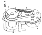
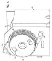
- FIGS. 1 and 2 show a belt retractor that has a frame 10 and has a belt spool 12 rotatably mounted in the frame.
- a vehicle seat belt can be added on the belt reel 12 .
- Inside the Belt reel 12 has a torsion bar 14 arranged on it with respect to FIG left end is rotatably connected to the belt spool 12. At this end too a winding spring 16 connected which the belt reel 12 in the webbing winding direction applied.
- a blocking wheel 18 is rotatably connected.
- the blocking wheel 18 has a smooth outer peripheral surface that is periodically spaced from Wells 20 is interrupted.
- the depressions 20 have a radial Direction-oriented flank and an oblique from the lowest point of the Deepening to the outer peripheral surface, the radial aligned flank is the one that occurs when the belt reel 12 and so that the blocking wheel 18 lies in the rear in the webbing unwinding direction. All Recesses 20 together form blocking teeth on the blocking wheel 18.
- a drive wheel 22 is arranged concentrically on the blocking wheel 18 is provided with two recesses 24.
- a tab engages in each recess 24 26, which are formed on the blocking wheel 18.
- a return spring 28 (see Figure 3) arranged that the drive wheel 22 relative to the blocking wheel 18 in a in Figure 3 Apply shown starting position.
- the drive wheel 22 is on his Outer peripheral surface in the same way as the blocking wheel 18 with several Provide depressions, which are provided here with the reference numeral 30.
- the depressions 30 of the drive wheel 22 with two approximately symmetrically arranged, obliquely extending flanks so that a control toothing is formed.
- the drive motor 36 is preferably a synchronous external rotor motor.
- the drive motor will controlled by a schematically illustrated control unit 38, the signals from a schematically illustrated vehicle acceleration sensor 40 and one schematically shown belt reel sensor 44 receives the rotation of the Belt reel detected.
- Two locking pawls 46 are attached to the frame 10 of the belt retractor, the each other with respect to the axis of rotation of the blocking wheel 18 and the drive wheel 22 diametrically opposite.
- the two pawls 46 can in the Locking teeth of the blocking wheel 18 are controlled. To this end they are in the sense of a blocking spring 48 (indicated in Figure 3) an engagement in the locking teeth of the locking wheel 18 is applied.
- the mode of operation of the Belt retractor described. It starts from an equilibrium state, where the webbing forces, the torque of the winding spring and the torque of the drive motor are in balance, so that the Belt reel does not turn. Since the winding spring 16 is dimensioned so that it at de-energized drive motor 36 rotate the belt reel in the winding direction For this equilibrium state, the drive motor 36 is required the torque of the winding spring largely compensated.
- the drive motor So tries to counter the drive wheel with respect to FIG To turn clockwise. This alone makes the drive wheel 22 relatively to the blocking wheel 18 in the starting position shown in FIG characterized in that the recesses 20 of the blocking wheel 18 offset the recesses 30 of the drive wheel 22 are arranged. Expressed differently the recesses of a wheel are always in an angular range, in which the other wheel has a smooth outer peripheral surface.
- the drive motor is controlled so that the drive wheel 22nd is rotated counterclockwise with respect to Figure 4.
- the run corresponding flanks of the recesses 30 of the drive wheel 22 on the tips the pawls 46 and push them radially outward until they come out of the Locking teeth of the blocking wheel 18 are controlled. It is not here required, the belt spool slightly in the webbing winding direction turn because the flanks of the locking teeth on which the locking pawls 46 are radially aligned.
- the blocking is removed as soon as the pawls 46 on the smooth outer peripheral surface of the drive wheel 22 lie on and leave the corresponding recess 20 of the blocking wheel 18 to have.
- a large number of convenience functions can be performed by means of the control unit 38 Realize in normal operation of the belt retractor. For example, ensure that the webbing take-up force when putting on the belt is lower than when taking off or even while driving depending on the driving style changes. Furthermore, it can be ensured that the Webbing winding force regardless of the length of the already wound Webbing does not change.
Abstract
Description
- Figur 1 in einer schematischen Explosionsansicht einen erfindungsgemäßen Gurtaufroller;
- Figur 2 in einer perspektivischen, schematischen Ansicht den Gurtaufroller von Figur 1, wobei zur besseren Übersichtlichkeit einige Bauteile nicht dargestellt sind;
- Figur 3 in einer perspektivischen, vergrößerten Ansicht den Blockiermechanismus des Gurtaufrollers von Figur 2 im nicht blockierten Zustand;
- Figur 4 den Blockiermechanismus von Figur 3 im blockierten Zustand; und
- Figur 5 ein Diagramm des Verlaufs der Gurtbandabzugskraft, der Federkennlinie der Aufwickelfeder sowie des Drehmoments des Antriebsmotors bei verschiedenen Betriebszuständen.
Claims (14)
- Gurtaufroller für einen Fahrzeug-Sicherheitsgurt, mit einem Rahmen (10), einer Gurtspule (12), die drehbar in dem Rahmen (10) angebracht ist, einem Antriebsmotor (36), der mit einem Antriebsrad (22) zusammenwirken kann, das mit der Gurtspule (12) gekoppelt ist, einer Blockierklinke (46) und einer Blockierverzahnung (20), in welche die Blockierklinke (46) eingesteuert werden kann, um die Gurtspule (12) zu blockieren, dadurch gekennzeichnet, daß das Antriebsrad (22) relativ zur Gurtspule begrenzt verdrehbar ist und daß die Blockierklinke (46) in Abhängigkeit von dieser Relativdrehung gesteuert wird.
- Gurtaufroller nach Anspruch 1, dadurch gekennzeichnet, daß die Blockierverzahnung (20) an einem Blockierrad (18) ausgebildet ist, das fest mit der Gurtspule (12) verbunden ist, und daß zwischen dem Antriebsrad (22) und dem Blockierrad (18) mindestens eine Rückstellfeder (28) vorgesehen ist, die das Antriebsrad relativ zum Blockierrad in eine Ausgangsstellung beaufschlagt.
- Gurtaufroller nach Anspruch 2, dadurch gekennzeichnet, daß das Blockierrad (18) mit der Gurtspule (12) durch einen Torsionsstab (14) verbunden ist.
- Gurtaufroller nach einem der vorhergehenden Ansprüche, dadurch gekennzeichnet, daß die Blockierklinke (46) von einer Blockierfeder (48) permanent im Sinne eines Eingriffs in die Blockierverzahnung (20) beaufschlagt wird, daß das Antriebsrad (22) mit einer Steuerverzahnung (30) versehen ist, die durch Vertiefungen (30) in der ansonsten glatten Außenumfangsfläche des Antriebsrades (22) gebildet ist, und daß die Blockierverzahnung (20) und die Steuerverzahnung (30) so ausgebildet sind, daß in der Ausgangsstellung zwischen Antriebsrad (22) und Blockierrad (18) die Außenumfangsfläche des Antriebsrades (22) verhindert, daß die Blockierklinke (46) in die Blockierverzahnung (20) eingesteuert wird.
- Gurtaufroller nach Anspruch 3, dadurch gekennzeichnet, daß das Blockierrad (18) eine Außenumfangsfläche aufweist, die zwischen den die Blockierverzahnung bildenden Vertiefungen (20) glatt ist, und daß sich die Blockierklinke (46) an der glatten Außenumfangsfläche abstützen kann.
- Gurtaufroller nach einem der vorhergehenden Ansprüche, dadurch gekennzeichnet, daß die Blockierklinke (46) schwenkbar am Rahmen (10) angebracht ist.
- Gurtaufroller nach einem der vorhergehenden Ansprüche, dadurch gekennzeichnet, daß die mit der Blockierklinke (46) zusammenwirkende Flanke der Blockierverzahnung (20) nicht hinterschnitten ist.
- Gurtaufroller nach einem der vorhergehenden Ansprüche, dadurch gekennzeichnet, daß die Rückstellfeder (28) in Abhängigkeit vom Schleppmoment des Antriebsmotors (36), wenn dieser stromlos ist, und vom Rotations-Trägheitsmoment des Antriebsmotors (36) so dimensioniert ist, daß eine Relativdrehung zwischen dem Antriebsrad (22) und dem Blockierrad (18) erst dann auftritt, wenn die Drehbeschleunigung der Gurtspule (12) in der Gurtband-Abzugsrichtung einen vorbestimmten Grenzwert überschreitet.
- Gurtaufroller nach einem der vorhergehenden Ansprüche, dadurch gekennzeichnet, daß die Rückstellfeder (28) in Abhängigkeit vom Schleppmoment des Antriebsmotors (36), wenn dieser stromlos ist, so dimensioniert ist, daß eine Relativdrehung zwischen dem Antriebsrad (22) und dem Blockierrad (18) dann auftritt, wenn die Gurtspule (12) in der Gurtband-Abzugsrichtung gedreht wird.
- Gurtaufroller nach einem der vorhergehenden Ansprüche, dadurch gekennzeichnet, daß eine Aufwickelfeder (16) vorgesehen ist, welche die Gurtspule (12) in der Gurtband-Aufwickelrichtung mit einem Drehmoment beaufschlagt, das größer ist als das Schleppmoment des Antriebsmotors (36), wenn dieser stromlos ist.
- Gurtaufroller nach einem der vorhergehenden Ansprüche, dadurch gekennzeichnet, daß eine elektronische Steuereinheit (38) vorgesehen ist, die den Antriebsmotor (36) so steuert, daß beim Abziehen bzw. Aufwickeln des Gurtbandes immer eine vorbestimmte Gurtbandkraft wirkt.
- Gurtaufroller nach einem der vorhergehenden Ansprüche, dadurch gekennzeichnet, daß die Steuereinheit ein Signal von einem Fahrzeugbeschleunigungssensor (40) empfangen kann und beim Überschreiten einer vorbestimmten Fahrzeugbeschleunigung den Antriebsmotor (36) so steuert, daß das Antriebsrad (22) relativ zum Blockierrad (18) in eine Blockierstellung gebracht wird, in der die Blockierklinke (46) in die Blockierverzahnung (20) eingreift.
- Gurtaufroller nach einem der vorhergehenden Ansprüche, dadurch gekennzeichnet, daß die Steuereinheit ein Signal von einem Gurtspulen-Sensor (44) empfangen kann, von welchem ausgehend die Drehbeschleunigung der Gurtspule (12) bestimmt wird, und daß die Steuereinheit (38) beim Überschreiten einer vorbestimmten Drehbeschleunigung der Gurtspule (12) den Antriebsmotor (36) so steuert, daß das Antriebsrad (22) relativ zum Blockierrad (18) in eine Blockierstellung gebracht wird, in der die Blockierklinke (46) in die Blockierverzahnung (20) eingreift.
- Gurtaufroller nach Anspruch 13, dadurch gekennzeichnet, daß der Gurtspulen-Sensor (44) ein Hall-Sensor ist.
Applications Claiming Priority (2)
| Application Number | Priority Date | Filing Date | Title |
|---|---|---|---|
| DE20206667U DE20206667U1 (de) | 2002-04-26 | 2002-04-26 | Gurtaufroller für einen Fahrzeug-Sicherheitsgurt |
| DE20206667U | 2002-04-26 |
Publications (3)
| Publication Number | Publication Date |
|---|---|
| EP1359067A2 true EP1359067A2 (de) | 2003-11-05 |
| EP1359067A3 EP1359067A3 (de) | 2004-03-24 |
| EP1359067B1 EP1359067B1 (de) | 2005-08-03 |
Family
ID=7970586
Family Applications (1)
| Application Number | Title | Priority Date | Filing Date |
|---|---|---|---|
| EP03008755A Expired - Lifetime EP1359067B1 (de) | 2002-04-26 | 2003-04-17 | Gurtaufroller für einen Fahrzeug-Sicherheitsgurt |
Country Status (5)
| Country | Link |
|---|---|
| US (1) | US6848645B2 (de) |
| EP (1) | EP1359067B1 (de) |
| JP (1) | JP3795474B2 (de) |
| CN (1) | CN100354162C (de) |
| DE (2) | DE20206667U1 (de) |
Families Citing this family (13)
| Publication number | Priority date | Publication date | Assignee | Title |
|---|---|---|---|---|
| JP2004042782A (ja) * | 2002-07-11 | 2004-02-12 | Tokai Rika Co Ltd | ウエビング巻取装置 |
| DE20311004U1 (de) * | 2003-07-17 | 2003-12-04 | Trw Occupant Restraint Systems Gmbh & Co. Kg | Gurtaufroller für einen Fahrzeug-Sicherheitsgurt |
| ES2366560T3 (es) * | 2003-11-27 | 2011-10-21 | Autoliv Development Ab | Medio de retracción para un cinturón de seguridad. |
| DE202004007307U1 (de) * | 2004-05-07 | 2004-09-16 | Trw Automotive Gmbh | Gurtaufroller |
| JP4580253B2 (ja) * | 2005-02-21 | 2010-11-10 | 株式会社東海理化電機製作所 | ウエビング巻取装置 |
| JP2006290087A (ja) * | 2005-04-08 | 2006-10-26 | Takata Corp | シートベルトリトラクタおよびこれを備えたシートベルト装置 |
| JP4640963B2 (ja) * | 2005-08-04 | 2011-03-02 | タカタ株式会社 | シートベルトリトラクタおよびこれを備えたシートベルト装置 |
| JP5261736B2 (ja) * | 2008-09-16 | 2013-08-14 | タカタ株式会社 | シートベルトリトラクタおよびこれを備えたシートベルト装置 |
| JP5452186B2 (ja) * | 2009-11-24 | 2014-03-26 | 株式会社東海理化電機製作所 | 係合部材支持構造及びウエビング巻取装置 |
| US9150193B2 (en) * | 2012-06-14 | 2015-10-06 | Autoliv Asp, Inc. | Mode detection switch assembly for self-locking dual-mode seat belt retractor |
| DE102012107557B3 (de) * | 2012-08-17 | 2014-10-30 | Autoliv Development Ab | Gurtaufroller mit einer schaltbaren Kraftbegrenzungseinrichtung |
| KR101593414B1 (ko) * | 2014-06-09 | 2016-02-12 | 주식회사 우신세이프티시스템 | 시트벨트용 전자식 리트랙터 |
| US10086794B2 (en) * | 2015-06-23 | 2018-10-02 | Ford Global Technologies, Llc | Load limiting retractor with hall effect switch |
Citations (4)
| Publication number | Priority date | Publication date | Assignee | Title |
|---|---|---|---|---|
| FR2696693A1 (fr) * | 1992-10-09 | 1994-04-15 | Autoliv Klippan Snc | Enrouleur de sangle de ceinture de sécurité de véhicule. |
| DE19513724A1 (de) * | 1995-04-11 | 1996-10-17 | Trw Repa Gmbh | Gurtaufroller für ein Fahrzeugsicherheitsgurtsystem |
| EP0972684A1 (de) * | 1998-07-13 | 2000-01-19 | TRW Occupant Restraint Systems GmbH & Co. KG | Sperrmechanismus für einen Sicherheitsgurtaufroller |
| DE10018972A1 (de) * | 2000-04-17 | 2001-10-25 | Trw Automotive Electron & Comp | Gurtaufroller |
Family Cites Families (4)
| Publication number | Priority date | Publication date | Assignee | Title |
|---|---|---|---|---|
| US4765559A (en) * | 1987-07-07 | 1988-08-23 | American Safety Equipment Corporation | Synchronized safety belt retractor with structural control locking means |
| CN1100043A (zh) * | 1993-09-10 | 1995-03-15 | 高田株式会社 | 安全带收缩器 |
| JP4467688B2 (ja) * | 1999-01-19 | 2010-05-26 | タカタ株式会社 | シートベルト巻取装置 |
| DE10020245C2 (de) * | 2000-04-25 | 2002-02-14 | Breed Automotive Tech | Gurtaufroller für einen Fahrzeugsicherheitsgurt |
-
2002
- 2002-04-26 DE DE20206667U patent/DE20206667U1/de not_active Expired - Lifetime
-
2003
- 2003-04-17 EP EP03008755A patent/EP1359067B1/de not_active Expired - Lifetime
- 2003-04-17 DE DE50300890T patent/DE50300890D1/de not_active Expired - Lifetime
- 2003-04-21 US US10/419,567 patent/US6848645B2/en not_active Expired - Lifetime
- 2003-04-25 CN CNB031232779A patent/CN100354162C/zh not_active Expired - Lifetime
- 2003-04-28 JP JP2003123754A patent/JP3795474B2/ja not_active Expired - Fee Related
Patent Citations (4)
| Publication number | Priority date | Publication date | Assignee | Title |
|---|---|---|---|---|
| FR2696693A1 (fr) * | 1992-10-09 | 1994-04-15 | Autoliv Klippan Snc | Enrouleur de sangle de ceinture de sécurité de véhicule. |
| DE19513724A1 (de) * | 1995-04-11 | 1996-10-17 | Trw Repa Gmbh | Gurtaufroller für ein Fahrzeugsicherheitsgurtsystem |
| EP0972684A1 (de) * | 1998-07-13 | 2000-01-19 | TRW Occupant Restraint Systems GmbH & Co. KG | Sperrmechanismus für einen Sicherheitsgurtaufroller |
| DE10018972A1 (de) * | 2000-04-17 | 2001-10-25 | Trw Automotive Electron & Comp | Gurtaufroller |
Also Published As
| Publication number | Publication date |
|---|---|
| CN1453163A (zh) | 2003-11-05 |
| CN100354162C (zh) | 2007-12-12 |
| EP1359067A3 (de) | 2004-03-24 |
| US6848645B2 (en) | 2005-02-01 |
| DE50300890D1 (de) | 2005-09-08 |
| JP2003335218A (ja) | 2003-11-25 |
| US20030201359A1 (en) | 2003-10-30 |
| JP3795474B2 (ja) | 2006-07-12 |
| EP1359067B1 (de) | 2005-08-03 |
| DE20206667U1 (de) | 2002-09-05 |
Similar Documents
| Publication | Publication Date | Title |
|---|---|---|
| EP2084042B1 (de) | Sicherheitsgurtaufroller mit abschaltung seines gurtbandsensitiven und seines fahrzeugsensitiven steuersystems | |
| DE10058932B4 (de) | Fahrgastzurückhaltendes Schutzsystem | |
| EP1359067B1 (de) | Gurtaufroller für einen Fahrzeug-Sicherheitsgurt | |
| DE10039364C2 (de) | Vorrichtung zum Aufrollen eines Sicherheitsgurtes | |
| DE102004010835A1 (de) | Sitzgurtvorrichtung | |
| DE3507792A1 (de) | Rueckziehvorrichtung fuer einen sicherheitsgurt mit automatischer arretierung | |
| DE2429368A1 (de) | Verriegelungsvorrichtung fuer einen fahrzeug-sicherheitsgurt | |
| EP2456641B1 (de) | Gurtaufroller für einen fahrzeugsicherheitsgurt | |
| DE10360032B4 (de) | Gurtaufroller für einen Fahrzeug-Sicherheitsgurt | |
| EP0560176B1 (de) | Sicherheitsgurt-Rückhaltesystem für Fahrzeuge | |
| DE102011101965B4 (de) | Gurtaufroller mit Steuerverzahnung | |
| DE10085153B4 (de) | Sicherheitsgurtvorrichtung mit Sicherheitsgurtretraktor mit Verriegelungsvorrichtung | |
| EP0625449B2 (de) | Sicherheitsgurtaufrollautomat | |
| EP1391357B1 (de) | Gurtvorrichtung | |
| DE3509254C2 (de) | ||
| DE112012001047B4 (de) | Gurtaufroller für einen Sicherheitsgurt | |
| DE102004022134A1 (de) | Gurtaufroller für einen Fahrzeugsicherheitsgurt | |
| DE10352025B4 (de) | Gurtaufroller | |
| EP1501708B1 (de) | Sicherheitsgurtaufroller mit abschaltbarem fahrzeugsensor | |
| DE10139816C2 (de) | Gurtaufroller für einen Sicherheitsgurt eines Fahrzeugs | |
| DE102005011904B4 (de) | Gurtaufroller für einen Sicherheitsgurt | |
| DE2648429C2 (de) | Einziehvorrichtung mit Zugentlastung für Sicherheitsgurte | |
| DE112012002053B4 (de) | Gurtaufroller mit Kindersicherung | |
| DE102008009771B4 (de) | Gurtaufroller für einen Fahrzeug-Sicherheitsgurt | |
| DE10358561A1 (de) | Gurtaufroller für einen Fahrzeug-Sicherheitsgurt |
Legal Events
| Date | Code | Title | Description |
|---|---|---|---|
| PUAI | Public reference made under article 153(3) epc to a published international application that has entered the european phase |
Free format text: ORIGINAL CODE: 0009012 |
|
| AK | Designated contracting states |
Kind code of ref document: A2 Designated state(s): AT BE BG CH CY CZ DE DK EE ES FI FR GB GR HU IE IT LI LU MC NL PT RO SE SI SK TR |
|
| AX | Request for extension of the european patent |
Extension state: AL LT LV MK |
|
| PUAL | Search report despatched |
Free format text: ORIGINAL CODE: 0009013 |
|
| AK | Designated contracting states |
Kind code of ref document: A3 Designated state(s): AT BE BG CH CY CZ DE DK EE ES FI FR GB GR HU IE IT LI LU MC NL PT RO SE SI SK TR |
|
| AX | Request for extension of the european patent |
Extension state: AL LT LV MK |
|
| RIC1 | Information provided on ipc code assigned before grant |
Ipc: 7B 60R 22/405 B Ipc: 7B 60R 22/343 A Ipc: 7B 60R 22/46 B |
|
| 17P | Request for examination filed |
Effective date: 20040622 |
|
| AKX | Designation fees paid |
Designated state(s): DE FR GB IT |
|
| GRAP | Despatch of communication of intention to grant a patent |
Free format text: ORIGINAL CODE: EPIDOSNIGR1 |
|
| GRAS | Grant fee paid |
Free format text: ORIGINAL CODE: EPIDOSNIGR3 |
|
| RBV | Designated contracting states (corrected) |
Designated state(s): DE FR GB IT |
|
| GRAA | (expected) grant |
Free format text: ORIGINAL CODE: 0009210 |
|
| AK | Designated contracting states |
Kind code of ref document: B1 Designated state(s): DE FR GB IT |
|
| REG | Reference to a national code |
Ref country code: GB Ref legal event code: FG4D Free format text: NOT ENGLISH |
|
| REF | Corresponds to: |
Ref document number: 50300890 Country of ref document: DE Date of ref document: 20050908 Kind code of ref document: P |
|
| GBT | Gb: translation of ep patent filed (gb section 77(6)(a)/1977) |
Effective date: 20051003 |
|
| ET | Fr: translation filed | ||
| PLBE | No opposition filed within time limit |
Free format text: ORIGINAL CODE: 0009261 |
|
| STAA | Information on the status of an ep patent application or granted ep patent |
Free format text: STATUS: NO OPPOSITION FILED WITHIN TIME LIMIT |
|
| 26N | No opposition filed |
Effective date: 20060504 |
|
| PGFP | Annual fee paid to national office [announced via postgrant information from national office to epo] |
Ref country code: FR Payment date: 20090417 Year of fee payment: 7 Ref country code: IT Payment date: 20090422 Year of fee payment: 7 |
|
| PGFP | Annual fee paid to national office [announced via postgrant information from national office to epo] |
Ref country code: GB Payment date: 20090415 Year of fee payment: 7 |
|
| GBPC | Gb: european patent ceased through non-payment of renewal fee |
Effective date: 20100417 |
|
| REG | Reference to a national code |
Ref country code: FR Ref legal event code: ST Effective date: 20101230 |
|
| PG25 | Lapsed in a contracting state [announced via postgrant information from national office to epo] |
Ref country code: GB Free format text: LAPSE BECAUSE OF NON-PAYMENT OF DUE FEES Effective date: 20100417 Ref country code: IT Free format text: LAPSE BECAUSE OF NON-PAYMENT OF DUE FEES Effective date: 20100417 |
|
| PG25 | Lapsed in a contracting state [announced via postgrant information from national office to epo] |
Ref country code: FR Free format text: LAPSE BECAUSE OF NON-PAYMENT OF DUE FEES Effective date: 20100430 |
|
| REG | Reference to a national code |
Ref country code: DE Ref legal event code: R081 Ref document number: 50300890 Country of ref document: DE Owner name: TRW AUTOMOTIVE GMBH, DE Free format text: FORMER OWNER: TRW AUTOMOTIVE ELECTRONICS & COMPONENTS GMBH & CO. KG, 78315 RADOLFZELL, DE Ref country code: DE Ref legal event code: R082 Ref document number: 50300890 Country of ref document: DE Representative=s name: PRINZ & PARTNER MBB PATENTANWAELTE RECHTSANWAE, DE |
|
| PGFP | Annual fee paid to national office [announced via postgrant information from national office to epo] |
Ref country code: DE Payment date: 20220427 Year of fee payment: 20 |
|
| REG | Reference to a national code |
Ref country code: DE Ref legal event code: R071 Ref document number: 50300890 Country of ref document: DE |
|
| P01 | Opt-out of the competence of the unified patent court (upc) registered |
Effective date: 20230628 |