EP1357325B1 - Schnellkupplung - Google Patents
Schnellkupplung Download PDFInfo
- Publication number
- EP1357325B1 EP1357325B1 EP03007627A EP03007627A EP1357325B1 EP 1357325 B1 EP1357325 B1 EP 1357325B1 EP 03007627 A EP03007627 A EP 03007627A EP 03007627 A EP03007627 A EP 03007627A EP 1357325 B1 EP1357325 B1 EP 1357325B1
- Authority
- EP
- European Patent Office
- Prior art keywords
- pressure
- relief
- quick coupling
- pressure relief
- coupling
- Prior art date
- Legal status (The legal status is an assumption and is not a legal conclusion. Google has not performed a legal analysis and makes no representation as to the accuracy of the status listed.)
- Expired - Lifetime
Links
- 238000010168 coupling process Methods 0.000 title claims abstract description 152
- 230000008878 coupling Effects 0.000 title claims abstract description 146
- 238000005859 coupling reaction Methods 0.000 title claims abstract description 146
- 238000007789 sealing Methods 0.000 claims description 27
- 238000006073 displacement reaction Methods 0.000 claims description 7
- 150000001875 compounds Chemical class 0.000 description 1
- 239000000356 contaminant Substances 0.000 description 1
- 238000007599 discharging Methods 0.000 description 1
- 230000000694 effects Effects 0.000 description 1
- 239000007789 gas Substances 0.000 description 1
- 239000010720 hydraulic oil Substances 0.000 description 1
- 238000012432 intermediate storage Methods 0.000 description 1
- 239000007788 liquid Substances 0.000 description 1
- 238000000926 separation method Methods 0.000 description 1
- 238000003860 storage Methods 0.000 description 1
- 230000001360 synchronised effect Effects 0.000 description 1
Images


Classifications
-
- F—MECHANICAL ENGINEERING; LIGHTING; HEATING; WEAPONS; BLASTING
- F16—ENGINEERING ELEMENTS AND UNITS; GENERAL MEASURES FOR PRODUCING AND MAINTAINING EFFECTIVE FUNCTIONING OF MACHINES OR INSTALLATIONS; THERMAL INSULATION IN GENERAL
- F16L—PIPES; JOINTS OR FITTINGS FOR PIPES; SUPPORTS FOR PIPES, CABLES OR PROTECTIVE TUBING; MEANS FOR THERMAL INSULATION IN GENERAL
- F16L37/00—Couplings of the quick-acting type
- F16L37/56—Couplings of the quick-acting type for double-walled or multi-channel pipes or pipe assemblies
-
- F—MECHANICAL ENGINEERING; LIGHTING; HEATING; WEAPONS; BLASTING
- F16—ENGINEERING ELEMENTS AND UNITS; GENERAL MEASURES FOR PRODUCING AND MAINTAINING EFFECTIVE FUNCTIONING OF MACHINES OR INSTALLATIONS; THERMAL INSULATION IN GENERAL
- F16L—PIPES; JOINTS OR FITTINGS FOR PIPES; SUPPORTS FOR PIPES, CABLES OR PROTECTIVE TUBING; MEANS FOR THERMAL INSULATION IN GENERAL
- F16L37/00—Couplings of the quick-acting type
- F16L37/28—Couplings of the quick-acting type with fluid cut-off means
- F16L37/30—Couplings of the quick-acting type with fluid cut-off means with fluid cut-off means in each of two pipe-end fittings
-
- Y—GENERAL TAGGING OF NEW TECHNOLOGICAL DEVELOPMENTS; GENERAL TAGGING OF CROSS-SECTIONAL TECHNOLOGIES SPANNING OVER SEVERAL SECTIONS OF THE IPC; TECHNICAL SUBJECTS COVERED BY FORMER USPC CROSS-REFERENCE ART COLLECTIONS [XRACs] AND DIGESTS
- Y10—TECHNICAL SUBJECTS COVERED BY FORMER USPC
- Y10S—TECHNICAL SUBJECTS COVERED BY FORMER USPC CROSS-REFERENCE ART COLLECTIONS [XRACs] AND DIGESTS
- Y10S285/00—Pipe joints or couplings
- Y10S285/924—Vented
-
- Y—GENERAL TAGGING OF NEW TECHNOLOGICAL DEVELOPMENTS; GENERAL TAGGING OF CROSS-SECTIONAL TECHNOLOGIES SPANNING OVER SEVERAL SECTIONS OF THE IPC; TECHNICAL SUBJECTS COVERED BY FORMER USPC CROSS-REFERENCE ART COLLECTIONS [XRACs] AND DIGESTS
- Y10—TECHNICAL SUBJECTS COVERED BY FORMER USPC
- Y10T—TECHNICAL SUBJECTS COVERED BY FORMER US CLASSIFICATION
- Y10T137/00—Fluid handling
- Y10T137/8593—Systems
- Y10T137/87153—Plural noncommunicating flow paths
-
- Y—GENERAL TAGGING OF NEW TECHNOLOGICAL DEVELOPMENTS; GENERAL TAGGING OF CROSS-SECTIONAL TECHNOLOGIES SPANNING OVER SEVERAL SECTIONS OF THE IPC; TECHNICAL SUBJECTS COVERED BY FORMER USPC CROSS-REFERENCE ART COLLECTIONS [XRACs] AND DIGESTS
- Y10—TECHNICAL SUBJECTS COVERED BY FORMER USPC
- Y10T—TECHNICAL SUBJECTS COVERED BY FORMER US CLASSIFICATION
- Y10T137/00—Fluid handling
- Y10T137/8593—Systems
- Y10T137/87153—Plural noncommunicating flow paths
- Y10T137/87161—With common valve operator
-
- Y—GENERAL TAGGING OF NEW TECHNOLOGICAL DEVELOPMENTS; GENERAL TAGGING OF CROSS-SECTIONAL TECHNOLOGIES SPANNING OVER SEVERAL SECTIONS OF THE IPC; TECHNICAL SUBJECTS COVERED BY FORMER USPC CROSS-REFERENCE ART COLLECTIONS [XRACs] AND DIGESTS
- Y10—TECHNICAL SUBJECTS COVERED BY FORMER USPC
- Y10T—TECHNICAL SUBJECTS COVERED BY FORMER US CLASSIFICATION
- Y10T137/00—Fluid handling
- Y10T137/8593—Systems
- Y10T137/87917—Flow path with serial valves and/or closures
- Y10T137/87925—Separable flow path section, valve or closure in each
- Y10T137/87941—Each valve and/or closure operated by coupling motion
- Y10T137/87949—Linear motion of flow path sections operates both
Definitions
- the invention relates to a coupling with the in the preamble of claim 1 mentioned features.
- Quick couplings of the generic type are known. They serve the connection from pressurized, medium-carrying lines and come for Liquids, such as hydraulic oils, gases and other suitable media for use.
- Such quick couplings usually consist of two Clutch parts, wherein a first coupling part is a male part and a second Coupling part is a sleeve part. To the coupling is the male part in the sleeve part insertable.
- the generic quick coupling also serves the connection of lines under high media pressures. Thereby the connection has to be Once under pressure in the sleeve part, another time under pressure in the male part be made of the coupling.
- the compound can also be under pressure in both Clutch parts or produced in the unpressurized state of both coupling parts become.
- Pressure relief valves known. With help such pressure relief valves, it is possible the pressure in the coupling part by discharging a small amount of the medium to the end face of the coupling part to reduce. In this way, the connection of the coupling parts facilitates the quick coupling.
- the arrangement of pressure relief valves in both coupling parts is also known.
- a coupling device in which a Pressure relief valve disposed in the interior of at least one coupling part and is operated when the male part is connected to a sleeve part.
- the Pressure relief valve includes a discharge channel for the media pressure and a Shut-off, which is arranged in the pressure relief valve and a Actuator can be actuated.
- Upon actuation of the pressure relief valve form the associated chambers of the coupling parts communicating Vessels, whereby a pressure equalization takes place and the clutch can be closed with less effort.
- a common problem with quick couplings is that the located in the coupling parts pressure relief valves a complicated have constructive structure. In addition, contaminants in the medium causing the pressure relief valves to become clogged and the quick couplings to clog become stiff.
- Another disadvantage is that depending on the type of Quick coupling the male part or the sleeve part or both coupling parts with the complicated pressure relief valves must be equipped.
- the invention has for its object to provide a quick coupling, in a simple way a simple coupling while avoiding the mentioned Disadvantages in all pressure ranges allowed.
- this object is achieved by a quick coupling with the in Claim 1 mentioned features.
- the first coupling part forming the quick coupling is a plug-in part and the second coupling part is a sleeve part.
- the male part is in common with one Spigot mounted in a connector block belonging to the connection block.
- the Sleeve part is in common with a control device in a sleeve part belonging further connection block arranged. This results in a very compact and functional design of the quick coupling.
- a preferred embodiment of the invention provides that the external control device engages the external pressure relief device.
- the pressure relief device is stored in a third connection block.
- the control device includes a displaceable spool with at least one Cam.
- the control piston with the cam engages in the pressure relief device arranged pressure relief valve system.
- About the cam is ever according to the position of the male part relative to the sleeve part, the pressure relief valve system openable or closable. As a result, a pressure relief device received, which is characterized by a high reliability.
- a pressure relief connection between at least one pressurized line and the pressure relief device.
- the pressure relief valve system is a pressure chamber and the pressure relief line assigned. At the moment of opening the intermediate pressure relief valve system is the pressure relief connection to the pressure chamber and the Relief line released.
- a particularly preferred embodiment of the invention further provides that in the quick coupling several pairs of couplings are integrated.
- several lines via one pressure relief connection with one each Pressure relief valve system connected.
- the pressure relief valve systems open in response to the control device, causing the medium in the Pressure chamber flows - and from there into the common pressure relief line.
- a pressure relief of the clutch pairs of the quick coupling is a pressure relief of the clutch pairs of the quick coupling.
- a synchronization of the opening of the pressure relief valve system possible.
- the pressure equalization of several pairs of couplings takes place synchronously the respective pressure relief connections and the common pressure relief line instead of.
- an internal pressure relief valve in the interior at least one coupling part by arranging an external pressure relief device dispensable.
- Another preferred embodiment of the invention is that under pressure standing line is coupled together in a first step, whereby at the same time an axial displacement of the pin on the male part in the direction of Sleeve part takes place.
- the pin moves to form a stop the control piston.
- the cam of the control piston operates via a valve ball a pressure relief valve and opens a pressure relief valve system and thus the pressure relief device.
- the pin displaces the control piston axially and connects with simultaneous release of the valve, the chamber and the Channel with each other.
- the cam of the control piston holds the pressure relief valve system opens and gives the pressure relief connection to the pressure relief chamber and to the subsequent pressure relief line for generation a pressure equalization within the quick release free.
- the sealing device opens completely through which further axial displacement of the coupling parts and the pin the cam of Control spool with release of the valve ball and the pressure relief valve is led out of the pressure relief valve system, the pressure relief valve system closes and the pressure builds up in the quick coupling.
- a control piston with several cams executable allowing an opening and closing of the quick coupling with multiple opening and closing of one or more pressure relief valve systems is possible.
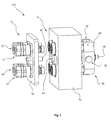
- FIG. 1 further shows a pin 42 which is centered in the connection block 18 between the lines Lx is arranged.
- the pin 42 is between the Sleeve parts 14 a centrally arranged in the connecting block 16 control piston 44 opposite.
- the sleeve parts 14 are also connected to a pressure relief device 70.
- the elements of the pressure relief device 70 are in another Connection block 82 is connected to the connection block 16.
- pressure relief valve systems 50 integrated into the pressure relief device 70 .
- FIG. 1 of the pressure relief valve systems 50, only the outer connections visible.
- Each line Lx is its own pressure relief valve system 50 assigned.
- the existing pressure relief valve systems 50 are not visible in Figure 1 pressure relief chamber 46 connected to a common pressure relief line 48.
- Figure 2 shows the section through a quick coupling 100 in the uncoupled state.
- the plug-in part 12 is connected via the connecting block 18 with the pin 42.
- the male part 12 is in its initial position on the one hand with its housing end face 24 of its housing 22 on an axially displaceable housing element 62 of the sleeve member 14 at.
- a plunger 28 which over a Sealing device 38 seals to the housing 22 of the male part 12, with its End face on a fixedly mounted sliding element 26 at.
- the sliding element 26 is mounted in a sliding element bearing 40.
- the in a plunger bearing 86 axially guided plunger 28 is by the force of a spring element 76 pressed against the sealing device 38 and closes a Chamber 34 against the atmosphere.
- the chamber 34 is in the direction of a medium-leading, pressurized channel 68 through a valve 30 at a Sealing seat 32 closed.
- a pressure relief valve 56 may be arranged in the valve 30, a pressure relief valve 56 may be arranged.
- the inventive Function of the quick coupling 100 as explained the other figures, but is also given without pressure relief valve.
- the sleeve member 14 seals an outer housing 20 against the connection block 16 off. It is arranged opposite the connecting block 16 is not displaced.
- the outer housing 20 is closed on the inner wall, a housing element 21, which forms a stop on a housing block 84 and by means of a sealing device 36 against the housing block 84 of the sleeve part 14 seals.
- the sealing device 36 of the housing element 21 also seals a subsequent further inside housing element 62 against the outside Housing 20 from.
- the housing element 62 is on the inner wall of the housing element 21st arranged.
- Another, axially displaceable housing member 64 is spaced arranged to a housing member 23 in the interior of the sleeve member 14.
- the housing member 62 is between the housing members 62 and 64 as well 21 and 23 axially displaceable against the force of spring elements 58 and 60.
- the spring element 58 and between the housing elements 64 and 23, the spring element 60 is arranged.
- the sliding element 26 seals via a sealing device 88 in uncoupled Condition the sleeve member 14 relative to the axially displaceable housing element 64 off.
- the sliding element 26 is followed by a channel 66, which leads to the medium Line Lx of the coupling part 14 is open.
- the channel 66 is in the Housing block 84 integrated.
- the control piston 44 is located on an axis with the pin 42 and forms in the Bearing sleeve 78 in uncoupled state a stop 80 from.
- the control piston 44 is at the end facing away from the pin via a sealing device with an intermediate storage 90 and a further sealing means with the Pressure relief device 70 connected.
- the control piston 44 engages in uncoupled Condition with a controller 10 in the pressure relief valve system 50 not one.
- the control device 10 comprises the control piston 44 and at least one the control piston 44 arranged cam 54 in the uncoupled state does not engage in the pressure relief valve system 50.
- the pressure relief valve system 50 includes a valve spring 72 and a Valve ball 74.
- the valve ball 74 is disposed radially on the control piston 44.
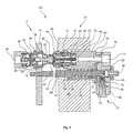
- Figure 3 shows a section through the quick coupling 100 in a first Coupling step.
- the sleeve member 14 is at Coupling process pressure relieved.
- the function of the pressure relief is in Described in more detail below.
- only the reference symbols are discussed, which are needed to explain the function.
- the further reference numerals correspond to the figures 1 and 2.
- the starting position is the uncoupled quick coupling 100 of FIG. 2.
- the connecting block 18 with integrated plug-in part 12 and pin 42 By axial displacement of the connecting block 18 with integrated plug-in part 12 and pin 42 in the direction of the sleeve member 14, the housing 22 with the Housing end face 24 is inserted into the sleeve part 14.
- the spool 44 becomes wider than the initial position in the pressure relief device 70 moved into it.
- the cam 54 runs on the valve ball 74 on.
- the valve ball 74 is against the action of the valve spring 72 an opening between pressure relief connection 52 and pressure relief chamber 46 free.
- the pressure relief acts via the pressure relief connection 52 via the Channel 66 to the chamber 34 in the male part 12 away.
- the control piston 44 leaves by this displacement his stop 80 in the bearing sleeve 78th
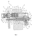
- FIG. 4 shows the section through the quick coupling 100 in the coupled state after the first coupling step.
- the sealing device 88 by axial displacement of the Housing elements 62 and 64 released and a connection to the chamber 34th is available.
- the spring element 76 of the male part 12 is already in partially tensioned state.
- the pressure relief valve system 50 is open and pressure equalization via channel 66 and pressure relief connection 52 occurred.
- FIG. 4 shows that the cam 54 continues to be in the area of the valve ball 74 is arranged.
- a particular embodiment, but not essential to the invention is enabled by a pressure relief valve 56 in one of the two coupling parts 12 or 14 a first pressure relief.
- the plunger 28 touches with its valve 30 side facing a in the Valve 30 integrated pressure pin, which has a pilot flow in existing Gaps in the valve 30 releases.
- Such a device is already known and serves at this point only the description and completion of the function the quick coupling 100.
- the first pressure equalization between the chamber 34 and the channel 68 causes the valve 30 is still at the sealing seat 32 at.
- valve 30 is in the direction of the channel 68 axially displaced by the action of the plunger 28 further.
- the sealing seat 32 is released and via the chamber 34, the channel 68 through the Drukkentlastungs adopted 70 pressure relieved.
- Figure 4 also shows that the pin the control piston 44 at the same time in displaces the pressure relief device 70.
- the end of the cam 54 is reached.
- the cam begins to drain from the valve ball 74. With the drain the cam 54 from the valve ball 74 closes the pressure relief valve system 50 and as a result, the pressure relief chamber 46 is closed.
- This pressure relief function is characterized by the radial arrangement of a plurality of pressure relief valve systems 50 and associated radial pressure relief connections 52 around the pressure relief chamber 46 for any number of clutch pairs 12 and 14 feasible. Other non-radial arrangements are conceivable.
- control device 10 acts equally via the pressure relief valve system 50 and the pressure relief connections on several pairs of couplings 12 and 14 depressurizing.
- Figure 5 shows the quick coupling 100 in fully open coupled Status.
- the spring element 76 visible in the fully tensioned state.
- the pestle 28 presses against the valve 30 and the housing 22 of the male member 12 and is completely shifted in the direction of the sleeve member 14.
- the housing end face 24 has pressed the housing elements 62 against the spring elements 58 and 60, so that the sealing device 88 of the sliding element 26, the connection between Chamber 34 and channel 66 completely releases.
- the control piston 44 is further through the pin 42 in the pressure relief device 70 guided so that the cam 54 leaves the valve ball 74 and the effect on the valve body is canceled.
- the valve ball closes under the action of the spring 72.
- the pressure relief function of the pressure relief device 70 is interrupted. In the quick coupling 100 builds the full medium pressure of the associated open coupling parts 12 and 14 on.
- the male part 12 together with the sleeve part 14 relative to the outer non-displaceable housing 20 of the sleeve member 14 within the connection block 16 postponed.
- the entire plug-in part 12 shifts and the sleeve member 14 guided by the housing member 21 in the outer housing 20th together with the housing block 84.
- the housing block 84 with the bearing sleeve 78 via the intermediate bearing 90 shifts at the same time the entire connection block 82 with the integrated pressure relief device 70 around the same distance.
- the quick coupling 100 has it reached their coupled end position.
- FIG. 6 shows an external view of the quick coupling 100 in the coupled state. Visible are the coupled lines L1 and L2 between the connection blocks 16 and 18 and the pressure relief device 70 accommodating, Connection block 82. Lines L3 and L4 are not visible behind the lines L1 and L2.
- the pressure relief device 70 is not visible from the outside Pressure relief chamber 46 on the common pressure relief line 48th guided. Only indicated by their closure elements are the radial to control piston 44 arranged pressure relief valve systems 50, the coupling process opened and closed via the pin 42 and the control piston 44 become. Furthermore, the outer housing 20 of the male part 12 is visible. The housing block 84 completes between the connection blocks 16 and 82 the figure 6.
- the opening of the quick coupling 100 takes place in the reverse manner.
- the chamber is first 34 opposite the channel 68 by means of the valve 30 under Pressure relief by the pressure relief device 70 is closed.
- the force of the spring element 76 leads to a return of the plunger 28 in the initial state.
- the housing elements 62 and 64 are also under shifting the force of spring elements 58 and 60 back to their original position, so that the sealing device 88 of the sliding element 26 again on the Housing member 64 seals.
- the pressure relief device 70 closes by the control device 10 the area of the valve ball 74 in the pressure relief device 70 leaves and the pressure equalization is interrupted.
- Each coupling part 12 and 14 per se is thus after separation of the connecting blocks 16 and 18 both to the pressure relief connection 52nd sealed as well as frontally.
Landscapes
- Engineering & Computer Science (AREA)
- General Engineering & Computer Science (AREA)
- Mechanical Engineering (AREA)
- Quick-Acting Or Multi-Walled Pipe Joints (AREA)
- Safety Valves (AREA)
- Containers And Packaging Bodies Having A Special Means To Remove Contents (AREA)
- Compositions Of Oxide Ceramics (AREA)
- Media Introduction/Drainage Providing Device (AREA)
Description
- Figur 1
- in einer Außenansicht eine Schnellkupplung im ungekuppelten Zustand;
- Figur 2
- in einem Schnitt die Schnellkupplung im ungekuppelten Zustand;
- Figur 3
- in einem Schnitt die Schnellkupplung im teilweise gekuppelten Zustand in einem ersten Kupplungsschritt;
- Figur 4
- in einem Schnitt die Schnellkupplung im teilweise gekuppelten Zustand in einem zweiten Kupplungsschritt;
- Figur 5
- in einem Schnitt die Schnellkupplung im gekuppelten Zustand und
- Figur 6
- in einer Außenansicht eine Schnellkupplung im gekuppelten Zustand.
- 100
- Schnellkupplung
- 10
- Steuereinrichtung
- 12
- Steckteil
- 14
- Hülsenteil
- 16
- Verbindungsblock
- 18
- Verbindungsblock
- 20
- äußeres Gehäuse
- 21
- Gehäuseelement
- 22
- Gehäuse
- 23
- Gehäuseelement
- 24
- Gehäusestirnfläche
- 26
- Schiebeelement
- 28
- Stößel
- 30
- Ventil
- 32
- Dichtsitz
- 34
- Kammer
- 36
- Dichteinrichtung
- 38
- Dichteinrichtung
- 40
- Schiebeelementlager
- 42
- Betätigungseinrichtung (Zapfen)
- 44
- Steuerkolben
- 46
- Druckentlastungskammer
- 48
- Druckentlastungsleitung
- 50
- Druckentlastungsventilsystem
- 52
- Druckentlastungsverbindung
- 54
- Nocke
- 56
- Druckentlastungsventil
- 58
- Federelement
- 60
- Federelement
- 62
- Gehäuseelement
- 64
- Gehäuseelement
- 66
- Kanal
- 68
- Kanal
- 70
- Druckentlastungseinrichtung
- 72
- Ventilfeder
- 74
- Ventilkugel
- 76
- Federelement
- 78
- Lagerhülse
- 80
- Anschlag
- 82
- Verbindungsblock
- 84
- Gehäuseblock
- 86
- Stößellager
- 88
- Dichteinrichtung
- 90
- Zwischenlager
- 91
- Dichteinrichtung
- Lx
- Leitungen
Claims (20)
- Kupplung (100) zum Verbinden von wenigstens zwei unter Druck stehenden Leitungen (Lx) mit einem ersten Kupplungsteil, das druckdicht mit einem zweiten Kupplungsteil verbindbar ist und mit einer der Kupplung (100) zugeordneten externen Druckentlastungseinrichtung (70), die über wenigstens eine Druckentlastungsverbindung (52) mit wenigstens einer der unter Druck stehenden Leitungen (Lx) verbindbar ist, dadurch gekennzeichnet, dass die Kupplung (100) eine Schnellkupplung ist und dass das erste Kupplungsteil ein Steckteil (12) und gemeinsam mit einer Betätigungseinrichtung (42) für die Druckentlastungseinrichtung (70) in einem Verbindungsblock (18) angeordnet ist.
- Schnellkupplung nach Anspruch 1, dadurch gekennzeichnet, dass das zweite Kupplungsteil ein Hülsenteil (14) ist und gemeinsam mit einer Steuereinrichtung (10) für die Druckentlastungseinrichtung (70) in einem Verbindungsblock (16) angeordnet ist.
- Schnellkupplung nach Anspruch 2, dadurch gekennzeichnet, dass die Steuereinrichtung (10) einen verlagerbaren Steuerkolben (44) mit mindestens einer Nocke (54) umfasst.
- Schnellkupplung nach einem der vorhergehenden Ansprüche, dadurch gekennzeichnet, dass eine Betätigungseinrichtung für die Druckentlastungseinrichtung (70) einen Zapfen (42) umfasst, mit dem der Steuerkolben (44) zusammenwirkt, und insbesondere auf einer Achse mit dem Steuerkolben (44) angeordnet ist.
- Schnellkupplung nach Anspruch 3, dadurch gekennzeichnet, dass die Steuereinrichtung (10) in die Druckentlastungseinrichtung (70) eingreift, die gemeinsam mit einem Teilbereich des Hülsenteiles (14) in einem Verbindungsblock (82) angeordnet ist.
- Schnellkupplung nach einem der vorhergehenden Ansprüche, dadurch gekennzeichnet, dass die Druckentlastungseinrichtung (70) die Steuereinrichtung (10), die Druckentlastungsverbindung (52), mindestens ein Druckentlastungsventilsystem (50), mindestens eine Druckentlastungskammer (46) und mindestens eine Druckentlastungsleitung (48) umfasst.
- Schnellkupplung nach einem der vorhergehenden Ansprüche, dadurch gekennzeichnet, dass das mindestens eine Druckentlastungsventilsystem (50) mindestens eine Ventilfeder (72) und mindestens eine Ventilkugel (74) umfasst.
- Schnellkupplung nach einem der vorhergehenden Ansprüche, dadurch gekennzeichnet, dass jeder Druckentlastungsverbindung (52) mindestens ein Druckentlastungsventilsystem (50) zugeordnet ist.
- Schnellkupplung nach einem der vorhergehenden Ansprüche, dadurch gekennzeichnet, dass mehrere Druckentlastungsventilsysteme (50) der Druckentlastungseinrichtung (70) auf mindestens eine Druckentlastungskammer (46) und mindestens eine Druckentlastungsleitung (48) geführt sind.
- Schnellkupplung nach einem der vorhergehenden Ansprüche, dadurch gekennzeichnet, dass das Druckentlastungsventilsystem (50) radial zum Steuerkolben (44) angeordnet sind.
- Schnellkupplung nach einem der vorhergehenden Ansprüche, dadurch gekennzeichnet, dass die Steuereinrichtung (10) und die Druckentlastungskammer (46) mit ihrer Druckentlastungsleitung (48) auf einer Achse angeordnet sind.
- Schnellkupplung nach einem der vorhergehenden Ansprüche, dadurch gekennzeichnet, dass das Steckteil (12) ein Ventil (30) zwischen einem Kanal (68) und einer Kammer (34) und eine Dichteinrichtung (91) zwischen einem Stößel (28) und einem Gehäuse (22) aufweist.
- Schnellkupplung nach einem der vorhergehenden Ansprüche, dadurch gekennzeichnet, dass das Hülsenteil (14) eine Dichteinrichtung (38) zwischen einem Schiebeelement (26) und einem Gehäuseelement (64) aufweist.
- Schnellkupplung nach einem der vorhergehenden Ansprüche, dadurch gekennzeichnet, dass bei einem Kupplungsvorgang der Kupplungsteile (12) und (14) gleichzeitig die Verbindungsblöcke (16) und (18) gegeneinander verlagerbar sind.
- Schnellkupplung nach einem der vorhergehenden Ansprüche, dadurch gekennzeichnet, dass der Zapfen (42), der den Steuerkolben (44) betätigt, in einem ersten Kupplungsschritt einen Durchgang vom Kanal (66) im Hülsenteil (14) öffnet, wobei über die Nocke (54) des Steuerkolbens (44) das Druckentlastungsventil (56) zur Druckentlastungskammer (46) geöffnet wird.
- Schnellkupplung nach einem der vorhergehenden Ansprüche, dadurch gekennzeichnet, dass das Ventil (30) in einem zweiten Kupplungsschritt eine Verbindung zwischen dem Kanal (68) und der Druckentlastungskammer (46) über das Druckentlastungsventil (56), über die Kammer (34), an der Dichtungseinrichtung (88) vorbei durch den Kanal (66), über die Druckentlastungsverbindung (52) durch das Druckentlastungsventilsystem (50) aufweist, wobei über die Nocke (54) des Steuerkolbens (44) das Druckentlastungsventilsystem (50) zur Druckentlastungskammer (46) und zur anschließenden Druckentlastungsleitung (48) zur Erzeugung eines Druckausgleichs innerhalb der Schnellkupplung (100) geöffnet gehalten wird.
- Schnellkupplung nach einem der vorhergehenden Ansprüche, dadurch gekennzeichnet, dass der Zapfen (42) den Steuerkolben (44) in einem dritten Kupplungsschritt axial verlagert und unter gleichzeitiger Freigabe des Ventils (30) die Kammer (34) und den Kanal (68) miteinander verbindet, wobei die Nocke (54) des Steuerkolbens (44) das Druckentlastungsventilsystem (50) geöffnet hält und die Druckentlastungsverbindung (52) zur Druckentlastungskammer (46) und zur anschließenden Druckentlastungsleitung (48) zur Erzeugung eines Druckausgleichs innerhalb der Schnellkupplung (100) freigibt.
- Schnellkupplung nach einem der vorhergehenden Ansprüche, dadurch gekennzeichnet, dass in einem vierten Kupplungsschritt durch eine weitere axiale Verlagerung des Zapfens (42) der Steuerkolben (44) vollständig in das Druckentlastungsventilsystem (50) eingeführt wird, wobei die Nocke (54) des Steuerkolbens (44) am Druckentlastungsventilsystem (50) vorbeigeführt wird und die Druckentlastungsverbindung (52) zur Druckentlastungskammer (46) und zur anschließenden Druckentlastungsleitung (48) in der Schnellkupplung (100) schließt.
- Schnellkupplung nach Anspruch 18, dadurch gekennzeichnet, dass die Nocke (54) die Ventilkugel (74) freigibt und dadurch das Druckentlastungsventilsystem (50) unter Wirkung der Ventilfeder (72) in die Schließstellung führt.
- Schnellkupplung nach Anspruch 16, dadurch gekennzeichnet, dass in dem zweiten Kupplungsschritt das Druckentlastungsventil (56) durch Betätigung eines Druckstiftes mittels des Stößels (28) in das Ventil (30) öffenbar ist.
Applications Claiming Priority (2)
| Application Number | Priority Date | Filing Date | Title |
|---|---|---|---|
| DE10217922 | 2002-04-22 | ||
| DE10217922A DE10217922B4 (de) | 2002-04-22 | 2002-04-22 | Schnellkupplung |
Publications (3)
| Publication Number | Publication Date |
|---|---|
| EP1357325A2 EP1357325A2 (de) | 2003-10-29 |
| EP1357325A3 EP1357325A3 (de) | 2004-01-02 |
| EP1357325B1 true EP1357325B1 (de) | 2005-06-29 |
Family
ID=28685235
Family Applications (1)
| Application Number | Title | Priority Date | Filing Date |
|---|---|---|---|
| EP03007627A Expired - Lifetime EP1357325B1 (de) | 2002-04-22 | 2003-04-02 | Schnellkupplung |
Country Status (4)
| Country | Link |
|---|---|
| US (1) | US6860290B2 (de) |
| EP (1) | EP1357325B1 (de) |
| AT (1) | ATE298860T1 (de) |
| DE (2) | DE10217922B4 (de) |
Families Citing this family (29)
| Publication number | Priority date | Publication date | Assignee | Title |
|---|---|---|---|---|
| DE10317340A1 (de) * | 2003-04-15 | 2004-11-04 | Ssa System-Spann Ag | Hochdruckkupplung für die Mediendurchführung an Schnellwechselsystemen |
| US7198060B2 (en) * | 2004-05-05 | 2007-04-03 | Parker-Hannifin Corporation | Pressure relieving coupler manifold with internal velocity fuse |
| DE102004055001A1 (de) * | 2004-11-15 | 2006-05-18 | Tema Marketing Ag | Schnellkupplung |
| SE530620C2 (sv) * | 2006-12-01 | 2008-07-22 | Nordhydraulic Ab | Parkeringsorgan för hydraulisk koppling |
| SE530621C2 (sv) * | 2006-12-01 | 2008-07-22 | Nordhydraulic Ab | Hydraulisk anslutning |
| US7909064B2 (en) * | 2007-08-10 | 2011-03-22 | Emerson Process Management Power & Water Solutions, Inc. | Hydraulic isolating manifold |
| JP5051905B2 (ja) * | 2008-02-18 | 2012-10-17 | パスカルエンジニアリング株式会社 | 流体通路接続装置 |
| US8424920B2 (en) * | 2008-03-07 | 2013-04-23 | The Gates Corporation | Multi-port fluid connectors, systems and methods |
| US8191575B2 (en) * | 2008-04-11 | 2012-06-05 | International Business Machines Corporation | Double poppet quick connect |
| CN102256741A (zh) * | 2008-12-17 | 2011-11-23 | 克斯美库股份有限公司 | 带液力耦合器的紧固系统 |
| EP2330331B1 (de) * | 2009-12-04 | 2018-09-26 | Caterpillar Work Tools B. V. | Kopplungsvorrichtung für Verbinderkomponenten |
| TWI415559B (zh) * | 2010-11-23 | 2013-11-11 | Inventec Corp | 可調式冷卻液快速接頭 |
| TWI411758B (zh) * | 2010-11-23 | 2013-10-11 | Inventec Corp | 快速接頭 |
| US8608207B2 (en) * | 2011-11-30 | 2013-12-17 | International Business Machines Corporation | Apparatus to make up multiple quick connect couplings |
| FR2986310B1 (fr) * | 2012-01-31 | 2014-03-21 | Staubli Sa Ets | Systeme de refroidissement avec conduit de circulation de fluide caloporteur |
| PH12013000162B1 (en) | 2012-06-08 | 2021-04-07 | Emerson process man power and water solutions inc | Electronically controllable and testable turbine trip system with redundant bleed manifolds |
| EP2682661A1 (de) | 2012-07-03 | 2014-01-08 | Bayer CropScience AG | Vorrichtung zur kontaminationsfreien Befüllung eines Tanks aus einem Kanister |
| CN104100788B (zh) * | 2013-04-08 | 2016-08-24 | 富泰华工业(深圳)有限公司 | 接头 |
| ITMI20131045A1 (it) * | 2013-06-24 | 2014-12-25 | Faster Spa | Dispositivo multi innesto con sistema automatico di scarico della pressione. |
| EP2884146B8 (de) * | 2013-12-10 | 2017-04-19 | Faster S.p.A. | Mehrfachverbindervorrichtung für die Mehrfachschnellverbindung von mehreren hydraulischen, elektrischen und/oder pneumatischen Leitungen mit der Möglichkeit einzelner manueller Verbinder |
| US9351428B2 (en) * | 2014-08-29 | 2016-05-24 | Lenovo Enterprise Solutions (Singapore) Pte. Ltd. | Blind docking apparatus to enable liquid cooling in compute nodes |
| GB201502980D0 (en) * | 2015-02-23 | 2015-04-08 | Knorr Bremse Systeme | Brake valve arrangement |
| US20180313495A1 (en) * | 2015-12-01 | 2018-11-01 | SKR Industries, LLC | Grease gun coupler with integrated pressure relief valve |
| FR3080165B1 (fr) * | 2018-04-12 | 2020-05-01 | Staubli Faverges | Element de raccord et raccord comprenant un tel element de raccord |
| US20220034436A1 (en) * | 2019-01-15 | 2022-02-03 | Parker-Hannifin Corporation | Multi-coupler manifold with manual and automatic pressure relief |
| DE102020006487A1 (de) | 2020-10-20 | 2022-04-21 | Dürr Somac GmbH | Schnellwechseleinrichtung für einen Fülladapter |
| US20220266601A1 (en) * | 2021-02-22 | 2022-08-25 | Kyocera Document Solutions Inc. | Head unit, recording head, and inkjet recording apparatus therewith |
| US20230003324A1 (en) * | 2021-07-01 | 2023-01-05 | Wilmarc Holdings, Llc | Genderless Aseptic Connector |
| TWM623783U (zh) * | 2021-11-12 | 2022-02-21 | 志合訊息股份有限公司 | 給水裝置及其水管接頭結構 |
Family Cites Families (9)
| Publication number | Priority date | Publication date | Assignee | Title |
|---|---|---|---|---|
| US3544063A (en) * | 1967-10-31 | 1970-12-01 | Percy Barlow | Hydraulic hose coupling connect and disconnect devices |
| SE335653B (de) * | 1969-12-23 | 1971-06-01 | Tico Ab | |
| US3730221A (en) * | 1971-07-09 | 1973-05-01 | Dempco | Hydraulic coupler with pressure relief mechanism |
| US4371004A (en) * | 1980-09-17 | 1983-02-01 | Sysolin Petr V | Automatic coupling device to connect tractor and tractor-drawn means hydraulic systems |
| SE468403B (sv) * | 1990-01-17 | 1993-01-11 | Dart Engineering Ag | Anordning vid kopplingsdel som innefattar tryckreduceringsorgan |
| ATE130919T1 (de) | 1991-07-09 | 1995-12-15 | Faster Srl | Schnellkupplung zum jeweils gleichzeitigen herstellen oder lösen der verbindungen mehrerer kupplungen und/oder anschlussstecker, insbesondere kupplungsblock für anbaufrontlader an fahrzeugen. |
| DE4222218C2 (de) | 1992-07-07 | 1995-11-16 | S & G Implants Gmbh | Pfanne für eine Hüftgelenk-Endoprothese |
| US5464042A (en) * | 1994-04-29 | 1995-11-07 | Aeroquip Corporation | Quick connect air-conditioning coupling |
| DE19938876C2 (de) * | 1999-08-17 | 2002-07-11 | Voswinkel Kg | Anordnung zur Schnellkupplung von Hydrauliksystemen |
-
2002
- 2002-04-22 DE DE10217922A patent/DE10217922B4/de not_active Expired - Lifetime
-
2003
- 2003-04-02 AT AT03007627T patent/ATE298860T1/de not_active IP Right Cessation
- 2003-04-02 EP EP03007627A patent/EP1357325B1/de not_active Expired - Lifetime
- 2003-04-02 DE DE50300690T patent/DE50300690D1/de not_active Expired - Lifetime
- 2003-04-17 US US10/418,426 patent/US6860290B2/en not_active Expired - Fee Related
Also Published As
| Publication number | Publication date |
|---|---|
| EP1357325A3 (de) | 2004-01-02 |
| DE10217922B4 (de) | 2011-02-24 |
| US6860290B2 (en) | 2005-03-01 |
| ATE298860T1 (de) | 2005-07-15 |
| DE10217922A1 (de) | 2003-11-06 |
| EP1357325A2 (de) | 2003-10-29 |
| US20030201017A1 (en) | 2003-10-30 |
| DE50300690D1 (de) | 2005-08-04 |
Similar Documents
| Publication | Publication Date | Title |
|---|---|---|
| DE10217922B4 (de) | Schnellkupplung | |
| EP0381069B1 (de) | Kupplungsmuffe für hydraulische Leitungsverbindung | |
| EP1657481B1 (de) | Schnellkupplung | |
| EP0100090B1 (de) | Druckluftkupplung | |
| DE3131095C2 (de) | ||
| EP2909519B1 (de) | Koaxiale hochdruckkupplung mit ueberdruckentlastung | |
| EP0038056A2 (de) | Schnellkupplung für Schläuche o.dgl. | |
| DE69807179T2 (de) | Unter Druck zusammensteckbare Schnellverbindungskupplung | |
| DE4101001A1 (de) | Kupplungsteilvorrichtung mit druckreduzierelementen | |
| EP0191384B1 (de) | Ventilzusammenbau | |
| DE1924213A1 (de) | Kompressor-Zylinder-Entlastungsvorrichtung | |
| EP0278420A1 (de) | Schnellverschlusskupplung für insbesondere Hydraulikleitungen | |
| DE2623934C3 (de) | Steckkupplung zum Verbinden von Gasleitungen | |
| EP1440225A2 (de) | Hydraulik actuator for an engine valve | |
| DE2926539C2 (de) | Regelventil für Fahrzeugbremsanlagen mit zwei Bremskreisen | |
| EP0621430B1 (de) | Hydraulik-Steckkupplung | |
| DE4129755C2 (de) | Doppelsitz-Ventilanordnung | |
| DE4338665A1 (de) | Hydraulik-Steckkupplung | |
| DE19854453A1 (de) | Anlaufsteuerung zum Ansteuern einer hydraulischen Kolben-Zylinder-Einheit | |
| DE2909504A1 (de) | Magnetventil | |
| DE2118207C3 (de) | Preßform mit mehreren, gleitbeweglich in einem Gehäuse angeordneten Matrizen | |
| EP1707863B9 (de) | Kupplungsteil einer Druckmittel-Steckkupplung | |
| DE102020113290A1 (de) | Ventil mit einem Rückflussverhinderer | |
| DE2164606C3 (de) | Hauptzylinder für Zweikreis-Bremsanlagen | |
| DE3713284C2 (de) |
Legal Events
| Date | Code | Title | Description |
|---|---|---|---|
| PUAI | Public reference made under article 153(3) epc to a published international application that has entered the european phase |
Free format text: ORIGINAL CODE: 0009012 |
|
| AK | Designated contracting states |
Kind code of ref document: A2 Designated state(s): AT BE BG CH CY CZ DE DK EE ES FI FR GB GR HU IE IT LI LU MC NL PT RO SE SI SK TR |
|
| AX | Request for extension of the european patent |
Extension state: AL LT LV MK |
|
| PUAL | Search report despatched |
Free format text: ORIGINAL CODE: 0009013 |
|
| AK | Designated contracting states |
Kind code of ref document: A3 Designated state(s): AT BE BG CH CY CZ DE DK EE ES FI FR GB GR HU IE IT LI LU MC NL PT RO SE SI SK TR |
|
| AX | Request for extension of the european patent |
Extension state: AL LT LV MK |
|
| 17P | Request for examination filed |
Effective date: 20040211 |
|
| 17Q | First examination report despatched |
Effective date: 20040430 |
|
| AKX | Designation fees paid |
Designated state(s): AT BE BG CH CY CZ DE DK EE ES FI FR GB GR HU IE IT LI LU MC NL PT RO SE SI SK TR |
|
| GRAP | Despatch of communication of intention to grant a patent |
Free format text: ORIGINAL CODE: EPIDOSNIGR1 |
|
| RAP1 | Party data changed (applicant data changed or rights of an application transferred) |
Owner name: TEMA MARKETING AG |
|
| GRAS | Grant fee paid |
Free format text: ORIGINAL CODE: EPIDOSNIGR3 |
|
| GRAA | (expected) grant |
Free format text: ORIGINAL CODE: 0009210 |
|
| AK | Designated contracting states |
Kind code of ref document: B1 Designated state(s): AT BE BG CH CY CZ DE DK EE ES FI FR GB GR HU IE IT LI LU MC NL PT RO SE SI SK TR |
|
| PG25 | Lapsed in a contracting state [announced via postgrant information from national office to epo] |
Ref country code: SK Free format text: LAPSE BECAUSE OF FAILURE TO SUBMIT A TRANSLATION OF THE DESCRIPTION OR TO PAY THE FEE WITHIN THE PRESCRIBED TIME-LIMIT Effective date: 20050629 Ref country code: IE Free format text: LAPSE BECAUSE OF FAILURE TO SUBMIT A TRANSLATION OF THE DESCRIPTION OR TO PAY THE FEE WITHIN THE PRESCRIBED TIME-LIMIT Effective date: 20050629 Ref country code: CZ Free format text: LAPSE BECAUSE OF FAILURE TO SUBMIT A TRANSLATION OF THE DESCRIPTION OR TO PAY THE FEE WITHIN THE PRESCRIBED TIME-LIMIT Effective date: 20050629 Ref country code: FI Free format text: LAPSE BECAUSE OF FAILURE TO SUBMIT A TRANSLATION OF THE DESCRIPTION OR TO PAY THE FEE WITHIN THE PRESCRIBED TIME-LIMIT Effective date: 20050629 Ref country code: SI Free format text: LAPSE BECAUSE OF FAILURE TO SUBMIT A TRANSLATION OF THE DESCRIPTION OR TO PAY THE FEE WITHIN THE PRESCRIBED TIME-LIMIT Effective date: 20050629 Ref country code: RO Free format text: LAPSE BECAUSE OF FAILURE TO SUBMIT A TRANSLATION OF THE DESCRIPTION OR TO PAY THE FEE WITHIN THE PRESCRIBED TIME-LIMIT Effective date: 20050629 Ref country code: NL Free format text: LAPSE BECAUSE OF FAILURE TO SUBMIT A TRANSLATION OF THE DESCRIPTION OR TO PAY THE FEE WITHIN THE PRESCRIBED TIME-LIMIT Effective date: 20050629 |
|
| REG | Reference to a national code |
Ref country code: GB Ref legal event code: FG4D Free format text: NOT ENGLISH |
|
| REG | Reference to a national code |
Ref country code: CH Ref legal event code: EP |
|
| GBT | Gb: translation of ep patent filed (gb section 77(6)(a)/1977) |
Effective date: 20050629 |
|
| REF | Corresponds to: |
Ref document number: 50300690 Country of ref document: DE Date of ref document: 20050804 Kind code of ref document: P |
|
| REG | Reference to a national code |
Ref country code: IE Ref legal event code: FG4D Free format text: LANGUAGE OF EP DOCUMENT: GERMAN |
|
| PG25 | Lapsed in a contracting state [announced via postgrant information from national office to epo] |
Ref country code: BG Free format text: LAPSE BECAUSE OF FAILURE TO SUBMIT A TRANSLATION OF THE DESCRIPTION OR TO PAY THE FEE WITHIN THE PRESCRIBED TIME-LIMIT Effective date: 20050929 Ref country code: GR Free format text: LAPSE BECAUSE OF FAILURE TO SUBMIT A TRANSLATION OF THE DESCRIPTION OR TO PAY THE FEE WITHIN THE PRESCRIBED TIME-LIMIT Effective date: 20050929 Ref country code: DK Free format text: LAPSE BECAUSE OF FAILURE TO SUBMIT A TRANSLATION OF THE DESCRIPTION OR TO PAY THE FEE WITHIN THE PRESCRIBED TIME-LIMIT Effective date: 20050929 |
|
| REG | Reference to a national code |
Ref country code: SE Ref legal event code: TRGR |
|
| NLV1 | Nl: lapsed or annulled due to failure to fulfill the requirements of art. 29p and 29m of the patents act | ||
| PG25 | Lapsed in a contracting state [announced via postgrant information from national office to epo] |
Ref country code: PT Free format text: LAPSE BECAUSE OF FAILURE TO SUBMIT A TRANSLATION OF THE DESCRIPTION OR TO PAY THE FEE WITHIN THE PRESCRIBED TIME-LIMIT Effective date: 20051207 |
|
| PG25 | Lapsed in a contracting state [announced via postgrant information from national office to epo] |
Ref country code: HU Free format text: LAPSE BECAUSE OF FAILURE TO SUBMIT A TRANSLATION OF THE DESCRIPTION OR TO PAY THE FEE WITHIN THE PRESCRIBED TIME-LIMIT Effective date: 20051230 |
|
| REG | Reference to a national code |
Ref country code: IE Ref legal event code: FD4D |
|
| PG25 | Lapsed in a contracting state [announced via postgrant information from national office to epo] |
Ref country code: AT Free format text: LAPSE BECAUSE OF NON-PAYMENT OF DUE FEES Effective date: 20060402 |
|
| ET | Fr: translation filed | ||
| PG25 | Lapsed in a contracting state [announced via postgrant information from national office to epo] |
Ref country code: MC Free format text: LAPSE BECAUSE OF NON-PAYMENT OF DUE FEES Effective date: 20060430 Ref country code: BE Free format text: LAPSE BECAUSE OF NON-PAYMENT OF DUE FEES Effective date: 20060430 |
|
| PLBE | No opposition filed within time limit |
Free format text: ORIGINAL CODE: 0009261 |
|
| STAA | Information on the status of an ep patent application or granted ep patent |
Free format text: STATUS: NO OPPOSITION FILED WITHIN TIME LIMIT |
|
| 26N | No opposition filed |
Effective date: 20060330 |
|
| REG | Reference to a national code |
Ref country code: CH Ref legal event code: PL |
|
| BERE | Be: lapsed |
Owner name: TEMA MARKETING A.G. Effective date: 20060430 |
|
| PG25 | Lapsed in a contracting state [announced via postgrant information from national office to epo] |
Ref country code: LI Free format text: LAPSE BECAUSE OF NON-PAYMENT OF DUE FEES Effective date: 20070430 Ref country code: CH Free format text: LAPSE BECAUSE OF NON-PAYMENT OF DUE FEES Effective date: 20070430 |
|
| PG25 | Lapsed in a contracting state [announced via postgrant information from national office to epo] |
Ref country code: EE Free format text: LAPSE BECAUSE OF FAILURE TO SUBMIT A TRANSLATION OF THE DESCRIPTION OR TO PAY THE FEE WITHIN THE PRESCRIBED TIME-LIMIT Effective date: 20050629 |
|
| PG25 | Lapsed in a contracting state [announced via postgrant information from national office to epo] |
Ref country code: LU Free format text: LAPSE BECAUSE OF NON-PAYMENT OF DUE FEES Effective date: 20060402 Ref country code: TR Free format text: LAPSE BECAUSE OF FAILURE TO SUBMIT A TRANSLATION OF THE DESCRIPTION OR TO PAY THE FEE WITHIN THE PRESCRIBED TIME-LIMIT Effective date: 20050629 |
|
| PG25 | Lapsed in a contracting state [announced via postgrant information from national office to epo] |
Ref country code: CY Free format text: LAPSE BECAUSE OF FAILURE TO SUBMIT A TRANSLATION OF THE DESCRIPTION OR TO PAY THE FEE WITHIN THE PRESCRIBED TIME-LIMIT Effective date: 20050629 |
|
| PG25 | Lapsed in a contracting state [announced via postgrant information from national office to epo] |
Ref country code: ES Free format text: LAPSE BECAUSE OF NON-PAYMENT OF DUE FEES Effective date: 20060430 |
|
| PGFP | Annual fee paid to national office [announced via postgrant information from national office to epo] |
Ref country code: FR Payment date: 20121128 Year of fee payment: 10 Ref country code: DE Payment date: 20121024 Year of fee payment: 10 |
|
| PGFP | Annual fee paid to national office [announced via postgrant information from national office to epo] |
Ref country code: IT Payment date: 20121030 Year of fee payment: 10 Ref country code: GB Payment date: 20121023 Year of fee payment: 10 Ref country code: SE Payment date: 20121030 Year of fee payment: 10 |
|
| REG | Reference to a national code |
Ref country code: SE Ref legal event code: EUG |
|
| GBPC | Gb: european patent ceased through non-payment of renewal fee |
Effective date: 20130402 |
|
| PG25 | Lapsed in a contracting state [announced via postgrant information from national office to epo] |
Ref country code: SE Free format text: LAPSE BECAUSE OF NON-PAYMENT OF DUE FEES Effective date: 20130403 Ref country code: DE Free format text: LAPSE BECAUSE OF NON-PAYMENT OF DUE FEES Effective date: 20131101 Ref country code: GB Free format text: LAPSE BECAUSE OF NON-PAYMENT OF DUE FEES Effective date: 20130402 |
|
| REG | Reference to a national code |
Ref country code: FR Ref legal event code: ST Effective date: 20131231 |
|
| REG | Reference to a national code |
Ref country code: DE Ref legal event code: R119 Ref document number: 50300690 Country of ref document: DE Effective date: 20131101 |
|
| PG25 | Lapsed in a contracting state [announced via postgrant information from national office to epo] |
Ref country code: FR Free format text: LAPSE BECAUSE OF NON-PAYMENT OF DUE FEES Effective date: 20130430 Ref country code: IT Free format text: LAPSE BECAUSE OF NON-PAYMENT OF DUE FEES Effective date: 20130402 |