EP1357033A2 - Apparatus for strapping goods with a band - Google Patents
Apparatus for strapping goods with a band Download PDFInfo
- Publication number
- EP1357033A2 EP1357033A2 EP03007090A EP03007090A EP1357033A2 EP 1357033 A2 EP1357033 A2 EP 1357033A2 EP 03007090 A EP03007090 A EP 03007090A EP 03007090 A EP03007090 A EP 03007090A EP 1357033 A2 EP1357033 A2 EP 1357033A2
- Authority
- EP
- European Patent Office
- Prior art keywords
- drive
- band
- roller
- belt
- tape
- Prior art date
- Legal status (The legal status is an assumption and is not a legal conclusion. Google has not performed a legal analysis and makes no representation as to the accuracy of the status listed.)
- Withdrawn
Links
Images


Classifications
-
- B—PERFORMING OPERATIONS; TRANSPORTING
- B65—CONVEYING; PACKING; STORING; HANDLING THIN OR FILAMENTARY MATERIAL
- B65B—MACHINES, APPARATUS OR DEVICES FOR, OR METHODS OF, PACKAGING ARTICLES OR MATERIALS; UNPACKING
- B65B13/00—Bundling articles
- B65B13/18—Details of, or auxiliary devices used in, bundling machines or bundling tools
- B65B13/185—Details of tools
- B65B13/187—Motor means
-
- B—PERFORMING OPERATIONS; TRANSPORTING
- B65—CONVEYING; PACKING; STORING; HANDLING THIN OR FILAMENTARY MATERIAL
- B65B—MACHINES, APPARATUS OR DEVICES FOR, OR METHODS OF, PACKAGING ARTICLES OR MATERIALS; UNPACKING
- B65B13/00—Bundling articles
- B65B13/18—Details of, or auxiliary devices used in, bundling machines or bundling tools
- B65B13/22—Means for controlling tension of binding means
Definitions
- the invention relates to a device for Strapping goods with tape, in particular Plastic strap, with a housing with Belt guide channel, one rotatable with the frame supported support roller, one to the support roller pressable by means of a drive Tensioner pulley, a clamping device for that Strap end of the strapping, one Clamping device for the fed tape, one Band connection device and one Strap separator.
- Such a device is, for example, from known from DE 100 26 200 A1.
- the well-known Device is relatively bulky because of that provided eccentric drive, which has a Handlebar lever controlled, held on the base frame is.
- Another disadvantage is that several Freewheels are provided, one with Brake and one as in one direction of rotation locking freewheel is formed. The Arrangement of the freewheels causes additional Material and assembly costs.
- an extreme compact and functional device create that on freewheels with brake or in one-way locking freewheels waived.
- the tension pulley with its drive shaft rotatable eccentrically in one side of the housing stored rotary shaft which is supported by stops fixed to the housing can be rotated to a limited extent and on which the drive or drive including gear is attached and with its output shaft rotatably with the drive shaft of the tension pulley is connected, and that the end face of the Tensioner roller with a friction lining on one backing plate fixed to the housing so that the rotary shaft when starting up the drive including drive or drive-gear unit and together with the drive shaft and idler pulley limited angular degree and the tension pulley is pressed on the support roller, with another same operating mode of the drive located between the tension pulley and the support pulley Band is tensioned and by reversing the Direction of drive the rotary shaft including drive or including drive-gear unit and velvet Drive shaft and idler pulley to a limited Angle degree is turned back and the tension pulley releasing the tape from the support roller is spaced.
- the appropriate tape mainly plastic tape
- the housing provided Tape guide channel are introduced so that it the gap between the support roller and the Tension roller penetrated. That from the device Leaving tape end can, for example, manually to be placed around the corresponding item and with the free end back into the device be introduced, with the free end of the Clamping device for the tape end of the Strapping is clamped. Then you can the drive for the tensioning roller in the tensioning direction be put into operation.
- the chosen arrangement achieves that first the drive or the drive together Gearbox through the fixed stops limited by a certain degree of angle.
- the time offset can be a few tenths of a second be.
- the switch is a delay switch.
- a belt transport drive is provided, the one driven Has transport roller, by means of which the belt can be pressed against the support roller and is transportable.
- the belt transport drive is an additional one Means are provided, the user first the supplied strapping through the Device leads and spends in target position. Then the belt transport drive can be turned on, by means of which the tape pressed against the support roller and on is transported. Depending on the Commissioning time of the belt transport drive can be the length of the belt being transported be determined. The user can then, after the belt transport drive is switched off, the Place the tape around the goods package and the tape end in insert the device to the others Operations for tensioning and welding the band by means of the device.
- the belt conveyor drive the tape is transported safely, regardless of different strip thicknesses and / or regardless of any flattening the support roller, which is usually a Has elastomer covering, it is provided that the Belt transport drive by means of a frame fixed mounted swing arm is pivotally mounted, the rocker arm by means of a spring Direction is pushed onto the support roller, so that the transport roller resilient to the support roller is pressed.
- the length the transported by the belt transport drive Band is adjustable so that the Belt transport drive after passing through the corresponding tape length is switched off.
- the Belt transport drive an electric motor, especially DC motor.
- the Direction of rotation of the belt transport drive Operation of a switch is reversible through the end of the tape around the package Band that in the clamping device for the Band end is inserted, can be actuated.
- the reversal of the belt transport drive can slightly delayed to operate the Switch done through the tape end so that again the risk of pinching or crushing the user is avoided.
- the switch is a Delay switch is.
- the drive of the rotating shaft depending on the Runtime of the reversed belt transport drive can be switched on, or depending on the load electromotive belt transport drive, especially DC shunt motor, at Reaching a certain clamping torque can be switched on by the current increase of the Belt transport drive recorded and from this the Switching process for the drive is derived or with a hydraulic or air motor Drive by means of a Flow pressure relief valve can be switched on is that when a certain one is reached Flow pressure in hydraulics or pneumatics triggers.
- the reversed Belt transport drive first reaches one certain tension of the strapping.
- the acquisition of the load condition will be reached a specific setpoint of the clamping torque determined and by means of an electronic Circuit converted into a signal by means of which the drive of the rotary shaft for actuating the Tensioner is switched.
- the load-dependent Detection can with electromotive Belt transport drives, for example DC shunt motors, thereby that the current increase of the belt transport drive recorded and from this the signals for the Triggering of the switching process can be derived.
- the clamping device for the fed, tensioned belt in the clamped position is switched when the target voltage state (time-dependent or load-dependent) is reached.
- the still free band, which is only with his End is clamped in the device tensioned by means of the tensioning device.
- the Tension which is either time-dependent or again load-dependent can be, the clamping device for the fed tensioned band in the clamped position transferred so that both ends of the Strapping are fixed.
- tape cutting device Band connecting device in particular Welding device is activated.
- a possibly preferred further education is seen in that with the drive coupled gear is a worm gear, whose worm rotates with the output shaft the drive is connected and its Worm gear directed coaxially to the tensioning gear shaft is, the transmission preferably as self-locking worm gear is designed.
- the Spring means is formed by disc springs that in an annular groove in the tension roller end face are inserted, in which the friction lining is inserted.
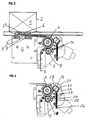
- the Device consists of a generally with 3rd designated housing, which fixed to the frame is supported and which is a tape guide channel in which the tape according to Figure 3 from below can be introduced and by corresponding guide elements again from the Device can be led out (in Figure 3 top left).
- the device comprises one on the frame 3 rotatably supported support roller 4, the preferably an elastomeric friction lining has, and one to the support roller 4th pressable and by means of a later described drive rotatable tension pulley 5th
- the device further comprises a Clamping device 6 for the end of the Goods package 1 laid tensioning strap 2 and one Clamping device 7 for the fed band 2 in Area of the goods package 1.
- the Device a belt cutting device 8, by means of which the fed tape from the incoming Tape can be cut off so that the strapped Item 1 after tensioning the tape can be removed and a Band connecting device, for example Welding device 9, by means of which the ends of the Band, which is placed around the item 1 and around the piece of goods is clamped, connected can.
- a Band connecting device for example Welding device 9
- the tension pulley 5 is with its drive shaft 10 rotatable eccentrically in one side of the housing mounted rotary shaft 11 mounted.
- Rotary shaft 11 is on the back of the device, that is on the back of the tension roller 5 a plate 12 attached to one radially projecting stop 13.
- the housing 3 has two stops 14, 15 on the back, the limit the rotational mobility of the rotating shaft.
- On the plate 12 attached to the rotary shaft 11 is the drive 16 (an electric motor) and the associated transmission 17 attached, so that it follows the rotating movement of the rotating shaft 11.
- the drive 16, 17 is with its output shaft rotatably with the drive shaft 10 of the tension pulley 5 connected.
- the face of the tension pulley 5 is based on a friction lining 18 backing plate 19 fixed to the housing, so that at commissioning of the drive 16.17 in Clamping direction the disc 12 with its stop 13 from the position according to FIG. 6 into the position is adjusted according to Figure 7, what the adjustment from the position according to FIG. 3 into the position corresponds to Figure 4.
- a friction lining 18 and the pressure plate 19 becomes one frictional counter bearing formed which corresponding movement of the disc 12 and the Drive unit 16.17 allows.
- a tape guide wedge 20 is provided, which with the rotary shaft 11th rotates. In the disengaged position of the tension pulley 5 3, this tape guide wedge 20 forms part of the tape guide.
- tension roller 5 located tension roller 5 according to Figure 4 is the Tape guide wedge 20 from the tape guide position in adjusted a position not leading the tape so that the tension roller 5 can be pressed against the support roller 4 is.
- a belt transport drive 21 provided of a driven transport roller 22, by means of which the band 2 against the Support roller 4 can be pressed and transported.
- the belt transport drive 21 is by means of a swing arm 23 mounted on the frame is pivotable supported.
- the pivot bearing is indicated at 24.
- the rocker 23 is biased by means of a Spring (helical tension spring) 25 to the support roller 4 pressed.
- the spring force can be adjusted by the Set screw 26 can be set.
- the belt transport drive 21 is by means of a the control switch, not shown switched on. Furthermore, the length of the Belt transport drive 21 transported belt 2 adjustable so that the belt transport drive 21 after running through the corresponding belt length off.
- the Belt transport drive 21 an electric motor, especially DC motor.
- the Direction of rotation of the belt transport drive 21 is reversible by pressing a switch. At the The transport roller rotates forward 22 in the view according to FIG Clockwise. When reversing the direction of rotation of the Transport drive is the belt 2, which around the goods package 1 is placed, already biased.
- the circuit of the belt transport drive in reverse direction of rotation takes place in that the End of band of the band wrapped around goods package 1 2 is inserted into the clamping device 6 and operated a switch 27 located there is coupled to the belt transport drive 21 in order to operate it in the reverse direction.
- the reversal of the Belt transport drive 21 slightly delayed for actuation of switch 27 respectively.
- the drive 16, 17 of the rotary shaft 10 is in Depends on the runtime of the rerouted Belt transport drive 21 switched or preferably depending on the load Electromotive belt transport drive 21 in that the current rise of the Belt transport drive 21 detected and from this the switching process for switching on the drive 16.17 is derived.
- the clamping device 7 for the supplied tensioned band 2 is in the clamped position switched when the target voltage state is reached.
- the Target voltage state depending on time or are recorded depending on the load, so that the Clamping device either by a Timer or by a Current rise circuit or the like is switched.
- the Tape separator 8 activated and the tape severed. Before that, the tape became relaxed that the drive 16,17 reversing is operated. Then in Disconnecting position of the belt cutting device 8 the connecting device for connecting the Band ends activated, especially the Welding device 9.
- this is with the drive 16 coupled gear 17 a worm gear, whose worm rotates with the output shaft of the drive 16 designed as an electric motor is connected and its worm wheel coaxial with Tensioning wheel shaft 10 is arranged.
- the gear is preferably as a self-locking Worm gear designed.
- the invention provides a device for Available with a compact structure and few extremely susceptible components is functional, being a semi-automatic Strapping of goods 1 is possible.
- the invention is not based on that Embodiment limited, but in the frame Revelation is often variable.
Landscapes
- Engineering & Computer Science (AREA)
- Mechanical Engineering (AREA)
- Basic Packing Technique (AREA)
Abstract
Description
Die Erfindung betrifft eine Vorrichtung zum Umreifen von Warenstücken mit Band, insbesondere Kunststoffband, mit einem Gehäuse mit Bandführungskanal, einer gestellfest drehbar gehalterten Stützrolle, einer an die Stützrolle andrückbaren mittels eines Antriebes drehbaren Spannrolle, einer Klemmeinrichtung für das Bandende des Umreifungsbandes, einer Klemmeinrichtung für das zugeführte Band, einer Bandverbindungseinrichtung sowie einer Bandtrennvorrichtung.The invention relates to a device for Strapping goods with tape, in particular Plastic strap, with a housing with Belt guide channel, one rotatable with the frame supported support roller, one to the support roller pressable by means of a drive Tensioner pulley, a clamping device for that Strap end of the strapping, one Clamping device for the fed tape, one Band connection device and one Strap separator.
Eine derartige Vorrichtung ist beispielsweise aus der DE 100 26 200 A1 bekannt. Die bekannte Vorrichtung ist relativ voluminös wegen des dort vorgesehenen Exzenterantriebes, der über einen Lenkerhebel gesteuert, am Grundrahmen gehaltert ist. Zudem ist dabei nachteilig, dass mehrere Freiläufe vorgesehen sind, von denen einer mit Bremse und einer als in einer Drehrichtung sperrender Freilauf ausgebildet ist. Die Anordnung der Freiläufe verursacht zusätzliche Material- und Montagekosten.Such a device is, for example, from known from DE 100 26 200 A1. The well-known Device is relatively bulky because of that provided eccentric drive, which has a Handlebar lever controlled, held on the base frame is. Another disadvantage is that several Freewheels are provided, one with Brake and one as in one direction of rotation locking freewheel is formed. The Arrangement of the freewheels causes additional Material and assembly costs.
Ausgehend von diesem Stand der Technik liegt der Erfindung die Aufgabe zugrunde, eine äußerst kompakte und funktionstüchtige Vorrichtung zu schaffen, die auf Freiläufe mit Bremse oder in einer Drehrichtung sperrende Freiläufe verzichtet.Based on this state of the art Invention based on the task, an extreme compact and functional device create that on freewheels with brake or in one-way locking freewheels waived.
Zur Lösung dieser Aufgabe wird vorgeschlagen, dass die Spannrolle mit ihrer Antriebswelle drehbar exzentrisch in einer gehäuseseitig gelagerten Drehwelle gelagert ist, welche durch gehäusefeste Anschläge begrenzt drehbar ist und an der der Antrieb oder der Antrieb samt Getriebe befestigt ist und mit seiner Abtriebswelle drehfest mit der Antriebswelle der Spannrolle verbunden ist, und dass die Stirnfläche der Spannrolle sich mit einem Reibbelag an einer gehäusefesten Gegendruckplatte abstützt, so dass bei Inbetriebnahme des Antriebes die Drehwelle samt Antrieb bzw. samt Antriebs-Getriebe-Einheit und samt Antriebswelle und Spannrolle um einen begrenzten Winkelgrad gedreht und die Spannrolle an die Stützrolle angedrückt ist, bei weiterer gleichsinniger Betriebsweise des Antriebes das zwischen Spannrolle und Stützrolle befindliche Band gespannt wird und durch Umkehr der Antriebsrichtung die Drehwelle samt Antrieb bzw. samt Antriebs-Getriebe-Einheit und samt Antriebswelle und Spannrolle, um einen begrenzten Winkelgrad zurückgedreht ist und die Spannrolle von der Stützrolle das Band freigebend beabstandet ist.To solve this task, it is proposed that the tension pulley with its drive shaft rotatable eccentrically in one side of the housing stored rotary shaft which is supported by stops fixed to the housing can be rotated to a limited extent and on which the drive or drive including gear is attached and with its output shaft rotatably with the drive shaft of the tension pulley is connected, and that the end face of the Tensioner roller with a friction lining on one backing plate fixed to the housing so that the rotary shaft when starting up the drive including drive or drive-gear unit and together with the drive shaft and idler pulley limited angular degree and the tension pulley is pressed on the support roller, with another same operating mode of the drive located between the tension pulley and the support pulley Band is tensioned and by reversing the Direction of drive the rotary shaft including drive or including drive-gear unit and velvet Drive shaft and idler pulley to a limited Angle degree is turned back and the tension pulley releasing the tape from the support roller is spaced.
Durch diese Anordnung ist eine äußerst Platz sparende Ausbildung erreicht, wobei auf Freiläufe oder dergleichen Mittel verzichtet wird. Insgesamt werden nur wenige Bauteile verwendet, die nur gering verschleißanfällig sind und daher eine hohe Lebensdauer der Vorrichtung erwarten lassen. This arrangement is an extremely space Saving training achieved, with freewheels or similar means is dispensed with. Overall, only a few components are used, which are only slightly susceptible to wear and therefore expect a long service life of the device to let.
Zur Inbetriebnahme der Vorrichtung kann das entsprechende Band, vornehmlich Kunststoffband, in den gehäuseseitig vorgesehenen Bandführungskanal eingebracht werden, so dass es den Spalt zwischen der Stützrolle und der Spannrolle durchsetzt. Das aus der Vorrichtung austretende Bandende kann beispielsweise manuell um das entsprechende Warenstück gelegt werden und mit dem freien Ende wieder in die Vorrichtung eingeführt werden, wobei das freie Ende von der Klemmeinrichtung für das Bandende des Umreifungsbandes geklemmt wird. Anschließend kann der Antrieb für die Spannrolle in Spannrichtung in Betrieb genommen werden. Hierbei wird durch die gewählte Anordnung erreicht, dass sich zunächst der Antrieb oder der Antrieb samt Getriebe durch die gehäusefesten Anschläge begrenzt um einen bestimmten Winkelgrad dreht. Was auch hierdurch in vorbestimmbarer Weise erreicht wird, dass sich die Stirnfläche der Spannrolle mit dem Reibbelag an der gehäusefesten Gegendruckplatte abstützt, so dass durch diesen Reibschluss ein Gegenlager am Gehäuse erreicht wird, um die Drehbewegung des Antriebes oder des Antriebes samt Getriebe zu erreichen. Hierbei wird gleichzeitig die Spannrolle in die Spannstellung überführt, in der die Spannrolle unter Zwischenlage des durchgeführten Bandes gegen die Stützrolle angepresst wird. Durch die gegebenenfalls einstellbaren gehäuseseitigen Anschläge, durch die die Drehbewegung des Gesamtelementes begrenzt ist, kann eine Einstellung auf die Banddicke des durchgeführten Bandes erfolgen, so dass der gewünschte Wirkeingriff zwischen Spannrolle und Stützrolle erreicht ist. Bei weiterer gleichsinniger Inbetriebnahme des Antriebes wird die Antriebswelle und somit die Spannrolle gedreht und das Band angezogen und gespannt. Es erfolgt dann nach Erreichen des Sollspannungszustandes die Klemmung auch des noch freien Endes des Bandes, so dass das Bandende und das entsprechende Teil des zulaufenden Bandes übereinander liegen und das zulaufende Band abgetrennt und die so gebildeten beiden Bandenden miteinander verschweißt werden können. Unmittelbar nach der Verschweißung oder kurz dazu zeitversetzt öffnen die Klemmen und geben das Band vollständig frei, so dass das Packstück fertig umreift entnommen werden kann. Zusätzlich wird der Antrieb reversierend in Betrieb gesetzt, so dass die Spannrolle wieder von der Stützrolle entfernt wird und ein ausreichender Durchlassspalt für den freien Durchlauf des erneut zugeführten Bandes zur Verfügung gestellt ist.To start up the device, the appropriate tape, mainly plastic tape, in the housing provided Tape guide channel are introduced so that it the gap between the support roller and the Tension roller penetrated. That from the device Leaving tape end can, for example, manually to be placed around the corresponding item and with the free end back into the device be introduced, with the free end of the Clamping device for the tape end of the Strapping is clamped. Then you can the drive for the tensioning roller in the tensioning direction be put into operation. Here is by the chosen arrangement achieves that first the drive or the drive together Gearbox through the fixed stops limited by a certain degree of angle. Which also results in a predeterminable way is achieved that the end face of the Tension roller with the friction lining on the housing-fixed Backing plate supports so that through this Friction has reached a counter bearing on the housing is to the rotational movement of the drive or Achieve drive including gear. in this connection is the tensioning pulley in the Tension position transferred in the tension roller with the interposition of the tape carried out is pressed against the support roller. Through the optionally adjustable housing side Stops by which the rotary movement of the Overall element is limited, can Adjustment to the tape thickness of the performed Tape done so that the desired Active intervention between the tension pulley and the support pulley is reached. In the same direction The drive is put into operation Drive shaft and thus the tension pulley rotated and tightened and tightened the tape. It takes place then after reaching the target voltage state the clamping of the still free end of the Tape so that the tape end and that corresponding part of the incoming band lie on top of each other and the incoming tape separated and the two tape ends thus formed can be welded together. Immediately after welding or shortly afterwards the terminals open with a time delay and give it Band completely free, leaving the package ready strapped can be removed. additionally the drive is put into reverse operation, so that the idler pulley back off the support pulley is removed and sufficient Passage gap for the free passage of the re-fed tape provided is.
Um bei diesem im wesentlichen handbetätigten Umreifungsgerät eine weitere Automatisierung zu erreichen, ist vorgesehen, dass die Inbetriebnahme des Antriebes durch einen Schalter ausgelöst ist, der durch das Bandende des um das Warenpaket gelegten Bandes, das in die Klemmeinrichtung für das Bandende eingeführt ist, betätigt ist.In order for this essentially hand-operated Strapping tool further automation achieve, it is envisaged that the Commissioning of the drive using a switch is triggered by the end of the tape around the Goods package placed in the band Clamping device for the tape end is introduced, is actuated.
Hierdurch wird erreicht, dass dann, wenn das Ende des Bandes, welches um das Warenpaket gelegt ist, in die Klemmeinrichtung eingeführt wird, durch das Bandende der Schalter betätigt wird, der den Antrieb einschaltet und die entsprechenden Abläufe zum Spannen des Umreifungsbandes auslöst. This ensures that when the end the tape that is wrapped around the package, is inserted into the clamping device by the band end of the switch is operated, which the The drive switches on and the corresponding Sequences for tensioning the strapping triggers.
Um zu vermeiden, dass der Benutzer der Vorrichtung sich beim Inbetriebsetzen des Antriebes verletzt, indem das Spannband um dessen Finger gezurrt wird, ist vorgesehen, dass die Inbetriebnahme des Antriebes geringfügig zeitversetzt zur Betätigung des Schalters erfolgt.To avoid that the user of the Device when starting up the Drive injured by the strap around its Lashed fingers, it is intended that the Commissioning of the drive slightly delayed for actuation of the switch he follows.
Der Zeitversatz kann einige 10tel Sekunden betragen. Insbesondere ist hierzu vorgesehen, dass der Schalter ein Verzögerungsschalter ist.The time offset can be a few tenths of a second be. In particular, it is provided that the switch is a delay switch.
Um einerseits zu erreichen, dass bei der Bandzuführung eine ordnungsgemäße Führung des Bandes durch die Vorrichtung sichergestellt ist und andererseits bei Inbetriebnahme der Spanneinrichtung die Spannrolle unbehindert an die Stützrolle angedrückt werden kann, ist vorgesehen, dass auf der Drehwelle radial benachbart zur Spannrolle ein Bandführungskeil fixiert ist, der in der Außereingriffslage der Spannrolle einen Teil der Bandführung bildet und bei in Spannlage befindlicher Spannrolle aus der Bandführungslage in eine nicht bandführende Lage verstellt ist. On the one hand to achieve that at Tape feed proper routing of the Band is ensured by the device and on the other hand when the Tensioning device the tensioning roller unhindered the support roller can be pressed provided that radial on the rotary shaft a tape guide wedge adjacent to the tensioning roller is fixed in the disengaged position of the Tension roller forms part of the tape guide and with the tensioning pulley in the tensioned position from the Tape guide position in a position not leading the tape is adjusted.
Um die Vorrichtung weiter zu automatisieren, ist vorgesehen, dass ein Bandtransportantrieb vorgesehen ist, der eine angetriebene Transportrolle aufweist, mittels derer das Band gegen die Stützrolle andrückbar und transportierbar ist.To further automate the device is provided that a belt transport drive is provided, the one driven Has transport roller, by means of which the belt can be pressed against the support roller and is transportable.
Der Bandtransportantrieb ist als zusätzliches Mittel vorgesehen, wobei der Benutzer zunächst das zugeführte Umreifungsband durch die Vorrichtung führt und in Solllage verbringt. Anschließend kann der Bandtransportantrieb eingeschaltet werden, mittels dessen das Band gegen die Stützrolle angedrückt und weiter transportiert wird. In Abhängigkeit von der Inbetriebnahmedauer des Bandtransportantriebes kann die Länge des transportierten Bandes bestimmt werden. Der Benutzer kann dann, nachdem der Bandtransportantrieb abgeschaltet ist, das Band um das Warenpaket legen und das Bandende in die Vorrichtung einführen, um die weiteren Vorgänge zum Spannen und Verschweißen des Bandes mittels der Vorrichtung durchzuführen. The belt transport drive is an additional one Means are provided, the user first the supplied strapping through the Device leads and spends in target position. Then the belt transport drive can be turned on, by means of which the tape pressed against the support roller and on is transported. Depending on the Commissioning time of the belt transport drive can be the length of the belt being transported be determined. The user can then, after the belt transport drive is switched off, the Place the tape around the goods package and the tape end in insert the device to the others Operations for tensioning and welding the band by means of the device.
Um zu erreichen, dass der Bandtransportantrieb das durchgeführte Band sicher transportiert, unabhängig von unterschiedlichen Banddicken und/oder unabhängig von eventuellen Abflachungen der Stützrolle, die üblicherweise einen Elastomerbelag aufweist, ist vorgesehen, dass der Bandtransportantrieb mittels einer gestellfest gelagerten Schwinge schwenkbar gehaltert ist, wobei die Schwinge mittels einer Feder in Richtung auf die Stützrolle gedrängt ist, so dass die Transportrolle an die Stützrolle federnd angedrückt ist.To achieve that the belt conveyor drive the tape is transported safely, regardless of different strip thicknesses and / or regardless of any flattening the support roller, which is usually a Has elastomer covering, it is provided that the Belt transport drive by means of a frame fixed mounted swing arm is pivotally mounted, the rocker arm by means of a spring Direction is pushed onto the support roller, so that the transport roller resilient to the support roller is pressed.
Hierdurch ist erreicht, dass der Bandtransportantrieb federnd gegen die Stützrolle angehalten wird, so dass ein automatischer Ausgleich bei Abmessungsdifferenzen erreicht wird.This ensures that the Belt transport drive resilient against the support roller is stopped so that an automatic Compensation for dimensional differences achieved becomes.
Zusätzlich ist vorgesehen, dass der Bandtransportantrieb mittels eines Bedienschalters einschaltbar ist.In addition, it is envisaged that the Belt transport drive by means of a Operating switch can be switched on.
Zudem ist bevorzugt vorgesehen, dass die Länge des vom Bandtransportantrieb transportierten Bandes einstellbar ist, so dass der Bandtransportantrieb nach Durchlauf der entsprechenden Bandlänge abgeschaltet ist.In addition, it is preferably provided that the length the transported by the belt transport drive Band is adjustable so that the Belt transport drive after passing through the corresponding tape length is switched off.
Auch kann bevorzugt vorgesehen sein, dass der Bandtransportantrieb ein Elektromotor, insbesondere Gleichstrommotor, ist.It can also be preferably provided that the Belt transport drive an electric motor, especially DC motor.
Weiterhin ist bevorzugt vorgesehen, dass die Drehrichtung des Bandtransportantriebes durch Betätigung eines Schalters umkehrbar ist, der durch das Bandende des um das Warenpaket gelegten Bandes, das in die Klemmeinrichtung für das Bandende eingeführt ist, betätigbar ist.Furthermore, it is preferably provided that the Direction of rotation of the belt transport drive Operation of a switch is reversible through the end of the tape around the package Band that in the clamping device for the Band end is inserted, can be actuated.
Hierdurch ist es möglich, zunächst den Bandtransportantrieb zum eigentlichen Transport des Bandes zu benutzen. Sobald die ausreichende Bandmenge transportiert ist und der Bandtransportantrieb stillgesetzt ist, kann der Benutzer das Bandende in die Vorrichtung einfädeln. Sobald dieses Bandende in die Klemmeinrichtung für das Bandende eingeführt ist, wird die Klemme in Schließlage überführt und anschließend der Bandtransportantrieb in umgekehrter Richtung in Betrieb genommen.This makes it possible to start with Belt transport drive for the actual transport to use the tape. Once the sufficient Band quantity is transported and the Belt transport drive is stopped, the User the tape end into the device Thread. As soon as this band ends in the Clamping device for the tape end is introduced, the clamp is transferred to the closed position and then the belt transport drive in in the opposite direction.
Hierdurch wird eine gewisse Spannung des Spannbandes erreicht, wobei nachfolgend die weitere Spannung des Spannbandes durch die angetriebene Spannrolle erfolgt, wie dies oben schon beschrieben worden ist.This creates a certain tension of the Tension band reached, with the following further tension of the strap by the driven idler is done as above has already been described.
Die Umsteuerung des Bandtransportantriebes kann geringfügig zeitversetzt zur Betätigung des Schalters durch das Bandende erfolgen, so dass wiederum die Klemmgefahr oder Quetschgefahr für den Benutzer vermieden ist. Auch hierbei kann vorgesehen sein, dass der Schalter ein Verzögerungsschalter ist.The reversal of the belt transport drive can slightly delayed to operate the Switch done through the tape end so that again the risk of pinching or crushing the user is avoided. Here too can be provided that the switch is a Delay switch is.
Besonders bevorzugt ist ferner vorgesehen, dass der Antrieb der Drehwelle in Abhängigkeit von der Laufzeit des umgesteuerten Bandtransportantriebes einschaltbar ist, oder lastabhängig bei einem elektromotorischen Bandtransportantrieb, insbesondere Gleichstromnebenschlussmotor, bei Erreichen eines bestimmten Spannmomentes einschaltbar ist, indem der Stromanstieg des Bandtransportantriebes erfasst und aus diesem der Schaltvorgang für den Antrieb abgeleitet wird oder bei einem Hydraulik- oder Luftmotor der Antrieb mittels eines Strömungsdruckbegrenzungsventils einschaltbar ist, das bei Erreichen eines bestimmten Strömungsdrucks in der Hydraulik oder Pneumatik auslöst.It is also particularly preferably provided that the drive of the rotating shaft depending on the Runtime of the reversed belt transport drive can be switched on, or depending on the load electromotive belt transport drive, especially DC shunt motor, at Reaching a certain clamping torque can be switched on by the current increase of the Belt transport drive recorded and from this the Switching process for the drive is derived or with a hydraulic or air motor Drive by means of a Flow pressure relief valve can be switched on is that when a certain one is reached Flow pressure in hydraulics or pneumatics triggers.
Hierdurch ist eine weitere Automatisierung und ein ungestörter Ablauf beim Umreifen und Spannen des Spannbandes erreicht. Der umgesteuerte Bandtransportantrieb erreicht zunächst eine gewisse Spannung der Umreifungsbandes. Durch eine Erfassung des Lastzustandes wird das Erreichen eines bestimmten Sollwertes des Spannmomentes ermittelt und mittels einer elektronischen Schaltung in ein Signal gewandelt, mittels dessen der Antrieb der Drehwelle zur Betätigung der Spannrolle geschaltet wird. Die lastabhängige Erfassung kann bei elektromotorischen Bandtransportantrieben, beispielsweise Gleichstromnebenschlussmotoren, dadurch erfolgen, dass der Stromanstieg des Bandtransportantriebes erfasst und aus diesem die Signale für die Auslösung des Schaltvorganges abgeleitet werden. Bei Hydraulikantrieben oder bei Pneumatikantrieben in Form von Luftmotoren kann die lastabhängige Schaltung dadurch erreicht werden, dass ein Strömungsdruckbegrenzungsventil vorgesehen ist, das bei Erreichen eines bestimmten Strömungsdruckes schaltet. Dieser Schaltvorgang wird auch zum Schalten des Antriebes der Drehwelle für die Spannrolle benutzt.This is another automation and an undisturbed sequence when strapping and tensioning of the strap reached. The reversed Belt transport drive first reaches one certain tension of the strapping. By a The acquisition of the load condition will be reached a specific setpoint of the clamping torque determined and by means of an electronic Circuit converted into a signal by means of which the drive of the rotary shaft for actuating the Tensioner is switched. The load-dependent Detection can with electromotive Belt transport drives, for example DC shunt motors, thereby that the current increase of the belt transport drive recorded and from this the signals for the Triggering of the switching process can be derived. With hydraulic drives or with Pneumatic drives in the form of air motors can the load-dependent circuit is thereby achieved be that a flow pressure relief valve is provided that when reaching certain flow pressure switches. This Switching process is also used to switch the Drive of the rotating shaft for the tension pulley used.
Zur weiteren Automatisierung der Vorrichtung ist vorgesehen, dass die Klemmeinrichtung für das zugeführte, gespannte Band in Klemmstellung geschaltet ist, wenn der Sollspannungszustand (zeitabhängig oder lastabhängig) erreicht ist.For further automation of the device is provided that the clamping device for the fed, tensioned belt in the clamped position is switched when the target voltage state (time-dependent or load-dependent) is reached.
Das noch freie Band, welches lediglich mit seinem Ende in der Vorrichtung eingeklemmt ist, wird mittels der Spannvorrichtung gespannt. Sobald der Spannzustand erreicht ist, was entweder zeitabhängig oder wiederum lastabhängig gefasst werden kann, wird die Klemmeinrichtung für das zugeführte gespannte Band in Klemmstellung überführt, so dass dann beide Enden des Umreifungsbandes fixiert sind.The still free band, which is only with his End is clamped in the device tensioned by means of the tensioning device. Once the Tension is reached, which is either time-dependent or again load-dependent can be, the clamping device for the fed tensioned band in the clamped position transferred so that both ends of the Strapping are fixed.
In Weiterführung ist vorgesehen, dass bei in Klemmstellung befindlicher Klemmeinrichtung für das zugeführte Band die Bandtrennvorrichtung aktiviert ist und das Band vom zulaufenden Band mittels der Bandtrennvorrichtung abtrennbar ist.In continuation it is provided that in Clamping position of the clamping device for the tape fed the tape cutter is activated and the tape from the incoming tape is detachable by means of the tape cutting device.
Zudem ist vorgesehen, dass bei in Trennstellung befindlicher Bandtrennvorrichtung die Bandverbindungseinrichtung, insbesondere Schweißeinrichtung, aktiviert ist.It is also provided that in the disconnected position located tape cutting device Band connecting device, in particular Welding device is activated.
Eine unter Umständen bevorzugte Weiterbildung wird darin gesehen, dass das mit dem Antrieb gekoppelte Getriebe ein Schneckengetriebe ist, dessen Schnecke drehfest mit der Abtriebswelle des Antriebes verbunden ist und dessen Schneckenrad koaxial zur Spannradwelle gerichtet ist, wobei das Getriebe vorzugsweise als selbsthemmendes Schneckengetriebe ausgelegt ist. A possibly preferred further education is seen in that with the drive coupled gear is a worm gear, whose worm rotates with the output shaft the drive is connected and its Worm gear directed coaxially to the tensioning gear shaft is, the transmission preferably as self-locking worm gear is designed.
Hierdurch ist es beispielsweise möglich, nach dem Spannen des Spannbandes den Spannzustand aufrecht zu erhalten, selbst wenn der Antrieb für die Betätigung der Spannrolle abgeschaltet ist, da durch das selbsthemmende Schneckengetriebe eine Bewegung des Spannbandes entgegen der Spannrichtung unterbunden ist.This makes it possible, for example, after Tension the strap upright to get even if the drive for the Actuation of the tension pulley is switched off because thanks to the self-locking worm gear Movement of the strap against the Clamping direction is prevented.
Um insbesondere beim erstmaligen Einfädeln des Bandes den Einfädelvorgang zu erleichtern, ist zudem vorgesehen, dass die Transportrolle auf ihrer dem Antrieb abgewandten Fläche eine Drehhandhabe zur manuellen Drehbetätigung aufweist.In particular when threading the Tape to facilitate the threading process also provided that the transport roll on a surface facing away from the drive Turning handle for manual turning operation having.
Um eine entsprechende Reibkraft zwischen dem Reibbelag der Spannrolle und der Gegendruckplatte zu erreichen, ist vorgesehen, dass der Reibbelag der Spannrolle sich unter der Wirkung eines Federmittels an der Gegendruckplatte abstützt.To have a corresponding frictional force between the Friction lining of the tension pulley and the counter pressure plate To achieve, it is provided that the friction lining the tensioner under the action of a Supported by the counter pressure plate.
Dabei ist bevorzugt vorgesehen, dass das Federmittel durch Tellerfedern gebildet ist, die in eine Ringnut in der Spannrollenstirnfläche eingelegt sind, in die auch der Reibbelag eingelegt ist.It is preferably provided that the Spring means is formed by disc springs that in an annular groove in the tension roller end face are inserted, in which the friction lining is inserted.
Ein schematisiertes Ausführungsbeispiel der
Erfindung ist in der Zeichnung dargestellt und im
Folgenden näher beschrieben.
Es zeigt:
- Figur 1
- wesentliche Teile der erfindungsgemäßen Vorrichtung in Schrägansicht;
Figur 2- eine Ansicht analog Figur 1, wobei die Frontplatte der Vorrichtung entfernt ist;
Figur 3- die Vorrichtung in Frontansicht in einer Funktionslage;
Figur 4- desgleichen in der Spannlage;
- Figur 5
- einen Schnitt entsprechend der Schnittlinie V-V der Figur 6 gesehen;
Figur 6- die Vorrichtung in der Grundstellung gemäß Figur 3 von hinten gesehen;
- Figur 7
- die Vorrichtung in der Spannstellung gemäß Figur 4 von hinten gesehen;
- Figur 8
- die komplette Vorrichtung von schräg hinten gesehen.
It shows:
- Figure 1
- essential parts of the device according to the invention in an oblique view;
- Figure 2
- a view similar to Figure 1, with the front panel of the device is removed;
- Figure 3
- the device in front view in a functional position;
- Figure 4
- likewise in the clamping position;
- Figure 5
- seen a section along the section line VV of Figure 6;
- Figure 6
- the device in the basic position according to Figure 3 seen from behind;
- Figure 7
- the device in the clamping position according to Figure 4 seen from behind;
- Figure 8
- the complete device seen obliquely from behind.
In den Zeichnungen ist eine Vorrichtung zur
Umreifung von Warenstücken 1 mit Band 2,
insbesondere Kunststoffband, gezeigt. Die
Vorrichtung besteht aus einem allgemein mit 3
bezeichneten Gehäuse, welches gestellfest
gehaltert ist und welches einen Bandführungskanal
aufweist, in den das Band gemäß Figur 3 von unten
her eingeführt werden kann und durch
entsprechende Führungselemente wieder aus der
Vorrichtung herausgeführt werden kann (in Figur 3
links oben). Die Vorrichtung umfasst dabei eine
am Gestell 3 drehbar gehalterte Stützrolle 4, die
vorzugsweise einen elastomeren Reibbelag
aufweist, sowie eine an die Stützrolle 4
andrückbare und mittels eines später noch
beschriebenen Antriebes drehbare Spannrolle 5.
Ferner umfasst die Vorrichtung eine
Klemmeinrichtung 6 für das Ende des um das
Warenpaket 1 gelegten Spannbandes 2 sowie eine
Klemmeinrichtung 7 für das zugeführte Band 2 im
Bereich des Warenpaketes 1. Ferner umfasst die
Vorrichtung eine Bandtrenneinrichtung 8, mittels
derer das zugeführte Band von dem zulaufenden
Band abgetrennt werden kann, so dass das umreifte
Warenstück 1 nach dem Spannen des Bandes
abgenommen werden kann und eine
Bandverbindungseinrichtung, beispielsweise
Schweißeinrichtung 9, mittels derer die Enden des
Bandes, welches um das Warenstück 1 gelegt und um
das Warenstück gespannt ist, verbunden werden
können.In the drawings, an apparatus for
Strapping of goods 1 with
Die Spannrolle 5 ist mit ihrer Antriebswelle 10
drehbar exzentrisch in einer gehäuseseitig
gelagerten Drehwelle 11 gelagert. An dieser
Drehwelle 11 ist rückseitig der Vorrichtung, also
auf der der Spannrolle 5 abgewandten Rückseite
eine Platte 12 befestigt, die einen radial
vorragenden Anschlag 13 aufweist. Das Gehäuse 3
weist rückseitig zwei Anschläge 14,15 auf, die
die Drehbeweglichkeit der Drehwelle begrenzen. An
der Platte 12, die an der Drehwelle 11 befestigt
ist, ist der Antrieb 16 (ein Elektromotor) und
das damit verbundene Getriebe 17 befestigt, so
dass es der Drehbewegung der Drehwelle 11 folgt.
Der Antrieb 16,17 ist mit seiner Abtriebswelle
drehfest mit der Antriebswelle 10 der Spannrolle
5 verbunden. Die Stirnfläche der Spannrolle 5
stützt sich mit einem Reibbelag 18 an einer
gehäusefesten Gegendruckplatte 19 ab, so dass bei
einer Inbetriebnahme des Antriebes 16,17 in
Spannrichtung die Scheibe 12 mit ihrem Anschlag
13 aus der Position gemäß Figur 6 in die Position
gemäß Figur 7 verstellt wird, was der Verstellung
aus der Position gemäß Figur 3 in die Position
gemäß Figur 4 entspricht. Durch den Reibbelag 18
und die Gegendruckplatte 19 wird ein
reibschlüssiges Gegenlager gebildet, welches die
entsprechende Bewegung der Scheibe 12 und der
Antriebseinheit 16,17 ermöglicht. Erst wenn diese
Bewegung vollendet ist, also der Anschlag 13 an
dem Anschlag 14 anliegt, wie in Figur 7 gezeigt,
läuft bei gleichsinniger weiterer Inbetriebnahme
des Antriebes 16,17 die Spannrolle 5 um, und zwar
in der Figur 4 entgegen dem Uhrzeigersinn, so
dass die in dieser Position an die Stützrolle 4
angedrückte Spannrolle 5 das Band 2 mitnimmt und
um das Warenstück 1 spannt. Sobald die gewünschte
Spannung des Bandes 2 erreicht ist, wird das Band
geklemmt, abgetrennt und verschweißt, wobei nach
dem Klemmen des durch Spannrolle 5 führenden
Bandendes eine Entlastung des Bandes erfolgt,
indem der Antrieb 16,17 reversierend betrieben
wird. Dadurch bewegt sich die komplette Einheit
mit Antrieb 16,17, Scheibe 12, Welle 11, Welle 10
und Spannrolle 5 aus der Position gemäß Figur 7
in die Position gemäß Figur 6 zurück bzw. von der
Vorderseite der Vorrichtung gesehen aus der
Position gemäß Figur 4 in die Position gemäß
Figur 3 zurück. Dabei ist die Spannrolle 5 von
der Stützrolle 4 beabstandet und das
durchlaufende Band freigegeben.The tension pulley 5 is with its
Auf der Vorderseite der Drehwelle 11 ist radial
beabstandet zur Spannrolle 5 ein Bandführungskeil
20 vorgesehen, der sich mit der Drehwelle 11
dreht. In der Außereingriffslage der Spannrolle 5
gemäß Figur 3 bildet dieser Bandführungskeil 20
einen Teil der Bandführung. Bei in Spannlage
befindlicher Spannrolle 5 gemäß Figur 4 ist der
Bandführungskeil 20 aus der Bandführungslage in
eine nicht bandführende Lage verstellt, so dass
die Spannrolle 5 an die Stützrolle 4 andrückbar
ist.On the front of the
Zusätzlich ist ein Bandtransportantrieb 21
vorgesehen, der eine angetriebene Transportrolle
22 aufweist, mittels derer das Band 2 gegen die
Stützrolle 4 andrückbar und transportierbar ist.
Der Bandtransportantrieb 21 ist mittels einer
gestellfest gelagerten Schwinge 23 schwenkbar
gehaltert. Das Schwenklager ist bei 24 angegeben.
Die Schwinge 23 ist mittels einer vorgespannten
Feder (Schraubenzugfeder) 25 an die Stützrolle 4
angedrückt. Die Federkraft kann durch die
Stellschraube 26 eingestellt werden.In addition, a
Der Bandtransportantrieb 21 ist mittels eines in
der Zeichnung nicht gezeigten Bedienschalters
einschaltbar. Ferner ist die Länge des vom
Bandtransportantrieb 21 transportierten Bandes 2
einstellbar, so dass der Bandtransportantrieb 21
nach Durchlauf der entsprechenden Bandlänge
abschaltet. Vorzugsweise weist der
Bandtransportantrieb 21 einen Elektromotor,
insbesondere Gleichstrommotor auf. Die
Drehrichtung des Bandtransportantriebes 21 ist
durch Betätigung eines Schalters umkehrbar. Beim
Vorwärtstransport dreht sich die Transportrolle
22 in der Ansicht gemäß Figur 3 entgegen dem
Uhrzeigersinn. Bei Umkehr der Drehrichtung des
Transportantriebes wird das Band 2, welches um
das Warenpaket 1 gelegt ist, schon vorgespannt.
Die Schaltung des Bandtransportantriebes in
umgekehrte Drehrichtung erfolgt dadurch, dass das
Bandende des um das Warenpaket 1 gelegten Bandes
2 in die Klemmeinrichtung 6 eingeführt wird und
einen dort befindlichen Schalter 27 betätigt, der
mit dem Bandtransportantrieb 21 gekoppelt ist, um
diesen in umgekehrte Drehrichtung zu betreiben.
Dabei kann die Umsteuerung des
Bandtransportantriebes 21 geringfügig
zeitversetzt zur Betätigung des Schalters 27
erfolgen.The
Der Antrieb 16,17 der Drehwelle 10 wird in
Abhängigkeit von der Laufzeit des umgesteuerten
Bandtransportantriebes 21 geschaltet oder
vorzugsweise lastabhängig bei einem
elektromotorischen Bandtransportantrieb 21
dadurch, dass der Stromanstieg des
Bandtransportantriebes 21 erfasst und aus diesem
der Schaltvorgang zum Einschalten des Antriebes
16,17 abgeleitet wird. The
Die Klemmeinrichtung 7 für das zugeführte
gespannte Band 2 wird in Klemmstellung
geschaltet, wenn der Sollspannungszustand
erreicht ist. Auch hierbei kann der
Sollspannungszustand zeitabhängig oder
lastabhängig erfasst werden, so dass die
Klemmeinrichtung entweder durch einen
Zeitschalter oder durch eine
Stromanstiegsschaltung oder dergleichen
geschaltet wird.The clamping device 7 for the supplied
Sobald sich die Klemmeinrichtung 7 ebenfalls in
der Klemmstellung befindet, wird die
Bandtrennvorrichtung 8 aktiviert und das Band
durchtrennt. Zuvor wurde das Band dadurch
entspannt, dass der Antrieb 16,17 reversierend
betrieben wird. Nachfolgend wird dann bei in
Trennstellung befindlicher Bandtrennvorrichtung 8
die Verbindungseinrichtung zur Verbindung der
Bandenden aktiviert, insbesondere die
Schweißeinrichtung 9.As soon as the clamping device 7 is also in
the clamped position, the
Tape separator 8 activated and the tape
severed. Before that, the tape became
relaxed that the
Im Ausführungsbeispiel ist das mit dem Antrieb 16
gekoppelte Getriebe 17 ein Schneckengetriebe,
dessen Schnecke drehfest mit der Abtriebswelle
des als Elektromotor ausgebildeten Antrieb 16
verbunden ist und dessen Schneckenrad koaxial zur
Spannradwelle 10 angeordnet ist. Das Getriebe ist
vorzugsweise als selbsthemmendes
Schneckengetriebe ausgelegt.In the exemplary embodiment, this is with the drive 16
coupled gear 17 a worm gear,
whose worm rotates with the output shaft
of the drive 16 designed as an electric motor
is connected and its worm wheel coaxial with
Um das Einfädeln (manuell) beim Einlegen des
Spannbandes 2 zu erleichtern, ist an der
Transportrolle 22 vorderseitig eine Drehhandhabe
durch zwei vorstehende Stifte 28 gebildet. Wie
insbesondere aus Figur 5 ersichtlich, stützt der
Reibbelag 18 der Spannrolle 5 sich unter der
Wirkung von Tellerfedern 29 an der
Gegendruckplatte 19 ab.To thread (manually) when inserting the
Die Erfindung stellt eine Vorrichtung zur Verfügung, die bei kompaktem Aufbau und wenigen verschleißanfälligen Bestandteilen äußerst funktionell ist, wobei eine halbautomatische Umreifung von Warenstücken 1 ermöglicht ist.The invention provides a device for Available with a compact structure and few extremely susceptible components is functional, being a semi-automatic Strapping of goods 1 is possible.
Die Erfindung ist nicht auf das Ausführungsbeispiel beschränkt, sondern im Rahmen der Offenbarung vielfach variabel.The invention is not based on that Embodiment limited, but in the frame Revelation is often variable.
Alle neuen, in der Beschreibung und/oder Zeichnung offenbarten Einzel- und Kombinationsmerkmale werden als erfindungswesentlich angesehen.All new, in the description and / or Drawing disclosed single and Combination features are as viewed essential to the invention.
Claims (21)
Applications Claiming Priority (2)
| Application Number | Priority Date | Filing Date | Title |
|---|---|---|---|
| DE10218135A DE10218135B4 (en) | 2002-04-23 | 2002-04-23 | Device for strapping goods with tape |
| DE10218135 | 2002-04-23 |
Publications (2)
| Publication Number | Publication Date |
|---|---|
| EP1357033A2 true EP1357033A2 (en) | 2003-10-29 |
| EP1357033A3 EP1357033A3 (en) | 2006-03-22 |
Family
ID=28685258
Family Applications (1)
| Application Number | Title | Priority Date | Filing Date |
|---|---|---|---|
| EP03007090A Withdrawn EP1357033A3 (en) | 2002-04-23 | 2003-03-28 | Apparatus for strapping goods with a band |
Country Status (4)
| Country | Link |
|---|---|
| US (1) | US6742323B2 (en) |
| EP (1) | EP1357033A3 (en) |
| CA (1) | CA2426134C (en) |
| DE (1) | DE10218135B4 (en) |
Cited By (3)
| Publication number | Priority date | Publication date | Assignee | Title |
|---|---|---|---|---|
| WO2007070176A1 (en) * | 2005-12-14 | 2007-06-21 | Illinois Tool Works Inc. | Motor brake |
| CN106275558A (en) * | 2016-09-13 | 2017-01-04 | 深圳市安思科电子科技有限公司 | A kind of plastic pipe wrapping system of the efficient stable using bearing to support |
| EP3105128B1 (en) | 2014-02-10 | 2021-04-28 | Signode International IP Holdings LLC | Strapping device having a strip feed device |
Families Citing this family (11)
| Publication number | Priority date | Publication date | Assignee | Title |
|---|---|---|---|---|
| CH698112B1 (en) * | 2005-09-05 | 2009-05-29 | Ats Tanner Banding Systems Ag | Banding a stack of articles. |
| JP5072886B2 (en) * | 2009-03-04 | 2012-11-14 | キヤノン株式会社 | Recording device |
| US8281711B2 (en) | 2011-01-04 | 2012-10-09 | Illinois Tool Works Inc. | Modular feed head with reversing motor |
| DE202011100668U1 (en) * | 2011-05-11 | 2012-08-14 | Herma Gmbh | Motorized pre-roller with loop former |
| CN104870315B (en) * | 2012-09-24 | 2017-10-10 | 信诺国际Ip控股有限责任公司 | Binding apparatus with pivotable rocking bar |
| US10336486B2 (en) * | 2013-02-21 | 2019-07-02 | Hangzhou Youngsun Intelligent Equipment Co., Ltd. | Machine core of a packing machine |
| EP3125672B1 (en) | 2014-03-31 | 2018-06-27 | CNH Industrial America LLC | Strap gripper for an agricultural baler |
| US10351275B2 (en) * | 2015-05-12 | 2019-07-16 | Signode Industrial Group Llc | Tension head with tension wheel cam biasing element for modular steel strapping machine |
| EP3907050B1 (en) * | 2020-05-06 | 2022-12-07 | Yang Bey Industrial Co., Ltd. | Packing strap length cutting apparatus |
| CN114955050B (en) * | 2022-04-21 | 2024-06-04 | 宁波钢铁有限公司 | Bundling belt tightening control system of bundling machine and bundling machine |
| US20240025584A1 (en) * | 2022-07-21 | 2024-01-25 | Abb Schweiz Ag | Drive assembly |
Citations (1)
| Publication number | Priority date | Publication date | Assignee | Title |
|---|---|---|---|---|
| DE10026200A1 (en) | 2000-05-26 | 2001-11-29 | Cyklop Gmbh | Device for tensioning strapping |
Family Cites Families (12)
| Publication number | Priority date | Publication date | Assignee | Title |
|---|---|---|---|---|
| SE7603434L (en) * | 1975-05-09 | 1976-11-10 | Hoesch Werke Ag | BELT TENSION DEVICE FOR BINDING MACHINES |
| DE3249559A1 (en) * | 1982-05-29 | 1985-08-14 | Hoesch Ag, 4600 Dortmund | Feed and clamping apparatus for a hoop to be tensioned about a packing unit |
| DE3220446A1 (en) * | 1982-05-29 | 1984-01-26 | Hoesch Werke Ag, 4600 Dortmund | FEED AND TENSIONING DEVICE FOR A STRAP TO TENSION A PACKAGE |
| JP2647685B2 (en) * | 1988-04-15 | 1997-08-27 | シグノード株式会社 | Operating device for binding straps |
| JPH0649485B2 (en) * | 1988-04-15 | 1994-06-29 | シグノード株式会社 | Device for sending out, pulling back and tightening the binding strap |
| JP2857280B2 (en) * | 1992-06-10 | 1999-02-17 | ストラパック株式会社 | Band supply / tightening method and device for packing machine |
| IT1256240B (en) * | 1992-12-23 | 1995-11-29 | Sestese Off Mec | CONTROL DEVICE FOR DRAGING THE STRAP IN A STRAPPING MACHINE |
| TW291470B (en) * | 1995-02-14 | 1996-11-21 | Nichiro Kogyo Kk | |
| EP0894718B1 (en) * | 1997-07-28 | 2003-04-16 | Orgapack GmbH | Device for introducing a strap in a strapping machine |
| US6155032A (en) * | 1999-09-09 | 2000-12-05 | Lai; Chien-Fa | Automatic wrapper |
| DE10024049A1 (en) * | 2000-05-16 | 2001-11-22 | Mosca G Maschf | Friction welding of thermoplastic band around a package by welding the overlapped band sections at two separate points |
| EP1249397B1 (en) * | 2001-04-09 | 2005-01-19 | Nichiro Kogyo Co., Ltd. | Arch type strapping machine |
-
2002
- 2002-04-23 DE DE10218135A patent/DE10218135B4/en not_active Expired - Fee Related
-
2003
- 2003-03-28 EP EP03007090A patent/EP1357033A3/en not_active Withdrawn
- 2003-04-22 US US10/420,958 patent/US6742323B2/en not_active Expired - Fee Related
- 2003-04-22 CA CA002426134A patent/CA2426134C/en not_active Expired - Fee Related
Patent Citations (1)
| Publication number | Priority date | Publication date | Assignee | Title |
|---|---|---|---|---|
| DE10026200A1 (en) | 2000-05-26 | 2001-11-29 | Cyklop Gmbh | Device for tensioning strapping |
Cited By (6)
| Publication number | Priority date | Publication date | Assignee | Title |
|---|---|---|---|---|
| WO2007070176A1 (en) * | 2005-12-14 | 2007-06-21 | Illinois Tool Works Inc. | Motor brake |
| US7556129B2 (en) | 2005-12-14 | 2009-07-07 | Illinois Tool Works, Inc, | Motor brake |
| EP3105128B1 (en) | 2014-02-10 | 2021-04-28 | Signode International IP Holdings LLC | Strapping device having a strip feed device |
| US11312519B2 (en) | 2014-02-10 | 2022-04-26 | Signode Industrial Group Llc | Strapping apparatus |
| CN106275558A (en) * | 2016-09-13 | 2017-01-04 | 深圳市安思科电子科技有限公司 | A kind of plastic pipe wrapping system of the efficient stable using bearing to support |
| CN106275558B (en) * | 2016-09-13 | 2018-09-28 | 安徽伊法拉电气有限公司 | A kind of plastic pipe wrapping system of efficient stable using bearing bearing |
Also Published As
| Publication number | Publication date |
|---|---|
| US6742323B2 (en) | 2004-06-01 |
| DE10218135A1 (en) | 2003-11-13 |
| CA2426134C (en) | 2006-11-28 |
| DE10218135B4 (en) | 2006-07-27 |
| CA2426134A1 (en) | 2003-10-23 |
| US20030221566A1 (en) | 2003-12-04 |
| EP1357033A3 (en) | 2006-03-22 |
Similar Documents
| Publication | Publication Date | Title |
|---|---|---|
| EP1283797B1 (en) | Device for tightening strapping bands | |
| EP2897866B1 (en) | Strapping device having a pivotable rocker | |
| DE10218135B4 (en) | Device for strapping goods with tape | |
| DE69603536T2 (en) | Saw chain stop device for an electrically powered chainsaw | |
| EP0999132B1 (en) | Strapping device | |
| CH708294A2 (en) | Strapper. | |
| DD202269A5 (en) | DEVICE FOR TIGHTENING, CLOSING AND CUTTING PLASTIC PATCHES FOR PACKAGE ATTACHMENTS | |
| DE3028729A1 (en) | CONVERSION DEVICE | |
| EP0723512B1 (en) | Device for tensioning packing straps and securing the ends together | |
| DE4425908A1 (en) | Binding machine | |
| DE3023526A1 (en) | MACHINE FOR STRAPPING PACKAGES WITH A WELDABLE PLASTIC STRAP | |
| DE2343368A1 (en) | PACKAGING MACHINE | |
| DE3229869C2 (en) | ||
| DE2612628A1 (en) | Motor driven roller door auxiliary or emergency drive - has half manual drive unit stopped to meet other half when rotated | |
| DE20206437U1 (en) | Device for strapping goods with tape | |
| DE3525647C2 (en) | ||
| DE950836C (en) | Tensioning and sealing machine for packages | |
| DE4425703A1 (en) | Binding machine | |
| EP0420856A1 (en) | Thread-cutting device for sewing machines. | |
| DE19754275C2 (en) | Handheld screwdriver | |
| EP0523520B1 (en) | Hygienic toilet where paper covered seat can be raised and lowered | |
| WO1995029494A1 (en) | Tensioner for a spring-loading device | |
| DE2529818A1 (en) | Ratchet spanner for running nuts and bolts - has ratchet strap arrangement driven by pulsating power unit and lever | |
| DE2243543C3 (en) | One-turn coupling for the truss shaft and needle drive of agricultural baling presses | |
| DE69700601T2 (en) | DISPENSING DEVICE FOR OPTIONALLY FOLDED WIPING MATERIAL |
Legal Events
| Date | Code | Title | Description |
|---|---|---|---|
| PUAI | Public reference made under article 153(3) epc to a published international application that has entered the european phase |
Free format text: ORIGINAL CODE: 0009012 |
|
| AK | Designated contracting states |
Kind code of ref document: A2 Designated state(s): AT BE BG CH CY CZ DE DK EE ES FI FR GB GR HU IE IT LI LU MC NL PT RO SE SI SK TR |
|
| AX | Request for extension of the european patent |
Extension state: AL LT LV MK |
|
| PUAL | Search report despatched |
Free format text: ORIGINAL CODE: 0009013 |
|
| AK | Designated contracting states |
Kind code of ref document: A3 Designated state(s): AT BE BG CH CY CZ DE DK EE ES FI FR GB GR HU IE IT LI LU MC NL PT RO SE SI SK TR |
|
| AX | Request for extension of the european patent |
Extension state: AL LT LV MK |
|
| 17P | Request for examination filed |
Effective date: 20060408 |
|
| GRAP | Despatch of communication of intention to grant a patent |
Free format text: ORIGINAL CODE: EPIDOSNIGR1 |
|
| AKX | Designation fees paid |
Designated state(s): AT BE BG CH CY CZ DE DK EE ES FI FR GB GR HU IE IT LI LU MC NL PT RO SE SI SK TR |
|
| STAA | Information on the status of an ep patent application or granted ep patent |
Free format text: STATUS: THE APPLICATION HAS BEEN WITHDRAWN |
|
| 18W | Application withdrawn |
Effective date: 20061213 |