EP1355006A1 - An acoustic insulation barrier for railway lines - Google Patents
An acoustic insulation barrier for railway lines Download PDFInfo
- Publication number
- EP1355006A1 EP1355006A1 EP03008102A EP03008102A EP1355006A1 EP 1355006 A1 EP1355006 A1 EP 1355006A1 EP 03008102 A EP03008102 A EP 03008102A EP 03008102 A EP03008102 A EP 03008102A EP 1355006 A1 EP1355006 A1 EP 1355006A1
- Authority
- EP
- European Patent Office
- Prior art keywords
- sound
- rail
- insulation barrier
- acoustic insulation
- absorbing elements
- Prior art date
- Legal status (The legal status is an assumption and is not a legal conclusion. Google has not performed a legal analysis and makes no representation as to the accuracy of the status listed.)
- Withdrawn
Links
Images


Classifications
-
- E—FIXED CONSTRUCTIONS
- E01—CONSTRUCTION OF ROADS, RAILWAYS, OR BRIDGES
- E01B—PERMANENT WAY; PERMANENT-WAY TOOLS; MACHINES FOR MAKING RAILWAYS OF ALL KINDS
- E01B19/00—Protection of permanent way against development of dust or against the effect of wind, sun, frost, or corrosion; Means to reduce development of noise
- E01B19/003—Means for reducing the development or propagation of noise
Definitions
- the present invention relates to an acoustic insulation barrier for railway lines. More specifically, the present invention relates to an acoustic insulation barrier destined to intercept the noises generated by the passage of a train in the immediate vicinity of their source.
- EP-A-1081286 describes a support device which allows to connect devices of various types, such as pedestrian platforms and safety barriers, to the flange of a railway rail.
- This document also describes elements reflecting acoustic waves, connected to the flange of the railway rail in such a way as to form a noise-suppressing barrier positioned in the immediate vicinity of the railway line.
- the aim of the present invention is to provide an enhanced acoustic insulation barrier which allows to improve the ability to absorb the noise generated by a railway vehicle travelling on rails.
- said aim is achieved by an acoustic insulation barrier having the characteristics set out in the claims.
- the number 10 designates a rail of a railway line.
- the description that follows refers to a single rail but it is understood that what is stated herein applies in identical fashion to the complementary rail of the railway line.
- the rail 10 has a flange 12 which is fastened to sleepers 14 by means of conventional fastening members 16.
- each rail 10 of the railway line is associated an acoustic insulation barrier formed by two continuous arrays 18, 20 of sound-absorbing elements 22.
- the arrays 18, 10 extend parallel to the rail 10 at opposite parts thereof.
- Each rail 10 of the railway line is associated to an outer array 18 and to an inner array 20 of sound-absorbing elements.
- Each railway line is therefore provided with a total of four arrays of sound-absorbing elements.
- the sound-absorbing elements 22 of the outer array 20 are mutually identical. In each array, the sound-absorbing elements 22 abut at their heads in such a way as to form a continuous barrier parallel to the rail 10.
- Each sound-absorbing element 22 is substantially shaped as a tile which, in its cross section, is tapered from the base towards the free end.
- Each sound-absorbing element 22 has a concave inner surface 24 oriented towards the rail 10.
- each sound-absorbing element 22 can be constituted by materials of different nature.
- each sound-absorbing element 22 has a core 26 constituted by material with high sound-absorbing capacity, preferably recycled material, for instance constituted by rubbery conglomerates, synthetic mixes and the like.
- the core 26, whose function is to absorb noise, is preferably surrounded either totally or partially by an exterior shell 28 made of metallic or plastic material, preferably aluminium.
- the shell 28 covers the entire outer surface of the core 26.
- the shell 28 could be present solely in correspondence with the outer convex back and in correspondence with the base of the sound-absorbing element 22, in such a way as to leave the concave surface 24 without a rigid coating.
- each sound-absorbing element 22 is tangential to a substantially horizontal plane in such a way as to form a sound containment area that is as closed as possible around the area where the noise is generated.
- connection system comprises a plurality of attachment devices 30 each of which comprises a bracket 32 articulated to the flange 12 of the rail 10 about an axis parallel to the axis of the rail.
- Each bracket 32 is connected to the flange 12 of the rail 10 by means of a pair of attachments 34 positioned at opposite sides relative to the members 16 for fastening the rail 10 to a sleeper 14.
- Each attachment 34 comprises a block 36 fastened to a plate 28 which extends below the flange 12 of the rail 10.
- the blocks 36 are fastened to the plate 38 by means of screws 40.
- the bracket 32 has two fork shaped ends 42 each of which is articulated to a respective block 36.
- Each bracket 32 is also provided with a support element 44 adjustable in height with bears down on the upper surface of the respective sleeper 14.
- each bracket 32 has an extension arm 46 which bears at its outer end relative to the rail 10 a pair of attachments 48 which engage the base 50 of a sound-absorbing element 22 or of two elements abutting each other at the head.
- the attachments 48 are fastened to the arm 46 by means of screws.
- Figures 8, 9 and 10 show a variation of the acoustic insulation barrier according to the present invention.
- the elements corresponding to those described previously are designated by the same numeric references.
- the sound-absorbing elements 22 shown in Figures 8 and 9 are identical to those described with reference to Figures 1 through 3.
- the variation of Figures 8-10 differs from the embodiment described above in that it uses a simpler and more economical system to connect the sound-absorbing elements 22 to the rail 10.
- the connection system comprises a plurality of plates 52 which extend below the flange 12 of the rail 10.
- Each plate 52 is fastened to the flange 12 of the rail 10 by means of a pair of blocks 54 which act on the upper surface of the flange 12 and are fastened to the lower plate 52 by means of screws.
- Each end of the plate 52 bears a pair of blocks 56 which engage the base 50 of a sound-absorbing element 22 or of two sound-absorbing elements 22 abutting each other by the head.
- the blocks 56 are fastened to the plate 52 by means of respective screws.
- the shape, the dimensions of the sound-absorbing elements 22 and their distance from the rail 10 are determined in such a way as to avoid any interference with railway vehicles.
- Figure 7 shows a possible variation of the present invention in which the shape, the dimensions and the distances of the sound-absorbing elements are determined according to the outer profile of a railway vehicle with low distance from the ground, schematically indicated as 60 in Figure 7.
- the outer sound-absorbing elements 62 have a first concave surface 64 oriented towards the rail 10 and positioned below the outer profile of the railway vehicle 60.
- Each outer sound-absorbing element 62 also has a second concave surface 66 having substantially semi-circular shaped, situated laterally and externally relative to the outer profile 60.
- the acoustic insulation barrier shown in Figure 7 comprises and internal sound-absorbing element 68 which extends between the two rails 10 of the railway line.
- the internal sound-absorbing element has two lateral portions with concave surfaces 70 oriented towards the rail 10 and a central portion 72 that bears down on the sleeper 14 in the space between the two rails 10.
- the concave surfaces 64, 70 oriented towards the rail 10 have slightly greater height than the rail 10 to avoid interference with the profile 60 of the railway vehicle.
Abstract
Acoustic insulation barrier for railway lines,
characterised in that it comprises, for each rail (10),
two continuous arrays (18, 20) of sound-absorbing
elements (22) positioned at opposite parts of the rail
(10) and connected to the flange (12) of the rail (10).
Description
- The present invention relates to an acoustic insulation barrier for railway lines. More specifically, the present invention relates to an acoustic insulation barrier destined to intercept the noises generated by the passage of a train in the immediate vicinity of their source.
- The document EP-A-1081286 describes a support device which allows to connect devices of various types, such as pedestrian platforms and safety barriers, to the flange of a railway rail. This document also describes elements reflecting acoustic waves, connected to the flange of the railway rail in such a way as to form a noise-suppressing barrier positioned in the immediate vicinity of the railway line.
- The aim of the present invention is to provide an enhanced acoustic insulation barrier which allows to improve the ability to absorb the noise generated by a railway vehicle travelling on rails.
- According to the present invention, said aim is achieved by an acoustic insulation barrier having the characteristics set out in the claims.
- The present invention shall now be described in detail with reference to the accompanying drawings, provided purely by way of non limiting example, in which:
- Figure 1 is a plan view of a segment of a railway line provided with an acoustic insulation barrier according to the present invention,
- Figure 2 is a lateral view according to the arrow II of Figure 1,
- Figure 3 is a section according to the line III-III of Figure 1,
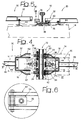
- Figure 4 is a plan view in enlarged scale of the part indicated by the arrow IV in Figure 3,
- Figure 5 is a section according to the line V-V of Figure 4,
- Figure 6 is a detail in enlarged scale of the part indicated by the arrow VI in Figure 4,
- Figure 7 is a cross section showing a variation of the acoustic insulation barrier according to the present invention,
- Figure 8 is plan view of a second variation of the present invention,
- Figure 9 is a section according to the line IX-IX of Figure 8, and
- Figure 10 is a plan view according to the arrow X of Figure 9.
- With reference to Figures 1 through 3, the
number 10 designates a rail of a railway line. The description that follows refers to a single rail but it is understood that what is stated herein applies in identical fashion to the complementary rail of the railway line. Therail 10 has aflange 12 which is fastened tosleepers 14 by means ofconventional fastening members 16. - To each
rail 10 of the railway line is associated an acoustic insulation barrier formed by twocontinuous arrays elements 22. Thearrays rail 10 at opposite parts thereof. Eachrail 10 of the railway line is associated to anouter array 18 and to aninner array 20 of sound-absorbing elements. Each railway line is therefore provided with a total of four arrays of sound-absorbing elements. - In the embodiment shown in Figures 1 through 3, the sound-absorbing
elements 22 of theouter array 20 are mutually identical. In each array, the sound-absorbingelements 22 abut at their heads in such a way as to form a continuous barrier parallel to therail 10. Each sound-absorbingelement 22 is substantially shaped as a tile which, in its cross section, is tapered from the base towards the free end. Each sound-absorbingelement 22 has a concaveinner surface 24 oriented towards therail 10. - The sound-absorbing
elements 22 can be constituted by materials of different nature. Preferably, each sound-absorbingelement 22 has acore 26 constituted by material with high sound-absorbing capacity, preferably recycled material, for instance constituted by rubbery conglomerates, synthetic mixes and the like. Thecore 26, whose function is to absorb noise, is preferably surrounded either totally or partially by anexterior shell 28 made of metallic or plastic material, preferably aluminium. In the embodiment shown in Figure 3, theshell 28 covers the entire outer surface of thecore 26. Alternatively, theshell 28 could be present solely in correspondence with the outer convex back and in correspondence with the base of the sound-absorbingelement 22, in such a way as to leave theconcave surface 24 without a rigid coating. In this way, the sound waves that propagate outwards starting from therail 10 impact directly against thesurface 24 of material with high sound absorption capacity. This allows considerably to improve the sound absorbing capacity of the barrier. The upper edge of each sound-absorbingelement 22 is tangential to a substantially horizontal plane in such a way as to form a sound containment area that is as closed as possible around the area where the noise is generated. - The
arrays elements 22 are connected to theflange 12 of the railway rail. Figures 4, 5 and 6 show a first embodiment of the system for connecting the sound-absorbingelements 22 to therail 10. The connection system comprises a plurality ofattachment devices 30 each of which comprises abracket 32 articulated to theflange 12 of therail 10 about an axis parallel to the axis of the rail. Eachbracket 32 is connected to theflange 12 of therail 10 by means of a pair ofattachments 34 positioned at opposite sides relative to themembers 16 for fastening therail 10 to asleeper 14. Eachattachment 34 comprises ablock 36 fastened to aplate 28 which extends below theflange 12 of therail 10. Theblocks 36 are fastened to theplate 38 by means ofscrews 40. Thebracket 32 has two fork shapedends 42 each of which is articulated to arespective block 36. Eachbracket 32 is also provided with asupport element 44 adjustable in height with bears down on the upper surface of therespective sleeper 14. - With reference to Figure 3, each
bracket 32 has anextension arm 46 which bears at its outer end relative to the rail 10 a pair ofattachments 48 which engage thebase 50 of a sound-absorbingelement 22 or of two elements abutting each other at the head. Theattachments 48 are fastened to thearm 46 by means of screws. - Figures 8, 9 and 10 show a variation of the acoustic insulation barrier according to the present invention. The elements corresponding to those described previously are designated by the same numeric references. The sound-absorbing
elements 22 shown in Figures 8 and 9 are identical to those described with reference to Figures 1 through 3. The variation of Figures 8-10 differs from the embodiment described above in that it uses a simpler and more economical system to connect the sound-absorbingelements 22 to therail 10. In this variation, the connection system comprises a plurality ofplates 52 which extend below theflange 12 of therail 10. Eachplate 52 is fastened to theflange 12 of therail 10 by means of a pair ofblocks 54 which act on the upper surface of theflange 12 and are fastened to thelower plate 52 by means of screws. Each end of theplate 52 bears a pair ofblocks 56 which engage thebase 50 of a sound-absorbingelement 22 or of two sound-absorbingelements 22 abutting each other by the head. Theblocks 56 are fastened to theplate 52 by means of respective screws. - The shape, the dimensions of the sound-absorbing
elements 22 and their distance from therail 10 are determined in such a way as to avoid any interference with railway vehicles. - Figure 7 shows a possible variation of the present invention in which the shape, the dimensions and the distances of the sound-absorbing elements are determined according to the outer profile of a railway vehicle with low distance from the ground, schematically indicated as 60 in Figure 7. In the variation of Figure 7, the outer sound-absorbing
elements 62 have a firstconcave surface 64 oriented towards therail 10 and positioned below the outer profile of therailway vehicle 60. Each outer sound-absorbingelement 62 also has a secondconcave surface 66 having substantially semi-circular shaped, situated laterally and externally relative to theouter profile 60. The acoustic insulation barrier shown in Figure 7 comprises and internal sound-absorbingelement 68 which extends between the tworails 10 of the railway line. The internal sound-absorbing element has two lateral portions withconcave surfaces 70 oriented towards therail 10 and acentral portion 72 that bears down on thesleeper 14 in the space between the tworails 10. Theconcave surfaces rail 10 have slightly greater height than therail 10 to avoid interference with theprofile 60 of the railway vehicle.
Claims (10)
- Acoustic insulation barrier for railway lines, characterised in that it comprises, for each rail (10), two continuous arrays (18, 20) of sound-absorbing elements (22, 62, 68) positioned at opposite parts of the rail (10) and connected to the flange (12) of the rail (10).
- Acoustic insulation barrier as claimed in claim 1, characterised in that said sound-absorbing elements (22) have respective concave surfaces (24, 62, 68) oriented towards the rail (10).
- Acoustic insulation barrier as claimed in claim 1, characterised in that each of said sound-absorbing elements (22, 62, 68) comprises a core (26) made of material with high sound absorbing capacity and an outer coating (28) which covers at least a part of said core (26).
- Acoustic insulation barrier as claimed in claim 3, characterised in that each of said sound-absorbing elements (22, 62, 68) has at least a surface (24, 64, 70) without coating oriented towards the rail (10).
- Acoustic insulation barrier as claimed in claim 1, characterised in that said arrays of sound-absorbing elements (22) are connected to the flange (12) of the rail (10) by means of a plurality of brackets (32) articulated to the flange (12) about respective axes parallel to the rail (10).
- Acoustic insulation barrier as claimed in claim 1, characterised in that said arrays (18, 20) of sound-absorbing elements (22) are connected to the flange (12) of the rail (10) by means of a plurality of plates (52) fastened to the flange (12) of the rail (10).
- Acoustic insulation barrier as claimed in claim 6, characterised in that each of said plates (52) is fastened to the flange (12) by means of a pair of blocks (54) and is provided at its ends with attachments (56) for fastening the base portion (50) of the sound-absorbing elements (22).
- Acoustic insulation barrier as claimed in claim 1, characterised in that the sound-absorbing elements (22) of the outer array (18) and of the inner array (20) are mutually identical.
- Acoustic insulation barrier as claimed in claim 1, characterised in that the sound-absorbing elements (62) forming the outer array (18) are different from the sound-absorbing elements (68) forming the inner array (20).
- Acoustic insulation barrier as claimed in claim 9, characterised in that each of the sound-absorbing elements (68) forming the inner array (20) comprises a central portion (72) that extends between two rails (10) and two lateral portions with concave surfaces (70) oriented towards the respective rails (10).
Applications Claiming Priority (2)
| Application Number | Priority Date | Filing Date | Title |
|---|---|---|---|
| ITTO20020303 | 2002-04-08 | ||
| IT2002TO000303A ITTO20020303A1 (en) | 2002-04-08 | 2002-04-08 | BARRIER FOR NOISE REDUCTION OF NOISE GENERATED AT THE IRON FLOOR FOR RAILWAY AND UNDERGROUND VEHICLES IN GENERAL. |
Publications (1)
| Publication Number | Publication Date |
|---|---|
| EP1355006A1 true EP1355006A1 (en) | 2003-10-22 |
Family
ID=27638983
Family Applications (1)
| Application Number | Title | Priority Date | Filing Date |
|---|---|---|---|
| EP03008102A Withdrawn EP1355006A1 (en) | 2002-04-08 | 2003-04-07 | An acoustic insulation barrier for railway lines |
Country Status (3)
| Country | Link |
|---|---|
| US (1) | US20040079581A1 (en) |
| EP (1) | EP1355006A1 (en) |
| IT (1) | ITTO20020303A1 (en) |
Cited By (7)
| Publication number | Priority date | Publication date | Assignee | Title |
|---|---|---|---|---|
| GB2430419A (en) * | 2005-03-12 | 2007-03-28 | Edward O'connor | Train rail guard |
| FR2904836A1 (en) * | 2006-08-09 | 2008-02-15 | Europ De Travaux Ferroviaires | Person protecting device for use during maintenance work on railway track, has net mounted on structure to form safety zone, where column of structure has assembly device fixed on shoulder flange, and spring clamp fixing rail on sleeper |
| DE102009005439A1 (en) * | 2009-01-21 | 2010-07-22 | Edilon) (Sedra Gmbh | Miniscan wall for threshold tracks |
| KR101053113B1 (en) * | 2008-12-29 | 2011-08-01 | 김다희 | Sound insulation for railway rails |
| US20120032128A1 (en) * | 2009-03-30 | 2012-02-09 | Roof Safety Systems B.V. | Safety structure for a railway line |
| EP3135813A1 (en) * | 2015-08-27 | 2017-03-01 | KRAIBURG STRAIL GmbH & Co. KG | Sound-proofing device for a track system |
| EP4276244A1 (en) | 2022-05-11 | 2023-11-15 | Acustrain, S.L. | Acoustic barrier device and acoustic barrier for railway lines |
Citations (6)
| Publication number | Priority date | Publication date | Assignee | Title |
|---|---|---|---|---|
| DE4242077A1 (en) * | 1992-12-14 | 1993-06-03 | Stuttgarter Strassenbahnen Ag | Sound proof apron for railway line - comprises vertical bracket to hold sound proof material at height to cover contact point of wheel and rail |
| WO1993016230A1 (en) * | 1992-02-13 | 1993-08-19 | Acappella Enterprises Ltd. | Noise suppression systems |
| EP0692572A1 (en) * | 1994-07-16 | 1996-01-17 | Phoenix Aktiengesellschaft | Rail construction |
| EP0867563A2 (en) * | 1997-03-25 | 1998-09-30 | Jean-Pierre Frottier | Rail track with sound absorbing proceedings |
| EP1081286A2 (en) | 1999-08-03 | 2001-03-07 | EFFEBI TECNOLOGIE Srl | Support device for rails of railway tracks |
| WO2002004749A1 (en) * | 2000-07-11 | 2002-01-17 | Z-Block Scandinavia Ab | Noise reduction means |
Family Cites Families (8)
| Publication number | Priority date | Publication date | Assignee | Title |
|---|---|---|---|---|
| US423371A (en) * | 1890-03-11 | Railway-rail | ||
| US3974963A (en) * | 1974-11-15 | 1976-08-17 | Westinghouse Air Brake Company | Railway wheel squeal suppression arrangement |
| US4142468A (en) * | 1976-04-20 | 1979-03-06 | Charles Birnstiel | Elevated rail transit guideway with noise attenuators |
| JPS5842324B2 (en) * | 1981-01-09 | 1983-09-19 | 日本国有鉄道 | noise control device |
| IT1273978B (en) * | 1995-02-28 | 1997-07-11 | Stefano Ughi | ACOUSTIC BARRIER PARTICULARLY FOR RAILWAY ARMAMENT |
| EP0964960B1 (en) * | 1997-02-19 | 2001-10-17 | Phoenix Aktiengesellschaft | Sound protection device |
| JP2900905B2 (en) * | 1997-02-26 | 1999-06-02 | 日東紡績株式会社 | Mounting structure and installation method of sound absorbing material on top of sound insulation wall |
| GB9719864D0 (en) * | 1997-09-19 | 1997-11-19 | Univ Southampton | Rail damper |
-
2002
- 2002-04-08 IT IT2002TO000303A patent/ITTO20020303A1/en unknown
-
2003
- 2003-04-07 EP EP03008102A patent/EP1355006A1/en not_active Withdrawn
- 2003-04-08 US US10/408,223 patent/US20040079581A1/en not_active Abandoned
Patent Citations (6)
| Publication number | Priority date | Publication date | Assignee | Title |
|---|---|---|---|---|
| WO1993016230A1 (en) * | 1992-02-13 | 1993-08-19 | Acappella Enterprises Ltd. | Noise suppression systems |
| DE4242077A1 (en) * | 1992-12-14 | 1993-06-03 | Stuttgarter Strassenbahnen Ag | Sound proof apron for railway line - comprises vertical bracket to hold sound proof material at height to cover contact point of wheel and rail |
| EP0692572A1 (en) * | 1994-07-16 | 1996-01-17 | Phoenix Aktiengesellschaft | Rail construction |
| EP0867563A2 (en) * | 1997-03-25 | 1998-09-30 | Jean-Pierre Frottier | Rail track with sound absorbing proceedings |
| EP1081286A2 (en) | 1999-08-03 | 2001-03-07 | EFFEBI TECNOLOGIE Srl | Support device for rails of railway tracks |
| WO2002004749A1 (en) * | 2000-07-11 | 2002-01-17 | Z-Block Scandinavia Ab | Noise reduction means |
Cited By (11)
| Publication number | Priority date | Publication date | Assignee | Title |
|---|---|---|---|---|
| GB2430419A (en) * | 2005-03-12 | 2007-03-28 | Edward O'connor | Train rail guard |
| FR2904836A1 (en) * | 2006-08-09 | 2008-02-15 | Europ De Travaux Ferroviaires | Person protecting device for use during maintenance work on railway track, has net mounted on structure to form safety zone, where column of structure has assembly device fixed on shoulder flange, and spring clamp fixing rail on sleeper |
| KR101053113B1 (en) * | 2008-12-29 | 2011-08-01 | 김다희 | Sound insulation for railway rails |
| DE102009005439A1 (en) * | 2009-01-21 | 2010-07-22 | Edilon) (Sedra Gmbh | Miniscan wall for threshold tracks |
| EP2210978A3 (en) * | 2009-01-21 | 2012-08-29 | edilon)(sedra GmbH | Protective wall for sleeper platforms |
| US20120032128A1 (en) * | 2009-03-30 | 2012-02-09 | Roof Safety Systems B.V. | Safety structure for a railway line |
| US20120037866A1 (en) * | 2009-03-30 | 2012-02-16 | Roof Safety Systems B.V. | Safety structure for a railway line |
| US9534347B2 (en) * | 2009-03-30 | 2017-01-03 | Rss Holding B.V. | Safety structure for a railway line |
| EP3135813A1 (en) * | 2015-08-27 | 2017-03-01 | KRAIBURG STRAIL GmbH & Co. KG | Sound-proofing device for a track system |
| EP4276244A1 (en) | 2022-05-11 | 2023-11-15 | Acustrain, S.L. | Acoustic barrier device and acoustic barrier for railway lines |
| WO2023217862A1 (en) | 2022-05-11 | 2023-11-16 | Acustrain, S.L. | Acoustic barrier device and acoustic barrier for railway lines |
Also Published As
| Publication number | Publication date |
|---|---|
| ITTO20020303A1 (en) | 2003-10-08 |
| US20040079581A1 (en) | 2004-04-29 |
| ITTO20020303A0 (en) | 2002-04-08 |
Similar Documents
| Publication | Publication Date | Title |
|---|---|---|
| AU2006338524B2 (en) | Sound insulating device | |
| JP2848587B2 (en) | Sound-absorbing damping material | |
| EP1355006A1 (en) | An acoustic insulation barrier for railway lines | |
| JPS5842324B2 (en) | noise control device | |
| US6810991B1 (en) | Enfolding sound barrier | |
| CA1051067A (en) | Shoe assembly | |
| JP3660335B2 (en) | Noise barrier for railway | |
| KR100291214B1 (en) | Irregular soundproofing plate | |
| EA004698B1 (en) | Guideway girder | |
| EP1229167B1 (en) | Sound absorbing construction for track | |
| EP1805368B1 (en) | Universal prefabricated monolithic antinoise barrier having air purifying effect | |
| CN102149874A (en) | A guard rail including noise-reducing measures | |
| RU201071U1 (en) | NOISE PROTECTION DEVICE FOR SORTING SLIDER CAR REDUCER | |
| NL9400910A (en) | Sound insulation assembly for a railway | |
| JP2009012535A (en) | Cowcatcher and rail vehicle having the same | |
| CN212742254U (en) | Road and bridge noise reduction device | |
| JP2017531110A (en) | Noise suppression equipment for guided transport tracks and guided transport tracks with such equipment | |
| CN213683495U (en) | Safety protective guard for building construction site | |
| CN213681703U (en) | Curved vibration-damping noise-reducing expansion device | |
| KR200198922Y1 (en) | Structure of roof side rall of automobile | |
| KR200256146Y1 (en) | Kj-3 type metallic transmission barrier panel | |
| KR100443940B1 (en) | Member for absorbing sound and vibration of rail for a concrete railway crossing | |
| JP4091836B2 (en) | Noise barrier for railway | |
| JP3678949B2 (en) | Visible noise barrier for mobile sound source | |
| KR20060007295A (en) | Reduce noise device for soundproofing walls |
Legal Events
| Date | Code | Title | Description |
|---|---|---|---|
| PUAI | Public reference made under article 153(3) epc to a published international application that has entered the european phase |
Free format text: ORIGINAL CODE: 0009012 |
|
| AK | Designated contracting states |
Kind code of ref document: A1 Designated state(s): AT BE BG CH CY CZ DE DK EE ES FI FR GB GR HU IE IT LI LU MC NL PT RO SE SI SK TR |
|
| AX | Request for extension of the european patent |
Extension state: AL LT LV MK |
|
| AKX | Designation fees paid | ||
| REG | Reference to a national code |
Ref country code: DE Ref legal event code: 8566 |
|
| STAA | Information on the status of an ep patent application or granted ep patent |
Free format text: STATUS: THE APPLICATION IS DEEMED TO BE WITHDRAWN |
|
| 18D | Application deemed to be withdrawn |
Effective date: 20040423 |