EP1354825A1 - Müllbehälter mit verstärkter Zapfen-Einheit - Google Patents
Müllbehälter mit verstärkter Zapfen-Einheit Download PDFInfo
- Publication number
- EP1354825A1 EP1354825A1 EP03400012A EP03400012A EP1354825A1 EP 1354825 A1 EP1354825 A1 EP 1354825A1 EP 03400012 A EP03400012 A EP 03400012A EP 03400012 A EP03400012 A EP 03400012A EP 1354825 A1 EP1354825 A1 EP 1354825A1
- Authority
- EP
- European Patent Office
- Prior art keywords
- edge
- unit
- pin
- ribs
- pin unit
- Prior art date
- Legal status (The legal status is an assumption and is not a legal conclusion. Google has not performed a legal analysis and makes no representation as to the accuracy of the status listed.)
- Granted
Links
- 239000002184 metal Substances 0.000 claims description 11
- 229910052751 metal Inorganic materials 0.000 claims description 11
- 239000000463 material Substances 0.000 claims description 9
- 238000003780 insertion Methods 0.000 claims description 4
- 230000037431 insertion Effects 0.000 claims description 4
- 238000000034 method Methods 0.000 claims description 2
- 238000010079 rubber tapping Methods 0.000 claims description 2
- 230000008719 thickening Effects 0.000 claims description 2
- 230000002093 peripheral effect Effects 0.000 claims 2
- 239000002699 waste material Substances 0.000 claims 2
- 230000002787 reinforcement Effects 0.000 description 5
- 230000007704 transition Effects 0.000 description 5
- 238000002347 injection Methods 0.000 description 3
- 239000007924 injection Substances 0.000 description 3
- 230000003014 reinforcing effect Effects 0.000 description 3
- 230000006641 stabilisation Effects 0.000 description 3
- 238000011105 stabilization Methods 0.000 description 3
- XEEYBQQBJWHFJM-UHFFFAOYSA-N Iron Chemical compound [Fe] XEEYBQQBJWHFJM-UHFFFAOYSA-N 0.000 description 2
- 230000004308 accommodation Effects 0.000 description 2
- 239000000243 solution Substances 0.000 description 2
- 238000005452 bending Methods 0.000 description 1
- 230000005540 biological transmission Effects 0.000 description 1
- 230000001419 dependent effect Effects 0.000 description 1
- 238000009434 installation Methods 0.000 description 1
- 229910052742 iron Inorganic materials 0.000 description 1
- 238000004519 manufacturing process Methods 0.000 description 1
- 239000003351 stiffener Substances 0.000 description 1
- 238000012549 training Methods 0.000 description 1
- 238000012546 transfer Methods 0.000 description 1
Images


Classifications
-
- B—PERFORMING OPERATIONS; TRANSPORTING
- B65—CONVEYING; PACKING; STORING; HANDLING THIN OR FILAMENTARY MATERIAL
- B65F—GATHERING OR REMOVAL OF DOMESTIC OR LIKE REFUSE
- B65F1/00—Refuse receptacles; Accessories therefor
- B65F1/12—Refuse receptacles; Accessories therefor with devices facilitating emptying
- B65F1/122—Features allowing the receptacle to be lifted and subsequently tipped by associated means on a vehicle
Definitions
- the invention relates to so-called garbage bulk containers.
- garbage containers hold about 1,000 liters and can therefore in the filled state reach a weight of more than a ton.
- the emptying takes place in that on the outside of two opposite Side walls of the container projecting outward receiving pin are arranged by two fork-shaped receptacles of the evacuation vehicles taken and thus the entire container lifted, tilted and is emptied. Accordingly, the receiving pin must be very stable be formed and connected to the container. For reasons of emptying process the receiving pins must be approximately in the middle of the front side Walls are located, so an area of usually thin-walled and without larger stiffeners is formed.
- the receiving pin not in one piece in the production of the container - which is usually done by means of plastic injection molding- form, but instead a separate, shell-shaped injection molded part, the so-called pin unit, in addition to a tubular metal reinforcement housed as a pin to attach to the outside of the body, especially to screw.
- this pin unit among the double to insert cranked, outwardly projecting edge and thereby a positive connection of these two parts in the upper region of the pin unit to accomplish.
- the container and In particular, the pin unit so educate that a very stable connection of the pin to the container at the lowest possible weight and installation costs and size of the pin unit is achieved, as well as a forwarding the forces in the most stable zones of the container.
- the transition between the wide, upper area and the narrower lower area either V-shaped or T-shaped with strongly rounded Transition designed, wherein preferably the radially obliquely upward Ridges are directed tangentially to the transition radius of the outer wall.
- a grid can be created by the horizontal and vertical ribs arise, with a socket in one of the resulting compartments is centered, and in particular its corners is radially ribbed, in particular Also a horizontal and vertical rib reaches this socket.
- the in the central bush made of plastic inserted metal reinforcement in Shape of a piece of pipe is inserted into the socket just fit and is supported in the mounted state on its outer front side on the inner surface the continuous outer wall of the unit from and on its inner end face the wall of the corpus.
- the outer wall initially points a bend on the lower free end of the downward facing Edge of the body can be applied and positively locking forces on this support can transfer.
- the upper part of the unit can be inserted by inserting one in the horizontal direction, So the width of the upper part extending, metal part done, either a pipe, an open profile or a flat material, then with lying cross-section.
- Such reinforcement can be accommodated in a corresponding receiving space of the open back of the cup-shaped pin unit are inserted, wherein then, however, the need exists in this area the vertical or oblique to interrupt upwardly extending ribs which serve to reinforce which drastically worsens stabilization by the ribs.
- such a reinforcement in the longitudinal direction of the upper part are inserted through an end opening in the upper part, before the assembly of the pin unit to the container.
- the insertion opening placed so high that they are below the bent after assembly Rand disappears and is therefore no longer visible and accessible.
- Another possibility is to interpose a lying sheet, an angle profile or a downwardly open U-profile between the Interior of the downwardly open edge and there inserted from below Top of the pin unit, which according to the wall thickness of this Material needs to be sized smaller.
- the width of the upper part is chosen as large as possible, and reaches into Practice best to appropriate cross braces in the interior of the after bottom open edge, for example, in the shape of the left and right outside the end wall existing handles or receiving openings for pluggable Handles in the edge are present.
- the opening angle of the V is in the range above the Spigot preferably chosen so that in this area the outer edge the line between the center of the pin and the free outer end of the pin upper part, so the upper corners of the unit, lies.
- the outer edge is at all designs without kink and with the largest possible rounding in the supervision Equipped to equip the power line in the longitudinal direction of the edge favor and hinder its buckling.
- the side wall 25 of the body 1 ends at the top in one double outwards downwards bent edge 7, which is thus a horizontal after outside facing connecting leg and one at the free end after pointing down, freely ending below and running in the distance to the side wall includes vertical leg.
- the cup-shaped plastic part which represents the pin unit 29 substantially, with its upper Area 29a as far as possible pushed. It can be seen that due to a crank 41 of the outer wall 40 of the unit 29, the unit 29 below the edge 7 projects outwards and in particular with its outer edge flush, and in turn the receiving pin 28 itself protrudes further outwards.
- this edge 7 substantially goes over the entire width of the side wall 25, but the interior through mounting holes 13, the pairs in the left and right end are arranged and serve the insertion of stakes 6, interrupted.
- the pin unit 29 extends therebetween throughout the remaining one Width and lies with the crank 41 of its outer wall 40 at the lower end of the free leg of the edge 7 and / or with its upper edge at the bottom Edge 7 pointing groove bottom.
- Screws 43 are from the inside of the wall 25 through it screwed in and end in blind holes 34 of the pin unit 29, as for Body open, cupped, ribbed, outside of a closed Outside wall 40 framed, plastic injection molded part is designed.
- the central sleeve 30 is formed integrally with the unit 29, in which inserted from the open side of the reinforcing metal tube 31 fit is.
- the blind holes 34 are formed.
- ribs 32 a, c are the am most loaded ribs and go tangentially into the edge at the inner radius at Transition between vertical middle leg and transverse upper Area of the unit 29 over and from there to the upper inner corners the unit 29 and the edge 33 there.
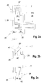
- Fig. 2a shows an angle profile 37 ', which on the outer surface of the side wall and is arranged under the transverse leg of the side edge and positively merely by the upper edge 33 of the units pressed from below 29 is held.
- an additional stiffening element in the upper Part 29a be arranged:
- FIG. 3 shows in the right part of an open towards the rear receiving space 38 for a flat material 36, which lies flat with in the mounted state Cross-section is inserted, since the bending forces then in the direction of its largest Cross-sectional extension occur.
- the receiving space 38 is as accurate as possible to the dimensions of the reinforcing member customized.
- the disadvantage here is the necessary interruption of vertically or obliquely upwardly extending ribs in this area.
- the edge 33 of the unit 29 has an end opening 39, which is preferably so high that it is higher in the assembled state than that lower edge of the edge 7 and thus neither accessible nor visible.
- the unit can be assembled by first placing the metal tube 31 is inserted from the open back into the socket 30, previously or thereafter in its longitudinal extent the profile 37 or flat material 36 of the frontal opening 39 is inserted into the unit 29 and thereafter the unit 29 is inserted with its upper portion under the edge 7 and in this Position screwed by means of screws 43 from the inside of the side wall 25 becomes.
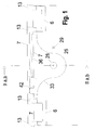
- Fig. 1 shows a stiffening option in addition or without inserted in the upper part Metal part:
- stiffening webs 42 between the outer free around the leg of the edge. 7 arranged on the side wall. Only in the area between these stiffening webs 42 reaches the top 29a to the very top in the interior of the Groove of the edge 7 in, which affects its stability, however.
- Fig. 2b shows a solution in which the approximately rectangular free cross-section the edge 7 for stiffening webs 42 of the edge on the one hand and 42 'of the unit 29 on the other hand is split:
- the inner wall 25 indicative, diagonally divided, triangular upper area is available for corresponding triangular stiffening webs 42 of the edge 7, while at the same position or even the other offset the lower triangular region for stiffening webs 42 'of the units 29 is available, the upper edge, however, in the area between the webs 42 to the side wall 25 may extend.
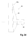
- Fig. 2d shows that the outer wall 40 from the neck of the pin (28) not at right angles, but at an obtuse angle can run to the outside, so that a tapered on the pin 28 cone, to improve the force transmission, especially down the edge 33 ends and at the top of the upper portion 29 a, which under the edge 7 of the body 1 can be pushed.
- Fig. 4 shows - in the same direction as Fig. 3, ie from the open rear - another form of ribbing.
- a horizontal rib 32q extends at the level of the lower one Edge of the upper area, and goes into the edge 33 tangentially at the site over, on which this approximately horizontally reaches the front side of the unit 29.
- Another horizontal rib 32p is spaced above it but even deeper than the return in the outer skin 40, which is free after supported down leg of the edge.
- Thickened screw receptacles are preferably in this highest lying horizontal Rib 32b at the crossing points with the vertical ribs 35, 32b formed, as well as near the front end of this horizontal rib 32p.
- One of the screw receptacles preferably one of the lowest-lying Screw, is over the back protruding and in particular conical formed above as centering, as explained with reference to FIG. 2a.
Landscapes
- Engineering & Computer Science (AREA)
- Mechanical Engineering (AREA)
- Refuse Receptacles (AREA)
- Rigid Containers With Two Or More Constituent Elements (AREA)
- Processing Of Solid Wastes (AREA)
Abstract
Description
- Fig. 1:
- Eine Aufsicht auf eine Seitenfläche des Behälters mit Zapfen-Einheit,
- Fig. 2:
- vertikale Schnittdarstellungen bzw. Seitenansichten durch die Zapfen-Einheit
- Fig. 3:
- eine Aufsicht auf die Zapfen-Einheit von der Rückseite her, und
- Fig. 4:
- eine Aufsicht auf eine anders gestaltete Zapfeneinheit von der Rückseite her.
- 1
- Korpus
- 20
- Großbehälter
- 25
- Seitenwand
- 28
- Aufnahme-Zapfen
- 29
- Zapfen-Einheit
- 30
- Buchse
- 31
- Metallrohr
- 32
- AB Rippe
- 33
- Rand
- 34
- Sackloch
- 35
- Vertikalrippe
- 36
- Flachmaterial
- 37
- Profil
- 37'
- Winkelprofil
- 38
- Aufnahmeraum
- 38'
- Aufnahmeraum
- 39
- stirnseitige Öffnung
- 40
- Außenwand
- 41
- Kröpfung
- 42, 42'
- Versteifungssteg
- 43
- Schraube
Claims (11)
- Müllbehälter, insbesondere Großbehälter (20), mit einem Korpus (1), an dessen voneinander wegweisenden Seitenwänden (25) je ein Aufnahme-Zapfen (28) in Form einer der den Aufnahme-Zapfen (28) seitlich abstützenden Zapfen-Einheit (29) montiert ist, die den nach außen überstehenden und nach unten gekröpften Rand (7) des Korpus (1) untergreift,
dadurch gekennzeichnet, dass
die Zapfen-Einheit (29) im oberen, den Rand (7) untergreifenden, Bereich (29a) in der Aufsicht auf die Einheit (29) eine wesentlich größere Breite, insbesondere mindestens die doppelte Breite, aufweist als im unteren Bereich (29b) auf der Höhe des Aufnahmezapfens (28). - Müllbehälter, insbesondere Großbehälter (20), mit einem Korpus (1), an dessen voneinander wegweisenden Seitenwänden (25) je ein Aufnahme-Zapfen (28) in Form einer der den Aufnahme-Zapfen (28) seitlich abstützenden Zapfen-Einheit (29) montiert ist, die den nach außen überstehenden und nach unten gekröpften Rand (7) des Korpus (1) untergreift,
dadurch gekennzeichnet, dass
der obere Bereich (29a) so breit wie möglich ausgebildet ist und insbesondere seitlich bis zu den im Rand (7) angeordneten Befestigungsöffnungen (13) für die seitlichen Griffe reicht, die den Rand (7) quer verstreben. - Müllbehälter nach Anspruch 1 oder 2,
dadurch gekennzeichnet, dassdie Zapfen-Einheit (29) ein topfförmiges, im Inneren verripptes, Kunststoff-Spritzgussteil mit der offenen Seite zum Korpus (1) hin ist und insbesondere in seiner zentralen Buchse (30) ein Metallrohr (31) aufgenommen hält, und insbesonderedie Zapfen-Einheit (29) T- oder V-förmig gestaltet ist. - Müllbehälter nach einem der vorhergehenden Ansprüche,
dadurch gekennzeichnet, dassim topfförmigen Inneren der Zapfeneinheit (29) lotrecht zu deren Hauptebene stehende Rippen (32a, b, c...) angeordnet sind, die radial, insbesondere mit gleichmäßigem Winkelabstand, von der Buchse (30) nach außen streben, insbesondere bis zum umlaufenden, insbesondere geschlossen umlaufenden, Rand (33) der Zapfen-Einheit, und insbesonderein der Einheit (29) zusätzlich Vertikalrippen (35) vom oberen Rand (33) vertikal nach unten bis zum unteren Rand (33) durchgehend angeordnet sind. - Müllbehälter nach einem der vorhergehenden Ansprüche,
dadurch gekennzeichnet, dassin der Einheit (29) zusätzliche Horizontalrippen (32 l - q) angeordnet sind, die jeweils im linken und rechten Rand enden, und/oder insbesonderedie von der Buchse (30) radial diagonal nach außen strebenden Rippen (32a'...) bis zum nächsten Kreuzungspunkt zwischen horizontalen (32m...) und vertikalen (35) Rippen reichen, und/oder insbesondereeine horizontale Rippe (32 q) auf der Höhe des unteren Randes des oberen Bereiches (29a), also dem unteren Rand des stirnseitigen Endes, der Einheit (29) durchgehend angeordnet ist, und/oder insbesondereeine horizontale Rippe (32p) oberhalb des unteren Endes des oberen Bereiches (29a), also oberhalb des unteren Randes der Stirnseite der Einheit (29), angeordnet ist, und insbesondere in dieser horizontalen Rippe (32b) in den Kreuzungspunkten mit den vertikalen Rippen (35) und insbesondere nahe des stirnseitigen äußeren Endes Sacklöcher (34) in verdickten Stellen angeordnet sind, und insbesondere ein Sackloch in der Mitte zwischen vertikaler Mittelebene und äußerem Rand. - Müllbehälter nach einem der vorhergehenden Ansprüche,
dadurch gekennzeichnet, dassSacklöcher (34) in der horizontal von der Buchse (30) nach außen strebenden horizontalen Rippe (32n) sowie in den beiden seitlich der Buchse vertikal verlaufenden Rippen (35), jeweils insbesondere kurz vor Erreichen des seitlich bzw. unteren Randes (33), in den diese Rippen übergehen, angeordnet sind, und insbesonderevon der offenen Seite her Sacklöcher (34) zum Verschrauben mit dem Korpus in den verdickten Treffpunkten der radialen Rippen (32a, b) mit dem umlaufenden Rand (33) und/oder mit den vertikalen Rippen (35), insbesondere vom Rand (33) etwas nach innen zurückversetzt, ausgebildet sind. - Müllbehälter nach einem der vorhergehenden Ansprüche,
dadurch gekennzeichnet, dassdie mittlere vertikale Rippe (32b), und insbesondere auch nicht die anderen vertikalen Rippen (35), auf der Längsmittelebene nicht über die oberste horizontale Rippe (32p) hinausreichen, und insbesondereeine der Verdickungen der Rippen zum Aufnehmen einer Verschraubung über die hintere, offene Rückseite der Einheit (29) hinaus konisch vorsteht als Zentrierhilfe zum Einschieben in eine Bohrung der Seitenwand (25) des Korpus (1). - Müllbehälter nach einem der vorhergehenden Ansprüche,
dadurch gekennzeichnet, dassim oberen Bereich (29a) ein in Verlaufsrichtung des oberen Bereiches, im montierten Zustand also in der Horizontalen verlaufender, Aufnahmeraum zur Aufnahme eines über vorzugsweise die gesamte Länge des oberen Bereiches durchgehendes Profil (37) oder Flachmaterial (36) - dann mit liegendem Querschnitt - vorgesehen ist, welches insbesondere bis zu den Innenseiten des umlaufenden Randes (33) reicht, und/oder insbesondereder Aufnahmeraum (38) zur offenen Rückseite der Zapfen-Einheit (29) hin offen ist, und/oder insbesondereder Aufnahmeraum (38) nur stirnseitig auf einer der Stirnseiten des oberen Bereiches (29a), insbesondere über eine oberhalb des unteren Randes (7) liegende stirnseitige Öffnung (39), zugänglich ist und insbesondere von den vertikalen Rippen (35) und/oder den kreuzenden radialen Rippen (32) allseitig umschlossen ist. - Müllbehälter nach einem der vorhergehenden Ansprüche,
dadurch gekennzeichnet, dass
ein Winkelprofil (37') zwischen den oberen Rand der Zapfen-Einheit (29) und den ihn umgreifenden Rand (7) der Wand (25) eingelegt ist. - Müllbehälter nach einem der vorhergehenden Ansprüche,
dadurch gekennzeichnet, dass
im Querschnitt betrachtet die Außenwand (40) der Zapfen-Einheit (29) im oberen Bereich wenigstens eine Kröpfung (41) so aufweist, dass der eine Schenkel der Kröpfung gegen das freie nach unten weisende Ende des Randes (7) über die gesamte Breite anpressbar ist. - Verfahren zum Montieren der Zapfen-Einheit (29) mit folgenden Schritten:Einsetzen des Metallrohres (31) in die Buchse (30) der Zapfen-Einheit (29),ggf. Einlegen des Flachmaterials (36) oder Profiles (37), insbesondere durch stirnseitiges Einschieben,Einschieben der Zapfen-Einheit (29) von unten unter den Rand (7) des Korpus (1) und Hochdrücken bis zum Anschlag,Verschrauben der Zapfen-Einheit (29) von der Innenseite des Korpus her mittels insbesondere selbstschneidender Schrauben (43) oder insbesonderealternativ zum Einbringen des Flachmaterials (36) oder Profiles (37) in die Zapfen-Einheit (29) das Metallteil (36 bzw. 37) beim Einschieben der Zapfen-Einheit (29) zwischen Zapfen-Einheit und Rand (7) eingelegt wird.
Applications Claiming Priority (2)
| Application Number | Priority Date | Filing Date | Title |
|---|---|---|---|
| DE20205927U | 2002-04-16 | ||
| DE20205927U DE20205927U1 (de) | 2002-04-16 | 2002-04-16 | Verstärkte Zapfen-Aufnahme |
Publications (2)
| Publication Number | Publication Date |
|---|---|
| EP1354825A1 true EP1354825A1 (de) | 2003-10-22 |
| EP1354825B1 EP1354825B1 (de) | 2017-01-04 |
Family
ID=7970100
Family Applications (1)
| Application Number | Title | Priority Date | Filing Date |
|---|---|---|---|
| EP03400012.5A Expired - Lifetime EP1354825B1 (de) | 2002-04-16 | 2003-04-16 | Müllbehälter mit verstärkter Zapfen-Einheit |
Country Status (2)
| Country | Link |
|---|---|
| EP (1) | EP1354825B1 (de) |
| DE (1) | DE20205927U1 (de) |
Cited By (1)
| Publication number | Priority date | Publication date | Assignee | Title |
|---|---|---|---|---|
| EP4282782A1 (de) | 2022-05-25 | 2023-11-29 | ESE World B.V. | Grossabfallsammelbehälter |
Families Citing this family (3)
| Publication number | Priority date | Publication date | Assignee | Title |
|---|---|---|---|---|
| DE10216804C1 (de) * | 2002-04-16 | 2003-10-02 | Sulo Umwelttechnik Gmbh & Co Kg | Bausatz mit Steckgriffen |
| DE20205927U1 (de) * | 2002-04-16 | 2002-07-04 | SULO Umwelttechnik GmbH & Co. KG, 32051 Herford | Verstärkte Zapfen-Aufnahme |
| IT201700007588A1 (it) * | 2017-01-24 | 2018-07-24 | Antonio Luigi Piero Maria Foresti | Sistema di sollevamento per cassonetti e contenitori di rifiuti con perni di sollevamento montabili manualmente |
Citations (2)
| Publication number | Priority date | Publication date | Assignee | Title |
|---|---|---|---|---|
| DE3001703A1 (de) * | 1980-01-18 | 1981-07-23 | Sulo Eisenwerk Streuber & Lohmann Gmbh & Co Kg, 4900 Herford | Grossraum-muellbehaelter aus kunststoff |
| DE20205927U1 (de) * | 2002-04-16 | 2002-07-04 | SULO Umwelttechnik GmbH & Co. KG, 32051 Herford | Verstärkte Zapfen-Aufnahme |
Family Cites Families (1)
| Publication number | Priority date | Publication date | Assignee | Title |
|---|---|---|---|---|
| DE8001259U1 (de) | 1980-01-18 | 1981-07-09 | Sulo Eisenwerk Streuber & Lohmann Gmbh & Co Kg, 4900 Herford | Grossraum-muellbehaelter aus kunststoff |
-
2002
- 2002-04-16 DE DE20205927U patent/DE20205927U1/de not_active Expired - Lifetime
-
2003
- 2003-04-16 EP EP03400012.5A patent/EP1354825B1/de not_active Expired - Lifetime
Patent Citations (2)
| Publication number | Priority date | Publication date | Assignee | Title |
|---|---|---|---|---|
| DE3001703A1 (de) * | 1980-01-18 | 1981-07-23 | Sulo Eisenwerk Streuber & Lohmann Gmbh & Co Kg, 4900 Herford | Grossraum-muellbehaelter aus kunststoff |
| DE20205927U1 (de) * | 2002-04-16 | 2002-07-04 | SULO Umwelttechnik GmbH & Co. KG, 32051 Herford | Verstärkte Zapfen-Aufnahme |
Cited By (2)
| Publication number | Priority date | Publication date | Assignee | Title |
|---|---|---|---|---|
| EP4282782A1 (de) | 2022-05-25 | 2023-11-29 | ESE World B.V. | Grossabfallsammelbehälter |
| EP4282782B1 (de) * | 2022-05-25 | 2026-05-13 | ESE World B.V. | Grossabfallsammelbehälter |
Also Published As
| Publication number | Publication date |
|---|---|
| DE20205927U1 (de) | 2002-07-04 |
| EP1354825B1 (de) | 2017-01-04 |
Similar Documents
| Publication | Publication Date | Title |
|---|---|---|
| DE60200454T2 (de) | Palettenbehälter für Flüssigkeiten | |
| DE9112561U1 (de) | Kastenförmiger Behälter aus Kunststoff | |
| WO2004026711A1 (de) | Grossvolumiger behälter mit zwei behälterteilen und einer stützvorrichtung im verbindungsbereich | |
| DE202008011835U1 (de) | Stütze für Flüssigkeitsschutzwand | |
| DE102013200336A1 (de) | Rahmenmodul für einen Schrank oder eine Schublade | |
| EP3491970B1 (de) | Regalbox | |
| EP2767483B1 (de) | Stapelbarer Transportbehälter | |
| EP1354825B1 (de) | Müllbehälter mit verstärkter Zapfen-Einheit | |
| EP3527734A1 (de) | Entwässerungsrinne mit aufsteckzarge | |
| DE20105030U1 (de) | Vorrichtung zur Lagerung von Flüssigkeiten | |
| EP2509880B1 (de) | Grossladungsträger | |
| EP1984686A2 (de) | Kältegerät und fachboden dafür | |
| DE20205928U1 (de) | Müllbehälter-Korpus | |
| DE29503005U1 (de) | Speichertank für Regenwasser | |
| EP0474967A1 (de) | Ski | |
| EP0538511A1 (de) | Komposter | |
| EP3753857A1 (de) | Wandelement eines paletten-aufsatzrahmens, und paletten-aufsatzrahmen | |
| EP0571650B1 (de) | Zerlegbares Tischsystem | |
| EP2338799B1 (de) | Behälter aus thermoplastischem Kunststoff | |
| DE8525402U1 (de) | Bausatz für eine rollbare Transportplattform | |
| DE102016104889B4 (de) | Eckverbinder | |
| DE19848011C2 (de) | Nachrüst-Chip | |
| CH691056A5 (de) | Stapelbarer Kunststoffbehälter mit Aufnahmemitteln für Verstärkungselementen. | |
| EP4338647A1 (de) | Wascheimer | |
| DE202004016046U1 (de) | Aufsatzrahmen und Wandungselemente für Aufsatzrahmen |
Legal Events
| Date | Code | Title | Description |
|---|---|---|---|
| PUAI | Public reference made under article 153(3) epc to a published international application that has entered the european phase |
Free format text: ORIGINAL CODE: 0009012 |
|
| AK | Designated contracting states |
Kind code of ref document: A1 Designated state(s): AT BE BG CH CY CZ DE DK EE ES FI FR GB GR HU IE IT LI LU MC NL PT RO SE SI SK TR |
|
| AX | Request for extension of the european patent |
Extension state: AL LT LV MK |
|
| 17P | Request for examination filed |
Effective date: 20031201 |
|
| AKX | Designation fees paid |
Designated state(s): AT BE BG CH CY CZ DE DK EE ES FI FR GB GR HU IE IT LI LU MC NL PT RO SE SI SK TR |
|
| AXX | Extension fees paid |
Extension state: LV Payment date: 20030416 Extension state: LT Payment date: 20030416 |
|
| RAP1 | Party data changed (applicant data changed or rights of an application transferred) |
Owner name: SULO UMWELTTECHNIK GMBH |
|
| 17Q | First examination report despatched |
Effective date: 20081015 |
|
| GRAP | Despatch of communication of intention to grant a patent |
Free format text: ORIGINAL CODE: EPIDOSNIGR1 |
|
| INTG | Intention to grant announced |
Effective date: 20160721 |
|
| GRAS | Grant fee paid |
Free format text: ORIGINAL CODE: EPIDOSNIGR3 |
|
| GRAA | (expected) grant |
Free format text: ORIGINAL CODE: 0009210 |
|
| AK | Designated contracting states |
Kind code of ref document: B1 Designated state(s): AT BE BG CH CY CZ DE DK EE ES FI FR GB GR HU IE IT LI LU MC NL PT RO SE SI SK TR |
|
| AX | Request for extension of the european patent |
Extension state: LT LV |
|
| REG | Reference to a national code |
Ref country code: GB Ref legal event code: FG4D Free format text: NOT ENGLISH |
|
| REG | Reference to a national code |
Ref country code: CH Ref legal event code: EP |
|
| REG | Reference to a national code |
Ref country code: AT Ref legal event code: REF Ref document number: 858998 Country of ref document: AT Kind code of ref document: T Effective date: 20170115 |
|
| REG | Reference to a national code |
Ref country code: IE Ref legal event code: FG4D Free format text: LANGUAGE OF EP DOCUMENT: GERMAN |
|
| REG | Reference to a national code |
Ref country code: DE Ref legal event code: R096 Ref document number: 50315602 Country of ref document: DE |
|
| REG | Reference to a national code |
Ref country code: NL Ref legal event code: FP |
|
| REG | Reference to a national code |
Ref country code: FR Ref legal event code: PLFP Year of fee payment: 15 |
|
| REG | Reference to a national code |
Ref country code: LT Ref legal event code: MG9D |
|
| PG25 | Lapsed in a contracting state [announced via postgrant information from national office to epo] |
Ref country code: GR Free format text: LAPSE BECAUSE OF FAILURE TO SUBMIT A TRANSLATION OF THE DESCRIPTION OR TO PAY THE FEE WITHIN THE PRESCRIBED TIME-LIMIT Effective date: 20170405 Ref country code: FI Free format text: LAPSE BECAUSE OF FAILURE TO SUBMIT A TRANSLATION OF THE DESCRIPTION OR TO PAY THE FEE WITHIN THE PRESCRIBED TIME-LIMIT Effective date: 20170104 |
|
| PG25 | Lapsed in a contracting state [announced via postgrant information from national office to epo] |
Ref country code: BG Free format text: LAPSE BECAUSE OF FAILURE TO SUBMIT A TRANSLATION OF THE DESCRIPTION OR TO PAY THE FEE WITHIN THE PRESCRIBED TIME-LIMIT Effective date: 20170404 Ref country code: SE Free format text: LAPSE BECAUSE OF FAILURE TO SUBMIT A TRANSLATION OF THE DESCRIPTION OR TO PAY THE FEE WITHIN THE PRESCRIBED TIME-LIMIT Effective date: 20170104 Ref country code: ES Free format text: LAPSE BECAUSE OF FAILURE TO SUBMIT A TRANSLATION OF THE DESCRIPTION OR TO PAY THE FEE WITHIN THE PRESCRIBED TIME-LIMIT Effective date: 20170104 Ref country code: PT Free format text: LAPSE BECAUSE OF FAILURE TO SUBMIT A TRANSLATION OF THE DESCRIPTION OR TO PAY THE FEE WITHIN THE PRESCRIBED TIME-LIMIT Effective date: 20170504 |
|
| REG | Reference to a national code |
Ref country code: DE Ref legal event code: R097 Ref document number: 50315602 Country of ref document: DE |
|
| PG25 | Lapsed in a contracting state [announced via postgrant information from national office to epo] |
Ref country code: EE Free format text: LAPSE BECAUSE OF FAILURE TO SUBMIT A TRANSLATION OF THE DESCRIPTION OR TO PAY THE FEE WITHIN THE PRESCRIBED TIME-LIMIT Effective date: 20170104 Ref country code: SK Free format text: LAPSE BECAUSE OF FAILURE TO SUBMIT A TRANSLATION OF THE DESCRIPTION OR TO PAY THE FEE WITHIN THE PRESCRIBED TIME-LIMIT Effective date: 20170104 Ref country code: IT Free format text: LAPSE BECAUSE OF FAILURE TO SUBMIT A TRANSLATION OF THE DESCRIPTION OR TO PAY THE FEE WITHIN THE PRESCRIBED TIME-LIMIT Effective date: 20170104 Ref country code: RO Free format text: LAPSE BECAUSE OF FAILURE TO SUBMIT A TRANSLATION OF THE DESCRIPTION OR TO PAY THE FEE WITHIN THE PRESCRIBED TIME-LIMIT Effective date: 20170104 |
|
| PLBE | No opposition filed within time limit |
Free format text: ORIGINAL CODE: 0009261 |
|
| STAA | Information on the status of an ep patent application or granted ep patent |
Free format text: STATUS: NO OPPOSITION FILED WITHIN TIME LIMIT |
|
| PG25 | Lapsed in a contracting state [announced via postgrant information from national office to epo] |
Ref country code: DK Free format text: LAPSE BECAUSE OF FAILURE TO SUBMIT A TRANSLATION OF THE DESCRIPTION OR TO PAY THE FEE WITHIN THE PRESCRIBED TIME-LIMIT Effective date: 20170104 |
|
| REG | Reference to a national code |
Ref country code: CH Ref legal event code: PL |
|
| 26N | No opposition filed |
Effective date: 20171005 |
|
| REG | Reference to a national code |
Ref country code: IE Ref legal event code: MM4A |
|
| PG25 | Lapsed in a contracting state [announced via postgrant information from national office to epo] |
Ref country code: MC Free format text: LAPSE BECAUSE OF FAILURE TO SUBMIT A TRANSLATION OF THE DESCRIPTION OR TO PAY THE FEE WITHIN THE PRESCRIBED TIME-LIMIT Effective date: 20170104 |
|
| PG25 | Lapsed in a contracting state [announced via postgrant information from national office to epo] |
Ref country code: SI Free format text: LAPSE BECAUSE OF FAILURE TO SUBMIT A TRANSLATION OF THE DESCRIPTION OR TO PAY THE FEE WITHIN THE PRESCRIBED TIME-LIMIT Effective date: 20170104 Ref country code: CH Free format text: LAPSE BECAUSE OF NON-PAYMENT OF DUE FEES Effective date: 20170430 Ref country code: LI Free format text: LAPSE BECAUSE OF NON-PAYMENT OF DUE FEES Effective date: 20170430 Ref country code: LU Free format text: LAPSE BECAUSE OF NON-PAYMENT OF DUE FEES Effective date: 20170416 |
|
| REG | Reference to a national code |
Ref country code: FR Ref legal event code: PLFP Year of fee payment: 16 |
|
| PG25 | Lapsed in a contracting state [announced via postgrant information from national office to epo] |
Ref country code: IE Free format text: LAPSE BECAUSE OF NON-PAYMENT OF DUE FEES Effective date: 20170416 |
|
| PG25 | Lapsed in a contracting state [announced via postgrant information from national office to epo] |
Ref country code: HU Free format text: LAPSE BECAUSE OF FAILURE TO SUBMIT A TRANSLATION OF THE DESCRIPTION OR TO PAY THE FEE WITHIN THE PRESCRIBED TIME-LIMIT; INVALID AB INITIO Effective date: 20030416 |
|
| PG25 | Lapsed in a contracting state [announced via postgrant information from national office to epo] |
Ref country code: CY Free format text: LAPSE BECAUSE OF NON-PAYMENT OF DUE FEES Effective date: 20170104 |
|
| PG25 | Lapsed in a contracting state [announced via postgrant information from national office to epo] |
Ref country code: TR Free format text: LAPSE BECAUSE OF FAILURE TO SUBMIT A TRANSLATION OF THE DESCRIPTION OR TO PAY THE FEE WITHIN THE PRESCRIBED TIME-LIMIT Effective date: 20170104 |
|
| PGFP | Annual fee paid to national office [announced via postgrant information from national office to epo] |
Ref country code: CZ Payment date: 20200415 Year of fee payment: 18 Ref country code: NL Payment date: 20200427 Year of fee payment: 18 |
|
| PGFP | Annual fee paid to national office [announced via postgrant information from national office to epo] |
Ref country code: BE Payment date: 20200427 Year of fee payment: 18 Ref country code: GB Payment date: 20200427 Year of fee payment: 18 |
|
| PGFP | Annual fee paid to national office [announced via postgrant information from national office to epo] |
Ref country code: AT Payment date: 20200421 Year of fee payment: 18 |
|
| REG | Reference to a national code |
Ref country code: NL Ref legal event code: MM Effective date: 20210501 |
|
| REG | Reference to a national code |
Ref country code: AT Ref legal event code: MM01 Ref document number: 858998 Country of ref document: AT Kind code of ref document: T Effective date: 20210416 |
|
| GBPC | Gb: european patent ceased through non-payment of renewal fee |
Effective date: 20210416 |
|
| REG | Reference to a national code |
Ref country code: BE Ref legal event code: MM Effective date: 20210430 |
|
| PG25 | Lapsed in a contracting state [announced via postgrant information from national office to epo] |
Ref country code: AT Free format text: LAPSE BECAUSE OF NON-PAYMENT OF DUE FEES Effective date: 20210416 Ref country code: GB Free format text: LAPSE BECAUSE OF NON-PAYMENT OF DUE FEES Effective date: 20210416 Ref country code: CZ Free format text: LAPSE BECAUSE OF NON-PAYMENT OF DUE FEES Effective date: 20210416 |
|
| PG25 | Lapsed in a contracting state [announced via postgrant information from national office to epo] |
Ref country code: NL Free format text: LAPSE BECAUSE OF NON-PAYMENT OF DUE FEES Effective date: 20210501 |
|
| PG25 | Lapsed in a contracting state [announced via postgrant information from national office to epo] |
Ref country code: BE Free format text: LAPSE BECAUSE OF NON-PAYMENT OF DUE FEES Effective date: 20210430 |
|
| PGFP | Annual fee paid to national office [announced via postgrant information from national office to epo] |
Ref country code: FR Payment date: 20220429 Year of fee payment: 20 Ref country code: DE Payment date: 20220420 Year of fee payment: 20 |
|
| REG | Reference to a national code |
Ref country code: DE Ref legal event code: R071 Ref document number: 50315602 Country of ref document: DE |