EP1353435B1 - Verfahren und Vorrichtung zum Wicklungsabschluss bei außenbewickelten Multipolstatoren - Google Patents
Verfahren und Vorrichtung zum Wicklungsabschluss bei außenbewickelten Multipolstatoren Download PDFInfo
- Publication number
- EP1353435B1 EP1353435B1 EP02425221A EP02425221A EP1353435B1 EP 1353435 B1 EP1353435 B1 EP 1353435B1 EP 02425221 A EP02425221 A EP 02425221A EP 02425221 A EP02425221 A EP 02425221A EP 1353435 B1 EP1353435 B1 EP 1353435B1
- Authority
- EP
- European Patent Office
- Prior art keywords
- wire
- axis
- terminal
- clamp
- stator
- Prior art date
- Legal status (The legal status is an assumption and is not a legal conclusion. Google has not performed a legal analysis and makes no representation as to the accuracy of the status listed.)
- Expired - Lifetime
Links
- 238000000034 method Methods 0.000 title claims abstract description 22
- 230000005405 multipole Effects 0.000 title claims description 23
- 238000004804 winding Methods 0.000 claims abstract description 62
- 241001155433 Centrarchus macropterus Species 0.000 claims abstract description 51
- 230000005294 ferromagnetic effect Effects 0.000 claims description 7
- WABPQHHGFIMREM-UHFFFAOYSA-N lead(0) Chemical compound [Pb] WABPQHHGFIMREM-UHFFFAOYSA-N 0.000 claims description 3
- 230000000903 blocking effect Effects 0.000 description 9
- 238000013459 approach Methods 0.000 description 4
- 238000005452 bending Methods 0.000 description 2
- 230000008878 coupling Effects 0.000 description 1
- 238000010168 coupling process Methods 0.000 description 1
- 238000005859 coupling reaction Methods 0.000 description 1
- 230000006698 induction Effects 0.000 description 1
- 210000003141 lower extremity Anatomy 0.000 description 1
Images


Classifications
-
- H—ELECTRICITY
- H02—GENERATION; CONVERSION OR DISTRIBUTION OF ELECTRIC POWER
- H02K—DYNAMO-ELECTRIC MACHINES
- H02K15/00—Processes or apparatus specially adapted for manufacturing, assembling, maintaining or repairing of dynamo-electric machines
- H02K15/30—Manufacture of winding connections
- H02K15/33—Connecting winding sections; Forming leads; Connecting leads to terminals
-
- H—ELECTRICITY
- H02—GENERATION; CONVERSION OR DISTRIBUTION OF ELECTRIC POWER
- H02K—DYNAMO-ELECTRIC MACHINES
- H02K15/00—Processes or apparatus specially adapted for manufacturing, assembling, maintaining or repairing of dynamo-electric machines
- H02K15/30—Manufacture of winding connections
-
- Y—GENERAL TAGGING OF NEW TECHNOLOGICAL DEVELOPMENTS; GENERAL TAGGING OF CROSS-SECTIONAL TECHNOLOGIES SPANNING OVER SEVERAL SECTIONS OF THE IPC; TECHNICAL SUBJECTS COVERED BY FORMER USPC CROSS-REFERENCE ART COLLECTIONS [XRACs] AND DIGESTS
- Y10—TECHNICAL SUBJECTS COVERED BY FORMER USPC
- Y10T—TECHNICAL SUBJECTS COVERED BY FORMER US CLASSIFICATION
- Y10T29/00—Metal working
- Y10T29/49—Method of mechanical manufacture
- Y10T29/49002—Electrical device making
- Y10T29/49009—Dynamoelectric machine
-
- Y—GENERAL TAGGING OF NEW TECHNOLOGICAL DEVELOPMENTS; GENERAL TAGGING OF CROSS-SECTIONAL TECHNOLOGIES SPANNING OVER SEVERAL SECTIONS OF THE IPC; TECHNICAL SUBJECTS COVERED BY FORMER USPC CROSS-REFERENCE ART COLLECTIONS [XRACs] AND DIGESTS
- Y10—TECHNICAL SUBJECTS COVERED BY FORMER USPC
- Y10T—TECHNICAL SUBJECTS COVERED BY FORMER US CLASSIFICATION
- Y10T29/00—Metal working
- Y10T29/49—Method of mechanical manufacture
- Y10T29/49002—Electrical device making
- Y10T29/4902—Electromagnet, transformer or inductor
- Y10T29/49071—Electromagnet, transformer or inductor by winding or coiling
-
- Y—GENERAL TAGGING OF NEW TECHNOLOGICAL DEVELOPMENTS; GENERAL TAGGING OF CROSS-SECTIONAL TECHNOLOGIES SPANNING OVER SEVERAL SECTIONS OF THE IPC; TECHNICAL SUBJECTS COVERED BY FORMER USPC CROSS-REFERENCE ART COLLECTIONS [XRACs] AND DIGESTS
- Y10—TECHNICAL SUBJECTS COVERED BY FORMER USPC
- Y10T—TECHNICAL SUBJECTS COVERED BY FORMER US CLASSIFICATION
- Y10T29/00—Metal working
- Y10T29/49—Method of mechanical manufacture
- Y10T29/49002—Electrical device making
- Y10T29/4902—Electromagnet, transformer or inductor
- Y10T29/49073—Electromagnet, transformer or inductor by assembling coil and core
-
- Y—GENERAL TAGGING OF NEW TECHNOLOGICAL DEVELOPMENTS; GENERAL TAGGING OF CROSS-SECTIONAL TECHNOLOGIES SPANNING OVER SEVERAL SECTIONS OF THE IPC; TECHNICAL SUBJECTS COVERED BY FORMER USPC CROSS-REFERENCE ART COLLECTIONS [XRACs] AND DIGESTS
- Y10—TECHNICAL SUBJECTS COVERED BY FORMER USPC
- Y10T—TECHNICAL SUBJECTS COVERED BY FORMER US CLASSIFICATION
- Y10T29/00—Metal working
- Y10T29/51—Plural diverse manufacturing apparatus including means for metal shaping or assembling
- Y10T29/5136—Separate tool stations for selective or successive operation on work
- Y10T29/5137—Separate tool stations for selective or successive operation on work including assembling or disassembling station
- Y10T29/5141—Separate tool stations for selective or successive operation on work including assembling or disassembling station and means to stake electric wire to commutator or armature in assembling of electric motor or generator
-
- Y—GENERAL TAGGING OF NEW TECHNOLOGICAL DEVELOPMENTS; GENERAL TAGGING OF CROSS-SECTIONAL TECHNOLOGIES SPANNING OVER SEVERAL SECTIONS OF THE IPC; TECHNICAL SUBJECTS COVERED BY FORMER USPC CROSS-REFERENCE ART COLLECTIONS [XRACs] AND DIGESTS
- Y10—TECHNICAL SUBJECTS COVERED BY FORMER USPC
- Y10T—TECHNICAL SUBJECTS COVERED BY FORMER US CLASSIFICATION
- Y10T29/00—Metal working
- Y10T29/53—Means to assemble or disassemble
- Y10T29/5313—Means to assemble electrical device
- Y10T29/53143—Motor or generator
Definitions
- the present invention relates to the field of stator winding machines, and precisely it relates to a method for wire termination on outwardly spooled multi-pole stators.
- the invention relates to an apparatus that carries out this method.
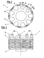
- Outwardly spooled multi-pole stators are known, formed by a substantially star-shaped stack of sheets featuring a plurality of poles extending from a tubular core.
- the stators of this type are suitable for coupling with an inner concentric armature or outer ring armature. They are common in brushless motors.
- the adjacent peripheries of the poles, or pole extensions, form substantially a cylinder with a plurality of slots parallel or oblique with respect to the axis of the stator.
- the peripheries of the poles are connected to the core by means of pole walls that define corresponding notches, accessible through the slots.
- the notches have to be filled with insulated lead wire, by creating coils spooled about the pole walls.
- winding machines exist having a winding arm, or flier, which rotates causing the wire to follow a circular trajectory and thus spooling the coil about each pole wall.
- the wire follows the circular trajectory while it is guided in the slots by means of special winding shrouds.
- the shrouds are normally of two types, usually sufficient to wind the most common outwardly spooled multi-pole stators:
- the flier at winding, rotates about the support shaft of the shroud in order to have its free end that moves in orbital position both with respect to the pole being wound and to the shroud that guides the wire in the notches.
- Every portion of wire wound about one or more poles has at least two ends.
- the ends have to be inserted into terminals.
- the terminals in turn, when the motor is assembled, are connected to the current supply circuits for operation of the motor.
- the terminals are integrated in a terminal board, which is a body of plastic material that insulates axially the stack of sheets that form the ferromagnetic core of the stator.
- the termination apparatus comprises tools like lead pulls, cutters, clamps, which move in a direction which, normally, is orthogonal to the axis of the stator.
- the termination apparatus can be arranged in the easiest way for catching the ends. Instead, when winding stators with external poles, with a flier, the position of the termination tools interferes with the movement of the flier, and they are therefore complex to arrange.
- the flier moves the wire must be blocked in the terminal, to avoid that it can move away from the terminal at winding in the first coils.
- the movement of the flier keeps the wire stretched while the termination is carried out.
- the wire can be blocked, in most of cases, at a suitable moment with a special instrument on board of the machine and that engages the terminal, approaching orthogonally to the axis of the stator.
- a further problem is that, when introducing an end of wire in a terminal, the end protrudes of a certain amount beyond the terminal, and has to be trimmed. Thus, an off-cut wire portion would fall at the base of the machine or, where possible, in a container located underneath. This has the risk that the off-cut portion can sometimes jam into the machine or remain accidentally wound in the stator, causing in both cases a serious drawback.
- Document US 4 826 092 discloses a rotor armature winding machine. It is provided with a flier and an inclined multifunctional instrument which carries out the wire termination operations of catching a wire, moving, laying around the armature terminals and cutting the wire.
- the multifunctional instrument performs the operations along and around its own inclined axis as well as in vertical direction.
- Another object of the present invention is to provide a terminating device that moves without obstructing the movement of the flier during the termination.
- a method for wire termination on outwardly spooled multi-pole stators wherein the stators are formed by a core of ferromagnetic sheets, having an axis and a plurality of poles that radially extend defining notches between them, and by a terminal board that covers in part the core and has a plurality of terminals, wherein the wire is wound about the poles distributed by a flier and guided by shrouds that move radially with respect to the stator overlapping the respective polar extension, and wherein before and/or after winding wire termination operations are provided of the wire in the terminals with the aid of the flier, the operations of terminating comprising steps of catching, moving, introducing in the terminals and cutting a portion of wire, has the characteristic that the steps of catching, moving, introducing and cutting the wire occur by means of a single multifunctional instrument having an axis parallel to the axis of the stator, capable of carrying out a plurality of movements parallel to and
- the axis of the multifunctional instrument is incident to the stator.
- the step of introducing the wire comprises, before starting winding step, a step of creating a bridge of wire between a clamp and a taker-in element, and a step of introducing the wire bridge in the terminal by translating the bridge parallel to the axis.
- the step of creating the bridge can be carried out by rotating the clamp and the taker-in element about the axis.
- the step of cutting the wire is carried out by bringing a blade parallel to the axis up to intersecting the wire, kept by a clamp.
- the step of cutting the wire being associated to a movement of folding the portion of cut wire protruding from a terminal to bend along the terminal side before the start of winding.
- the portion of cut wire bent along the terminal side advantageously, is kept pressed against the terminal at least during the first winding phases.
- the portion of cut wire is kept pressed elastically by an element associated to the shroud that extends from the shroud in a direction orthogonal to the axis.
- the step of catching the wire, when after winding a portion of wire is stretched between the flier and a spooled coil is carried out by translating a clamp parallel to the axis up to a predetermined position, opening the clamp, rotating the flier until the stretched wire portion does not intersect the predetermined position, closing the clamp.
- the steps of catching the wire and of terminating can be aided by indexing the stator about its own axis.
- a step is provided of bringing the portion of wire to the predetermined position by a protruding element that rotates coaxially to the clamp and intersects the portion of wire.
- a method for wire termination on outwardly spooled multi-pole stators wherein the stators have a core from which radially extend a plurality of pole walls with poles defining notches between them, the pole extensions having longitudinal edges, which define the slots for entering the notches, and circumferential edges that define the height of the stator, the poles having terminals, wherein the wire is wound about the pole walls by means of a flier guided by shrouds that overlap the circumferential edges of the pole and that move along a radial direction with respect to the stator for laying the wire along the pole walls, and wherein the flier carries out operations of wire termination on the wire ends in the terminals before and/or after winding, whose characteristic is that a step is provided of blocking the wire ends near to or at the terminals, the step of blocking being carried out in a direction parallel to said radial direction.
- a device for wire termination on outwardly spooled multi-pole stators, wherein the stators are formed by a core of ferromagnetic sheets, having an axis and a plurality of poles that radially extend defining notches between them, and by a terminal board that covers in part the core and has a plurality of terminals, associated to a stator winding machine comprising at least a flier and a shroud that moves radially with respect to the stator overlapping the respective polar extension.
- the device has means for terminating wire ends in the terminals with the aid of the flier and of an index motion of the stator, and has the characteristic of having an axis parallel to the axis of the stator and of being equipped with means for catching, moving, introducing in the terminals and cutting a portion of wire associated to means for their movement in a direction parallel to said axis.
- the means for introducing the wire can comprise means for creating a bridge of wire between a clamp and a taker-in element, and means for introducing in a terminal the bridge by translating the bridge parallel to the axis.
- the means for creating the bridge comprise means for rotating the clamp and the taker-in element about the axis.
- the means for cutting the wire comprise a blade sliding parallel to the axis up to intersecting the wire, kept by the clamp.
- the means for cutting the wire can be associated to a deflector movable parallel to the axis and suitable for folding the portion of cut wire protruding from a terminal bending along an end of same before the start of winding.
- such pushing means comprise an element associated to the shroud that extends from the shroud in a direction orthogonal to the axis, the pushing element being biased by a spring.
- the means for catching the wire comprise a clamp movable parallel to the axis up to a predetermined position, the clamp being formed by a first and a second gripper suitable for closing on each other with movement parallel to the axis.
- a second deflector is provided for bringing a portion of wire stretched between the flier and the stator to the predetermined position, the second deflector comprising a protruding element that rotates coaxially.
- a stator winding machine of the above type comprising a flier suitable for winding the wire about the pole walls and shrouds that approach the circumferential edges of the polar extension, overtaking them and moving along an axis that is radial with respect to the stator for spooling the wire along the pole walls, has the characteristic that blocking means are provided of the wire ends near to or at the terminals, the blocking means moving in a direction parallel to said radial axis and having an end suitable for pushing an end against the stator near to or at the terminal.
- the shroud comprises a first portion that approaches form outside the polar extension, allowing a second portion to overtake the circumferential edges of the pole and move along the radial axis, the blocking means being mounted on the first portion.
- the blocking means comprise a pin parallel to the radial axis and slidingly engaged in the first portion, being provided a resilient element opposing to the sliding of the pin in the first portion.
- an outwardly spooled multi-pole stator 1 has a core formed by a stack of ferromagnetic sheets 2, having an axis of symmetry 7 and a plurality of poles 6 having pole walls 61 that radially extend defining notches 60 between them, stack 2 is in part covered by a terminal board 3 that has a plurality of terminals 4. Terminals have a terminal slit 62 wherein a terminal of wire spooled about poles 6 has to be inserted.
- a winding step for example, is shown in figure 14 .
- Wire 15 is wound about poles 6 distributed by a rotatable arm or flier 10 having a needle end 11.
- Wire 15 slides through flier 11, while it is kept stretched and fed by means not shown, and known to a person skilled in the art.
- wire is guided by shrouds 16 that move radially with respect to stator 1 thus overlapping the respective pole 6.
- a pole 6 already wound with a coil 5 is shown on the right edge of the stator, with an end 5' that engages a terminal 4.
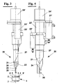
- Device 20 comprises a first deflector 21, a second deflector 22, a blade 23, and a clamp formed by a movable gripper 24 and a fixed gripper 25, the former being suitable for closing onto the latter for gripping wire 15.
- Device 20 can carry out steps of catching, moving, introducing and cutting wire 15 with movements parallel to its own axis 27, which coincides or is parallel to axis 7 of stator 1.
- the device 20 can translate along axis 27 and rotate about axis 27 owing to a motor 24'.
- Fixed gripper 25 remains integral to it, which guides other tools 21, 22, 23, 24 as hereinafter indicated. Other tools can then move parallel to axis 27, and in particular:
- the drives are not shown in detail since they comprise motors and linear actuators of known type to a man of the art.
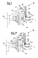
- the steps of termination are the following: before starting a winding cycle on one pole of a stator without previous windings, or on which previous winding step has already been made of a coil 5, with end 5' in a terminal 6, wire 15 is held by gripper 24-25 in a way shown in figure 5 .
- first deflector 21 ( figure 6 ) is lowered, and then the whole device 20 ( figure 7 ) is lowered up to a step of creating a bridge 15' of wire 15 ( figure 8 ) between gripper 24-25 and deflector 21. This is carried out by means of rotating device 20 about axis 27.
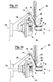
- a step follows of introducing into a terminal 4 bridge 15' of wire 15 by translating along axis 27 ( figure 9 ).
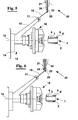
- a downwards movement of gripper 24-25 causes bending of end 5' along external wall of terminal 4, as shown in figure 10 .
- end 5' is in terminal 4, but the tension of wire 15, and a further movement of flier 10 for starting winding could cause the wire to disengage from terminal 4.
- first deflector 21 remains in lowered position, bearing the tension of wire 15.
- the remainder of device 20 has moved upwards.
- shroud 16 is approached to stator and is ready for winding.
- an end 5' of wire 15 is kept pressed against terminal 4 by a pushing element 17, associated with a spring 18, and integral to the body of shroud 16.
- first deflector 21 can rise ( figure 13 ) and device 20 can rotate returning again to the starting position.
- Pusher 17 keeps an end 5' pressed against terminal 4, so that winding can start ( figure 14 ) and during winding of the first coils, the tension of wire 15 does not pull an end 5' out from terminal 4.
- shroud 16 distributes the wire about the poles, and its reciprocation towards/away from axis of stator does not cause pusher 17 to loose contact from end 5', nor it creates interferences with the stator, owing to spring 18.
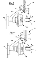
- device 20 is lowered, with gripper 24-25 open, in order to engage wire 15.
- a movement of flier 10 can make this step easier.
- second deflector 22 is lowered and ( figure 16 ) stops at the height of terminal 4.
- grippers 24,25 are lowered that cause the wire to enter the terminal ( figure 17 ), and at same time, blade 23 cuts wire between gripper 24-25 and the terminal, so that an end 5" is cut close to terminal 4 and the other cut end of wire 15 remains on gripper 24-25.
- device 20 moves up again, back to the position of figure 5 , with stator 1 spooled with one or more coils 5 about respective poles 6, as well as with ends 5' and 5'' inserted into respective terminals 4.
- shroud 16 as shown in the figures, can be replaced by a much simpler shroud, of the type formed by a single shield with central opening through which the pole of stator passes when spooling.
- pushing element 17 is equally present, arranged in the central opening of this type of shroud.
- An embodiment of the method according to the invention relates to winding an outwardly spooled multi-pole stator 41, figures 19 and 20 , that has a core formed by a stack of ferromagnetic sheets 42, an axis of symmetry 47 and a plurality of poles 46 that radially extend defining notches between them.
- the stack 42 is in part covered by a terminal board 43 that has a plurality of terminals 44.
- the terminals 44 have a terminal slit wherein an end 45' of wire 45 spooled about the poles 46 has to be inserted.
- the terminals 44 contrarily to the case of figures 1 and 2 , are arranged within the poles 46.
- a winding step for example, is shown in figure 32 .
- the wire 15 is wound about the poles 46 distributed by flier 10.
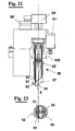
- wire termination operations are provided of the wire ends 15 into the terminals 44, with the aid of flier 10, carried out by an apparatus equipped with a terminating device 50 shown in figures 21 and 22 . Such operations, according to the invention, are described hereinafter.
- the device 50 comprises a first deflector 51, a second deflector 52, a blade 53, and a clamp formed by a movable gripper 54 and a fixed gripper 55, the latter being suitable for closing on the former for gripping wire 15.
- the device 50 can carry out the steps of catching, moving, introducing and cutting the wire 15 with movements parallel to its own axis 57, which coincides with or is parallel to axis 7 of stator 1.
- the device 50 can translate along axis 57 and rotate about axis 57 owing to a motor 50'.
- Fixed gripper 55 remains integral to it. The other tools can then move parallel to axis 57, and in particular:
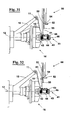
- the steps of termination are the following: before starting a winding cycle on one pole of a stator without windings, or on which have already been spooled some coils 45, with end 45' in a terminal 44, the wire 15 is held by the gripper 54-55 in the way shown in figure 23 .
- the first deflector 51 ( figure 24 ) is lowered, and then all the device 50 ( figure 25 ) is lowered up to a step of creating a bridge 15' of wire 15 between the gripper 54-55 and the deflector 51.
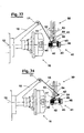
- a step follows of introduction into a terminal 44 of bridge 15' of wire 15 by translation along the axis 57 ( figure 26 ).
- the shroud withdraws, and the stator, in a way not shown, is subject to an index movement for winding a pole different from that already wound.
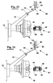
- the wire in this step, is not cut. Winding starts again, and at the end the shroud 16 withdraws again ( figure 33 ).
- the wire 15 that is stretched between the flier 10 and the stator 41, has to be cut and terminated in the respective terminal 44.
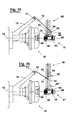
- device 50 Before this ( figure 33 ), device 50 is lowered, with gripper 54-55 open and second deflector 52 rotated about the axis 57 to the side that is oriented towards the shroud 16, in order to engage wire 15. A movement of flier 10 can make this step easier. Second deflector 52 then rotates ( figure 34 ) and stops when the wire is aligned with terminal 44 and has entered gripper 54-55.
- flier 10 is lowered that causes the wire to enter the terminal 44, and, at the same time, blade 53 cuts the wire between gripper 54-55 and terminal 44, so that an end 45'' is cut close to terminal 44 and the other cut end of wire 15 remains in gripper 54-55 ( figure 35 ).
Landscapes
- Engineering & Computer Science (AREA)
- Manufacturing & Machinery (AREA)
- Power Engineering (AREA)
- Manufacture Of Motors, Generators (AREA)
Claims (19)
- Ein Verfahren zum Abschluss eines Zuleitungsdrahts (15) auf außen bewickelten Multipolstatoren (1,41),
wobei die Statoren durch einen Kern aus ferromagnetischen Lagen (2,42), die eine Achse (7,47) und mehrere Pole (6,46) aufweisen, welche sich radial erstrecken und Ausnehmungen (60) zwischen sich definieren, und durch eine Abschlussplatte (3,43), welche teilweise den Kern abdeckt und mehrere Anschlüsse (4,44) besitzt, gebildet sind bzw. werden,
wobei der Draht (15) um die Pole herum gewickelt wird, indem er durch einen Flier (10) verteilt und durch Krägen ("shrouds") (16) geführt wird, welche sich radial bezüglich dem Stator bewegen, und so dass er die jeweilige Polerweiterung überlagert,
und wobei, vor und/oder nach dem Wickeln, Drahtabschlussoperationen der Drahtenden (5',45') in den Anschlüssen mit Hilfe des Fliers (10) vorgenommen werden, wobei die Operationen des Abschließens Schritte des Fangens, des Bewegens, des Einführens in die Anschlüsse und des Abschneidens eines Abschnitts des Drahts (15) umfassen,
dadurch gekennzeichnet, dass die Schritte des Fangens, des Bewegens, des Einführens und des Abschneidens des Drahts mittels eines einzelnen multifunktionalen Instruments (20,50) erfolgen, das eine Achse (27,57) besitzt, welche parallel zu der Achse (7,47) des Stators (1,41) ist, und das mehrere Bewegungen parallel zu und/oder Drehungen um die Achse (27,57) des multifunktionalen Instruments (20,50) herum ausführen kann. - Verfahren gemäß Anspruch 1, wobei die Achse (27,57) des multifunktionalen Instruments (20,50) auf den Stator (1,41) trifft.
- Verfahren gemäß Anspruch 1, wobei der Schritt des Einführens des Drahts (15), vor dem Starten eines wicklungsschritts, einen Schritt des Erzeugens einer Brücke (15') aus Draht zwischen einer Klemme (24,25,54,55) und einem Aufnehmerelement (21,51), sowie einen Schritt des Einführens der Drahtbrücke (15') in den Anschluss (4,44) durch Versetzen der Brücke parallel zu der Achse (27,57) aufweist.
- Verfahren gemäß Anspruch 3, wobei der Schritt des Erzeugens der Brücke (15') durch Drehen der Klemme (24,25) und des Aufnehmerelements (21) um die Achse (27) ausgeführt werden kann.
- Verfahren gemäß Anspruch 1, wobei der Schritt des Abschneidens des Drahts (15) ausgeführt wird, indem eine Klinge (23,53) parallel zu der Achse (27) nach oben in Überschneidung mit dem Draht, welcher durch eine Klemme (24,25) gehalten wird, gebracht wird.
- Verfahren gemäß Anspruch 1, wobei der Schritt des Abschneidens des Drahts einer Bewegung des Faltens des Abschnitts (5',45') des abgeschnittenen Drahts, welcher von einem Anschluss (4) vorsteht, zugeordnet ist, um diesen entlang einer Abschlussseite vor dem Start des wickelns abzubiegen.
- Verfahren gemäß Anspruch 6, wobei der Abschnitt (5') des abgeschnittenen Drahts, der entlang der Anschlussseite abgebogen ist, gegen den Anschluss (4) zumindest während einer ersten Phase des Wickelns der Pole (6) gedrückt gehalten wird, um den Draht in dem Anschluss zu sichern.
- Verfahren gemäß Anspruch 7, wobei der Anschluss (4) umfangsmäßig an der Polerweiterung angeordnet ist, wobei der Abschnitt des abgeschnittenen Drahts (5') durch ein Element (17), das dem Kragen (16) zu geordnet ist, elastisch gedrückt gehalten wird, und dass sich das Element (17) von dem Kragen in einer Richtung orthogonal zu der Achse (27) erstreckt.
- Verfahren gemäß Anspruch 1, wobei der Schritt des Fangens des Drahts (15), wenn nach dem Wickeln ein Abschnitt (15) des Drahts zwischen dem Flier (10) und einer aufgewickelten Spule (5) gespannt wird, durch Versetzen einer Klemme (24,25,54,55) parallel zu der Achse (7,27) bis zu einer vorbestimmten Position, durch Öffnen der Klemme (24,25,54,55) durch Drehen des Fliers bis der gespannte Drahtabschnitt (15) die vorbestimmte Position nicht schneidet, und durch Schließen der Klemme (24,25,54,55) ausgeführt wird.
- Verfahren gemäß Anspruch 1, wobei ein Schritt vorgesehen ist, um den Abschnitt (15) des Drahts zu der vorbestimmten Position, durch ein vorstehendes Element (22), welches sich koaxial mit der Klemme (24,25) dreht und mit dem Abschnitt des Drahts in Eingriff gelangt, zu bringen.
- Vorrichtung zum Drahtabschluss an außen bewickelten Multipolstatoren,
wobei die Statoren (1,41) durch einen Kern aus ferromagnetischen Lagen (2,42), der eine Achse (7,47) und mehrere Pole (6,46) aufweist, die sich radial erstrecken und Ausnehmungen (60) zwischen sich definieren, und durch eine Abschlussplatte (3,43), welche teilweise den Kern abdeckt und mehrere Anschlüsse (4,44) besitzt, gebildet sind,
wobei einer Statorwicklungsmaschine zugeordnet zumindest ein Flier (10) und ein Kragen (16) vorgesehen ist, der sich radial bezüglich dem Stator bewegt, und die jeweilige Polerweiterung überlagert,
wobei Mittel zum Abschluss von Drahtenden (5',45') in den Anschlüssen mit Hilfe der Flier vorgesehen sind, und die Mittel zum Abschluss Mittel zum Fangen, zum Bewegen, zum Einführen in die Anschlüsse und zum Abschneiden eines Abschnitts des Drahts (15) aufweisen,
dadurch gekennzeichnet, dass die Mittel zum Fangen, Bewegen, Einführen und Abschneiden des Drahts in einem einzelnen multifunktionalen Instrument (20,50) integriert sind, das eine Achse (27,57), parallel zu der Achse (7,47) des Stators (1,41) aufweist und mehrere Bewegungen parallel zu und/oder Drehungen um die Achse (27,57) des multifunktionalen Instruments (20,50) ausführen kann. - Vorrichtung gemäß Anspruch 11, wobei die Mittel zum Einführen des Drahts (15) Mittel zum Erzeugen einer Brücke (15') aus Draht zwischen einer Klemme (24,25,54,55) und einem Aufnehmerelement (21,51), und Mittel zum Einführen der Brücke in einen Anschluss (4,44) durch versetzen der Brücke parallel zu der Achse (27,57) aufweisen.
- Vorrichtung gemäß Anspruch 12, wobei die Mittel zum Erzeugen der Brücke (15') Mittel (24') zum Drehen der Klemme (24,25) und des Aufnehmerelements (21) um die Achse (27,57) herum aufweisen.
- Vorrichtung gemäß Anspruch 11, wobei das Mittel zum Abschneiden des Drahts (15) eine Klinge (23,53) aufweist, welche parallel zu der Achse (27,57) bis zur Überschneidung mit dem Draht, welcher durch die Klemme (24,25,54,55) gehalten ist, gleitet.
- Vorrichtung gemäß Anspruch 11, wobei die Mittel zum Abschneiden des Drahts (15) einem Deflektor zugeordnet sind, welcher parallel zu der Achse bewegbar ist und zum Falten des Abschnitts des abgeschnittenen Drahts (5',45') geeignet sind, der von einem Anschluss (4,44) vorsteht, um diesem vor dem Start des Aufwickelns entlang der Anschlussseite abzubiegen.
- Vorrichtung gemäß Anspruch 15, wobei, wenn der Anschluss (4,44) umfangsmäßig an bzw. auf dem Pol angeordnet ist, Mittel (17) vorgesehen sind, um den Abschnitt des abgeschnittenen Drahts (5',45'), der entlang der Anschlussseite abgebogen ist, zumindest während einer ersten Phase des wickelns der Pole (6) zu drücken, um den Draht in dem Anschluss zu sichern.
- Vorrichtung gemäß Anspruch 16, wobei die Drückmittel (17) ein Element aufweisen, das dem Kragen (16) zugeordnet ist und sich von dem Kragen in einer Richtung orthogonal zu der Achse (27) erstreckt, wobei das Drückelement durch eine Feder vorbelastet ist.
- Vorrichtung gemäß Anspruch 11, wobei die Mittel zum Fangen des Drahts eine Klemme (24,25,54,55) umfassen, die parallel zu der Achse (27,57) bis zu einer bestimmten Position bewegbar ist, wobei die Klemme durch einen ersten und einen zweiten Greifer gebildet ist, welche zum Schließen aufeinander mit der Bewegung parallel zu der Achse geeignet sind.
- Vorrichtung gemäß Anspruch 18, wobei ein zweiter Deflektor (52) vorgesehen ist, um einen Abschnitt des Drahts (15), der zwischen dem Flier (10) und dem Stator (1,41) gespannt ist, zu der vorbestimmten Position zu bringen, wobei der zweite Deflektor ein vorstehendes Element aufweist, das sich koaxial mit der Klemme dreht und mit dem Abschnitt des Drahts in Eingriff ist bzw. gelangt.
Priority Applications (10)
| Application Number | Priority Date | Filing Date | Title |
|---|---|---|---|
| DE60233303T DE60233303D1 (de) | 2002-04-10 | 2002-04-10 | Verfahren und Vorrichtung zum Wicklungsabschluss bei außenbewickelten Multipolstatoren |
| SI200230856T SI1353435T1 (sl) | 2002-04-10 | 2002-04-10 | Postopek in naprava za napeljevanje žic na navzven navite več-polne statorje |
| AT02425221T ATE439696T1 (de) | 2002-04-10 | 2002-04-10 | VERFAHREN UND VORRICHTUNG ZUM WICKLUNGSABSCHLUSS BEI AUßENBEWICKELTEN MULTIPOLSTATOREN |
| EP02425221A EP1353435B1 (de) | 2002-04-10 | 2002-04-10 | Verfahren und Vorrichtung zum Wicklungsabschluss bei außenbewickelten Multipolstatoren |
| DK02425221T DK1353435T3 (da) | 2002-04-10 | 2002-04-10 | Fremgangsmåde og apparat til ledningsterminering på udvendigt viklede statorer med flere poler |
| ES02425221T ES2332211T3 (es) | 2002-04-10 | 2002-04-10 | Metodo y aparato para la terminacion de hilos en estatores multipolares bobinados hacia fuera. |
| US10/406,471 US20030192981A1 (en) | 2002-04-10 | 2003-04-03 | Method and apparatus for wire termination on outwardly spooled multi-pole stators |
| US11/078,459 US20050156076A1 (en) | 2002-04-10 | 2005-03-11 | Method and apparatus for wire termination on outwardly spooled multi-pole stators |
| US11/787,191 US20080277521A1 (en) | 2002-04-10 | 2007-04-12 | Method and apparatus for wire termination on outwardly spooled multi-pole stators |
| US12/889,626 US8230585B2 (en) | 2002-04-10 | 2010-09-24 | Method and apparatus for wire termination on outwardly spooled multi-pole stators |
Applications Claiming Priority (1)
| Application Number | Priority Date | Filing Date | Title |
|---|---|---|---|
| EP02425221A EP1353435B1 (de) | 2002-04-10 | 2002-04-10 | Verfahren und Vorrichtung zum Wicklungsabschluss bei außenbewickelten Multipolstatoren |
Publications (2)
| Publication Number | Publication Date |
|---|---|
| EP1353435A1 EP1353435A1 (de) | 2003-10-15 |
| EP1353435B1 true EP1353435B1 (de) | 2009-08-12 |
Family
ID=28051900
Family Applications (1)
| Application Number | Title | Priority Date | Filing Date |
|---|---|---|---|
| EP02425221A Expired - Lifetime EP1353435B1 (de) | 2002-04-10 | 2002-04-10 | Verfahren und Vorrichtung zum Wicklungsabschluss bei außenbewickelten Multipolstatoren |
Country Status (7)
| Country | Link |
|---|---|
| US (4) | US20030192981A1 (de) |
| EP (1) | EP1353435B1 (de) |
| AT (1) | ATE439696T1 (de) |
| DE (1) | DE60233303D1 (de) |
| DK (1) | DK1353435T3 (de) |
| ES (1) | ES2332211T3 (de) |
| SI (1) | SI1353435T1 (de) |
Families Citing this family (9)
| Publication number | Priority date | Publication date | Assignee | Title |
|---|---|---|---|---|
| IT1394587B1 (it) | 2009-04-29 | 2012-07-05 | Atop Spa | Apparecchiatura e metodo per avvolgere e terminare nuclei per macchine dinamo elettriche |
| FR2984627B1 (fr) | 2011-12-20 | 2016-06-24 | Valeo Equip Electr Moteur | Rotor a poles saillants comportant une piece de guidage de fils de bobinage, piece de guidage de fils de bobinage et procede de bobinage associes |
| CN104247230B (zh) * | 2012-02-20 | 2017-04-12 | 路易斯·芬克尔 | 用于定子绕组端接的设备和方法 |
| CN102751826B (zh) * | 2012-07-12 | 2014-03-05 | 临海市劳尔机械有限公司 | 一种定子自动多极数绕线机 |
| ITPI20130031A1 (it) | 2013-04-19 | 2014-10-20 | Atop Spa | Linee di produzione per produrre componenti di nucleo di una macchina dinamo-elettrica |
| CN110171744B (zh) * | 2019-05-27 | 2024-09-24 | 上海托展智能科技股份有限公司 | 一种定子上下料装置及方法 |
| CN111262398B (zh) * | 2020-03-27 | 2025-06-06 | 惠州龙德科技股份有限公司 | 一种电机引线处理设备 |
| DE102022201866A1 (de) | 2022-02-23 | 2023-08-24 | Robert Bosch Gesellschaft mit beschränkter Haftung | Wickelvorrichtung zum Herstellen von Wicklungen in elektrischen Maschinen |
| CN116251912B (zh) * | 2023-03-17 | 2025-08-29 | 深圳市合利士智能装备有限公司 | 定子扁线切平机及其切平方法 |
Family Cites Families (9)
| Publication number | Priority date | Publication date | Assignee | Title |
|---|---|---|---|---|
| US3628229A (en) * | 1969-04-01 | 1971-12-21 | Globe Tool Eng Co | Automatic armature winding machine |
| IT1215177B (it) * | 1986-08-04 | 1990-01-31 | Magneti Marelli Spa | Macchina automatica per la formazione degli avvolgimenti di indotto nelle cave di rotori di macchine dinamoelettriche |
| JPS6380743A (ja) * | 1986-09-22 | 1988-04-11 | Odawara Eng:Kk | 電機子の巻線装置 |
| US4830297A (en) * | 1987-11-25 | 1989-05-16 | Statomat-Globe, Inc. | Winding form assembly |
| US5413403A (en) * | 1993-08-09 | 1995-05-09 | Globe Products Inc. | Lead pull assembly |
| EP0897608A4 (de) * | 1996-05-08 | 1999-08-04 | Globe Products Inc | Verfahren und gerät zur statorwicklung |
| US6532645B1 (en) * | 1999-11-03 | 2003-03-18 | Axis Usa, Inc. | Wire winding apparatus for dynamo-electric components |
| EP1281232A1 (de) * | 2000-04-13 | 2003-02-05 | Globe Products Inc. | Statorwicklungs- und spulenanschlussabschlussverfahren und -vorrichtung |
| JP4718693B2 (ja) * | 2001-02-09 | 2011-07-06 | 株式会社小田原エンジニアリング | 電機子巻線機におけるカッタ装置 |
-
2002
- 2002-04-10 DK DK02425221T patent/DK1353435T3/da active
- 2002-04-10 ES ES02425221T patent/ES2332211T3/es not_active Expired - Lifetime
- 2002-04-10 DE DE60233303T patent/DE60233303D1/de not_active Expired - Lifetime
- 2002-04-10 SI SI200230856T patent/SI1353435T1/sl unknown
- 2002-04-10 AT AT02425221T patent/ATE439696T1/de not_active IP Right Cessation
- 2002-04-10 EP EP02425221A patent/EP1353435B1/de not_active Expired - Lifetime
-
2003
- 2003-04-03 US US10/406,471 patent/US20030192981A1/en not_active Abandoned
-
2005
- 2005-03-11 US US11/078,459 patent/US20050156076A1/en not_active Abandoned
-
2007
- 2007-04-12 US US11/787,191 patent/US20080277521A1/en not_active Abandoned
-
2010
- 2010-09-24 US US12/889,626 patent/US8230585B2/en not_active Expired - Fee Related
Also Published As
| Publication number | Publication date |
|---|---|
| US20030192981A1 (en) | 2003-10-16 |
| US8230585B2 (en) | 2012-07-31 |
| EP1353435A1 (de) | 2003-10-15 |
| ATE439696T1 (de) | 2009-08-15 |
| US20050156076A1 (en) | 2005-07-21 |
| US20080277521A1 (en) | 2008-11-13 |
| SI1353435T1 (sl) | 2010-01-29 |
| DE60233303D1 (de) | 2009-09-24 |
| ES2332211T3 (es) | 2010-01-29 |
| US20110131795A1 (en) | 2011-06-09 |
| DK1353435T3 (da) | 2009-12-07 |
Similar Documents
| Publication | Publication Date | Title |
|---|---|---|
| US8230585B2 (en) | Method and apparatus for wire termination on outwardly spooled multi-pole stators | |
| EP1997213B1 (de) | Vorrichtungen und verfahren zum wickeln von drahtspulen von dynamoelektrischen maschinenkernen | |
| KR101967607B1 (ko) | 전자 정류식 직류 모터 | |
| EP1324471B1 (de) | Verfahren und Anordnung zur Drahtführung von mit Flyerflügel gewickelten Mehrpolstatoren | |
| EP2425520A1 (de) | Vorrichtung zum wickeln und abschliessen von dynamoelektrischen maschinenkernen | |
| JP6259285B2 (ja) | 集中巻ステータの巻線挿入方法および巻線挿入機 | |
| EP4490836A1 (de) | Anordnung zur bildung von wicklungen für elektrische maschinen | |
| US5493770A (en) | Dynamo-electric machine armature winding methods and apparatus | |
| GB929839A (en) | Stator winding machine | |
| JP2000014095A (ja) | 歯形状固定子,そのコイル組付方法及びコイル組付装置 | |
| EP1387468A1 (de) | Verfahren und Vorrichtung zum Wicklen mehrpolige elektrische Maschine mit Hakentwicklungsanschlüssen | |
| EP0387411B1 (de) | Verfahren und Vorrichtung zur Herstellung von Ständern mit Wicklungsanschlüssen an beiden Enden | |
| EP1387469B1 (de) | Verfahren und Vorrichtung zum Wickeln einer mehrpoligen elektrischen Maschine mit Hakenwicklungsanschlüssen | |
| US4153985A (en) | Method of looping armature coil leads about commutator tangs | |
| KR101864075B1 (ko) | Bldc 모터용 고정자에 코일을 권선하는 방법 | |
| EP1282216A2 (de) | Verfahren zum Wickeln eines Drehfeldmaschinenankers | |
| US6036135A (en) | Winding of coils into axial slots in rotationally symmetric bodies of electrical devices | |
| JP5991275B2 (ja) | 巻線部品の結線方法および結線装置 | |
| KR101880851B1 (ko) | Bldc 모터용 고정자의 코일 인서팅 장치 | |
| KR100201929B1 (ko) | 모터 권선장치 및 방법 | |
| WO2025237899A1 (en) | Method and device for the insertion of shaped conductor elements into slots of a ferromagnetic core | |
| JPH08223874A (ja) | 電機子の巻線装置 | |
| CN119174097A (zh) | 用于高密度铜填充内齿电动马达定子的针缠绕及其方法 | |
| JP2003032976A (ja) | 巻線方法、巻線機及び多極電機子 | |
| JPH11346449A (ja) | コイル巻線方法及びその装置 |
Legal Events
| Date | Code | Title | Description |
|---|---|---|---|
| PUAI | Public reference made under article 153(3) epc to a published international application that has entered the european phase |
Free format text: ORIGINAL CODE: 0009012 |
|
| AK | Designated contracting states |
Kind code of ref document: A1 Designated state(s): AT BE CH CY DE DK ES FI FR GB GR IE IT LI LU MC NL PT SE TR |
|
| AX | Request for extension of the european patent |
Extension state: AL LT LV MK RO SI |
|
| 17P | Request for examination filed |
Effective date: 20040405 |
|
| AKX | Designation fees paid |
Designated state(s): AT BE CH CY DE DK ES FI FR GB GR IE IT LI LU MC NL PT SE TR |
|
| AXX | Extension fees paid |
Extension state: SI Payment date: 20040405 |
|
| 17Q | First examination report despatched |
Effective date: 20070418 |
|
| GRAP | Despatch of communication of intention to grant a patent |
Free format text: ORIGINAL CODE: EPIDOSNIGR1 |
|
| GRAS | Grant fee paid |
Free format text: ORIGINAL CODE: EPIDOSNIGR3 |
|
| GRAA | (expected) grant |
Free format text: ORIGINAL CODE: 0009210 |
|
| AK | Designated contracting states |
Kind code of ref document: B1 Designated state(s): AT BE CH CY DE DK ES FI FR GB GR IE IT LI LU MC NL PT SE TR |
|
| AX | Request for extension of the european patent |
Extension state: SI |
|
| REG | Reference to a national code |
Ref country code: GB Ref legal event code: FG4D |
|
| REG | Reference to a national code |
Ref country code: CH Ref legal event code: EP |
|
| REG | Reference to a national code |
Ref country code: IE Ref legal event code: FG4D |
|
| REF | Corresponds to: |
Ref document number: 60233303 Country of ref document: DE Date of ref document: 20090924 Kind code of ref document: P |
|
| REG | Reference to a national code |
Ref country code: DK Ref legal event code: T3 |
|
| REG | Reference to a national code |
Ref country code: CH Ref legal event code: NV Representative=s name: KELLER & PARTNER PATENTANWAELTE AG |
|
| PG25 | Lapsed in a contracting state [announced via postgrant information from national office to epo] |
Ref country code: FI Free format text: LAPSE BECAUSE OF FAILURE TO SUBMIT A TRANSLATION OF THE DESCRIPTION OR TO PAY THE FEE WITHIN THE PRESCRIBED TIME-LIMIT Effective date: 20090812 Ref country code: AT Free format text: LAPSE BECAUSE OF FAILURE TO SUBMIT A TRANSLATION OF THE DESCRIPTION OR TO PAY THE FEE WITHIN THE PRESCRIBED TIME-LIMIT Effective date: 20090812 Ref country code: SE Free format text: LAPSE BECAUSE OF FAILURE TO SUBMIT A TRANSLATION OF THE DESCRIPTION OR TO PAY THE FEE WITHIN THE PRESCRIBED TIME-LIMIT Effective date: 20090812 |
|
| REG | Reference to a national code |
Ref country code: ES Ref legal event code: FG2A Ref document number: 2332211 Country of ref document: ES Kind code of ref document: T3 |
|
| NLV1 | Nl: lapsed or annulled due to failure to fulfill the requirements of art. 29p and 29m of the patents act | ||
| PG25 | Lapsed in a contracting state [announced via postgrant information from national office to epo] |
Ref country code: NL Free format text: LAPSE BECAUSE OF FAILURE TO SUBMIT A TRANSLATION OF THE DESCRIPTION OR TO PAY THE FEE WITHIN THE PRESCRIBED TIME-LIMIT Effective date: 20090812 |
|
| PG25 | Lapsed in a contracting state [announced via postgrant information from national office to epo] |
Ref country code: PT Free format text: LAPSE BECAUSE OF FAILURE TO SUBMIT A TRANSLATION OF THE DESCRIPTION OR TO PAY THE FEE WITHIN THE PRESCRIBED TIME-LIMIT Effective date: 20091212 |
|
| PLBE | No opposition filed within time limit |
Free format text: ORIGINAL CODE: 0009261 |
|
| STAA | Information on the status of an ep patent application or granted ep patent |
Free format text: STATUS: NO OPPOSITION FILED WITHIN TIME LIMIT |
|
| PG25 | Lapsed in a contracting state [announced via postgrant information from national office to epo] |
Ref country code: BE Free format text: LAPSE BECAUSE OF FAILURE TO SUBMIT A TRANSLATION OF THE DESCRIPTION OR TO PAY THE FEE WITHIN THE PRESCRIBED TIME-LIMIT Effective date: 20090812 |
|
| PGFP | Annual fee paid to national office [announced via postgrant information from national office to epo] |
Ref country code: GB Payment date: 20100324 Year of fee payment: 9 |
|
| 26N | No opposition filed |
Effective date: 20100517 |
|
| PGFP | Annual fee paid to national office [announced via postgrant information from national office to epo] |
Ref country code: ES Payment date: 20100423 Year of fee payment: 9 |
|
| PG25 | Lapsed in a contracting state [announced via postgrant information from national office to epo] |
Ref country code: GR Free format text: LAPSE BECAUSE OF FAILURE TO SUBMIT A TRANSLATION OF THE DESCRIPTION OR TO PAY THE FEE WITHIN THE PRESCRIBED TIME-LIMIT Effective date: 20091113 |
|
| PG25 | Lapsed in a contracting state [announced via postgrant information from national office to epo] |
Ref country code: MC Free format text: LAPSE BECAUSE OF NON-PAYMENT OF DUE FEES Effective date: 20100430 |
|
| PG25 | Lapsed in a contracting state [announced via postgrant information from national office to epo] |
Ref country code: IE Free format text: LAPSE BECAUSE OF NON-PAYMENT OF DUE FEES Effective date: 20100410 |
|
| GBPC | Gb: european patent ceased through non-payment of renewal fee |
Effective date: 20110410 |
|
| PG25 | Lapsed in a contracting state [announced via postgrant information from national office to epo] |
Ref country code: GB Free format text: LAPSE BECAUSE OF NON-PAYMENT OF DUE FEES Effective date: 20110410 |
|
| REG | Reference to a national code |
Ref country code: ES Ref legal event code: FD2A Effective date: 20120524 |
|
| PG25 | Lapsed in a contracting state [announced via postgrant information from national office to epo] |
Ref country code: ES Free format text: LAPSE BECAUSE OF NON-PAYMENT OF DUE FEES Effective date: 20110411 |
|
| PG25 | Lapsed in a contracting state [announced via postgrant information from national office to epo] |
Ref country code: CY Free format text: LAPSE BECAUSE OF FAILURE TO SUBMIT A TRANSLATION OF THE DESCRIPTION OR TO PAY THE FEE WITHIN THE PRESCRIBED TIME-LIMIT Effective date: 20090812 |
|
| PG25 | Lapsed in a contracting state [announced via postgrant information from national office to epo] |
Ref country code: LU Free format text: LAPSE BECAUSE OF NON-PAYMENT OF DUE FEES Effective date: 20100410 |
|
| REG | Reference to a national code |
Ref country code: CH Ref legal event code: PCAR Free format text: NEW ADDRESS: EIGERSTRASSE 2 POSTFACH, 3000 BERN 14 (CH) |
|
| REG | Reference to a national code |
Ref country code: FR Ref legal event code: PLFP Year of fee payment: 14 |
|
| REG | Reference to a national code |
Ref country code: FR Ref legal event code: PLFP Year of fee payment: 15 |
|
| REG | Reference to a national code |
Ref country code: FR Ref legal event code: PLFP Year of fee payment: 16 |
|
| REG | Reference to a national code |
Ref country code: FR Ref legal event code: PLFP Year of fee payment: 17 |
|
| REG | Reference to a national code |
Ref country code: CH Ref legal event code: PFA Owner name: ATOP S.P.A., IT Free format text: FORMER OWNER: ATOP S.P.A., IT |
|
| PGFP | Annual fee paid to national office [announced via postgrant information from national office to epo] |
Ref country code: TR Payment date: 20210331 Year of fee payment: 20 |
|
| PGFP | Annual fee paid to national office [announced via postgrant information from national office to epo] |
Ref country code: IT Payment date: 20210430 Year of fee payment: 20 Ref country code: FR Payment date: 20210421 Year of fee payment: 20 Ref country code: DE Payment date: 20210421 Year of fee payment: 20 |
|
| PGFP | Annual fee paid to national office [announced via postgrant information from national office to epo] |
Ref country code: DK Payment date: 20210420 Year of fee payment: 20 Ref country code: CH Payment date: 20210422 Year of fee payment: 20 |
|
| REG | Reference to a national code |
Ref country code: DE Ref legal event code: R071 Ref document number: 60233303 Country of ref document: DE |
|
| REG | Reference to a national code |
Ref country code: DK Ref legal event code: EUP Expiry date: 20220410 |
|
| REG | Reference to a national code |
Ref country code: CH Ref legal event code: PL |