EP1353040B1 - Turbine mit verschiebbaren Leitschaufeln - Google Patents
Turbine mit verschiebbaren Leitschaufeln Download PDFInfo
- Publication number
- EP1353040B1 EP1353040B1 EP03252067A EP03252067A EP1353040B1 EP 1353040 B1 EP1353040 B1 EP 1353040B1 EP 03252067 A EP03252067 A EP 03252067A EP 03252067 A EP03252067 A EP 03252067A EP 1353040 B1 EP1353040 B1 EP 1353040B1
- Authority
- EP
- European Patent Office
- Prior art keywords
- vanes
- width
- variable geometry
- height
- inlet passageway
- Prior art date
- Legal status (The legal status is an assumption and is not a legal conclusion. Google has not performed a legal analysis and makes no representation as to the accuracy of the status listed.)
- Expired - Lifetime
Links
- 230000007704 transition Effects 0.000 claims description 2
- 230000004048 modification Effects 0.000 description 7
- 238000012986 modification Methods 0.000 description 7
- 238000002485 combustion reaction Methods 0.000 description 6
- 230000000694 effects Effects 0.000 description 5
- 238000001595 flow curve Methods 0.000 description 2
- 239000000446 fuel Substances 0.000 description 2
- 230000007246 mechanism Effects 0.000 description 2
- 230000009467 reduction Effects 0.000 description 2
- 230000009747 swallowing Effects 0.000 description 2
- 230000002411 adverse Effects 0.000 description 1
- 230000007423 decrease Effects 0.000 description 1
- 230000003247 decreasing effect Effects 0.000 description 1
- 230000001419 dependent effect Effects 0.000 description 1
- 238000007789 sealing Methods 0.000 description 1
- 238000004513 sizing Methods 0.000 description 1
Images

Classifications
-
- F—MECHANICAL ENGINEERING; LIGHTING; HEATING; WEAPONS; BLASTING
- F02—COMBUSTION ENGINES; HOT-GAS OR COMBUSTION-PRODUCT ENGINE PLANTS
- F02B—INTERNAL-COMBUSTION PISTON ENGINES; COMBUSTION ENGINES IN GENERAL
- F02B37/00—Engines characterised by provision of pumps driven at least for part of the time by exhaust
- F02B37/12—Control of the pumps
- F02B37/24—Control of the pumps by using pumps or turbines with adjustable guide vanes
-
- F—MECHANICAL ENGINEERING; LIGHTING; HEATING; WEAPONS; BLASTING
- F02—COMBUSTION ENGINES; HOT-GAS OR COMBUSTION-PRODUCT ENGINE PLANTS
- F02B—INTERNAL-COMBUSTION PISTON ENGINES; COMBUSTION ENGINES IN GENERAL
- F02B37/00—Engines characterised by provision of pumps driven at least for part of the time by exhaust
- F02B37/12—Control of the pumps
- F02B37/22—Control of the pumps by varying cross-section of exhaust passages or air passages, e.g. by throttling turbine inlets or outlets or by varying effective number of guide conduits
-
- F—MECHANICAL ENGINEERING; LIGHTING; HEATING; WEAPONS; BLASTING
- F01—MACHINES OR ENGINES IN GENERAL; ENGINE PLANTS IN GENERAL; STEAM ENGINES
- F01D—NON-POSITIVE DISPLACEMENT MACHINES OR ENGINES, e.g. STEAM TURBINES
- F01D17/00—Regulating or controlling by varying flow
- F01D17/10—Final actuators
- F01D17/12—Final actuators arranged in stator parts
- F01D17/14—Final actuators arranged in stator parts varying effective cross-sectional area of nozzles or guide conduits
- F01D17/141—Final actuators arranged in stator parts varying effective cross-sectional area of nozzles or guide conduits by means of shiftable members or valves obturating part of the flow path
- F01D17/143—Final actuators arranged in stator parts varying effective cross-sectional area of nozzles or guide conduits by means of shiftable members or valves obturating part of the flow path the shiftable member being a wall, or part thereof of a radial diffuser
-
- F—MECHANICAL ENGINEERING; LIGHTING; HEATING; WEAPONS; BLASTING
- F01—MACHINES OR ENGINES IN GENERAL; ENGINE PLANTS IN GENERAL; STEAM ENGINES
- F01D—NON-POSITIVE DISPLACEMENT MACHINES OR ENGINES, e.g. STEAM TURBINES
- F01D17/00—Regulating or controlling by varying flow
- F01D17/10—Final actuators
- F01D17/12—Final actuators arranged in stator parts
- F01D17/14—Final actuators arranged in stator parts varying effective cross-sectional area of nozzles or guide conduits
- F01D17/16—Final actuators arranged in stator parts varying effective cross-sectional area of nozzles or guide conduits by means of nozzle vanes
- F01D17/167—Final actuators arranged in stator parts varying effective cross-sectional area of nozzles or guide conduits by means of nozzle vanes of vanes moving in translation
-
- Y—GENERAL TAGGING OF NEW TECHNOLOGICAL DEVELOPMENTS; GENERAL TAGGING OF CROSS-SECTIONAL TECHNOLOGIES SPANNING OVER SEVERAL SECTIONS OF THE IPC; TECHNICAL SUBJECTS COVERED BY FORMER USPC CROSS-REFERENCE ART COLLECTIONS [XRACs] AND DIGESTS
- Y02—TECHNOLOGIES OR APPLICATIONS FOR MITIGATION OR ADAPTATION AGAINST CLIMATE CHANGE
- Y02T—CLIMATE CHANGE MITIGATION TECHNOLOGIES RELATED TO TRANSPORTATION
- Y02T10/00—Road transport of goods or passengers
- Y02T10/10—Internal combustion engine [ICE] based vehicles
- Y02T10/12—Improving ICE efficiencies
Definitions
- the present invention relates to a variable geometry turbine, and in particular to a turbine of a type suitable for use in a turbocharger for an internal combustion engine. More particularly still, the invention provides advantages in turbochargers intended for internal combustion engines which have an exhaust gas recirculation system.
- Variable geometry turbines are well known and generally comprise a turbine chamber within which a turbine wheel is mounted, an annular inlet passageway arranged around the turbine chamber, an inlet chamber arranged around the inlet passageway, and an outlet passageway extending from the turbine chamber, the passageways and chambers communicating such that pressurised gas admitted to the inlet chamber flows through the inlet passageway to the outlet passageway via the turbine chamber.
- one wall of the inlet passageway is defined by a moveable wall member, generally termed "nozzle ring”, the position of which relative to a facing wall of the inlet passageway is adjustable to control the width of the inlet passageway.
- the inlet passageway width and thus the geometry of the turbine is varied so that as the volume of gas flowing through the turbine decreases the inlet passageway width is also decreased to maintain gas velocity and hence turbine efficiency.
- nozzle vanes in the inlet passageway so as to deflect gas flowing through the inlet passageway towards the direction of rotation of the turbine wheel.
- Nozzle vanes are provided in both fixed and variable geometry turbines. In the latter case the provision of vanes complicates the variable geometry structure, in particular to ensure that the vanes always extend across the full width of the inlet passageway.
- variable geometry structures are described for example in US patent number 4,292,807, and British patent specification numbers GB-A-1138941 and GB-A-2044860. These specifications describe various arrangements in which the nozzle vanes extend from a moveable nozzle ring into slots provided on the facing wall of the inlet passageway. This arrangement also ensures that the vanes always extend across the full width of the passageway, even when the passageway is fully open.
- turbine efficiency begins to drop off as the vanes are retracted from the inlet passageway, efficiency may still be greater than that achieved at the low flow range of the turbine. Essentially, therefore, controlled retraction of the vanes enables modification of the turbines characteristic efficiency verses flow curve so that for a given flow range the mean turbine efficiency may be increased by avoiding the need to operate the turbine in the less efficient low flow region.
- nozzle vanes extend from a moveable nozzle ring which defines one wall of the turbine inlet passageway into slots defined in an opposing fixed wall of the turbine inlet passageway, and wherein the nozzle ring can be over-opened beyond the full width of the passageway.
- the nozzle vanes have a cut-out at their radially inner edge and towards the end of the vanes remote from the nozzle ring. This cut-out vane which has a reduced chord, i.e. its effective width opposing gas flow from the inlet chamber to the turbine chamber.
- variable geometry turbine designs can be problematical when the turbine is intended for use with an internal combustion engine having an exhaust gas recirculation (EGR) system.
- EGR exhaust gas recirculation
- a portion of the exhaust gas taken from the exhaust manifold is reintroduced into the inlet manifold of the engine for further combustion with a view to reducing engine emissions.
- boost pressure at the inlet manifold can often exceed the exhaust gas pressure at the exhaust manifold making the reintroduction of exhaust gas to the inlet manifold problematical, for instance, requiring dedicated EGR pumps etc.
- a variable geometry turbine comprising a turbine wheel having radial blades and supported in a housing for rotation about an axis, an annular inlet passageway extending radially inwards towards the turbine wheel, the inlet passageway being defined between an annular wall of a moveable wall member and a facing wall of the housing, the moveable wall member being moveable relative to the housing to vary the width of the inlet passageway, an annular array of vanes extending across the inlet passageway, the vanes having leading and trailing edges, a width defined between the leading and trailing edges and a height extending generally parallel to the axis of the turbine wheel, wherein the height varies across the width of the vanes from a maximum to a minimum, the minimum height being less than the axial width of the turbine blade tips, characterised in that the minimum height of the vanes is greater than the minimum width of the inlet passageway.
- the minimum height is defined at the trailing edge of the vanes.
- the maximum height of the vanes is greater than the maximum width of the inlet passageway.
- the difference between the minimum height and the maximum height is no less than the axial width of the turbine blade tips.
- the vanes may have a maximum width portion and a reduced width portion and a sharp transition in vane height between the two.
- the maximum vane height will generally be defined along the leading edge of the vanes.
- the vane height may be substantially constant across part of the width of the vane adjacent the leading edge and then reduces to the minimum height adjacent the trailing edge.
- the vane height may also be substantially constant across a part of the width of the vane adjacent the trailing edge.
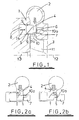
- FIG. 1 this is a schematic radial section through part of a known variable geometry turbine which comprises a turbine housing 1 defining a volute or inlet chamber 2 to which gas from an internal combustion engine (not shown) is delivered.
- the gas flows from the inlet chamber 2 to an axial outlet passageway 3 via an annular inlet passageway 4 defined on one side by the radial face of a nozzle ring 5 and on the other by an annular shroud plate 6 which covers the opening of an annular recess 7 defined in the opposing wall of the housing 1.
- the nozzle ring 5 is slidably mounted within an annular cavity 8 provided in the turbine housing 1, and is sealed with respect thereto by sealing rings 9.
- the nozzle ring 5 supports an array of nozzle vanes 10 which extend from the face of the nozzle ring 5 across the inlet passageway 4.
- the height of the vanes i.e. the extent to which the vanes 10 extend axially from the face of the nozzle ring 5 is such that the vanes extend right across the inlet passageway 4, through suitably configured slots in the shroud plate 6, and into the recess 7.
- Each vane 10 has a width, or chord length, defined as the distance between its leading and trailing edge (i.e. radially outer and inner edges). From Figure 1 it will be seen that each blade is cut away at its end to define a portion 10a which has a reduced height and chord length.
- gas flowing from the inlet chamber 2 to the outlet passageway 3 passes over a turbine wheel 11 which rotates about an axis 12 and thereby applies torque to a turbocharger shaft 13 which drives a compressor wheel (not shown).
- the speed of the turbine wheel 11 is dependent upon the velocity of the gas passing through the annular inlet passageway 4.
- the gas velocity is a function of the width of the inlet passageway 4, which can be adjusted by controlling the axial position of the nozzle ring 5 (i.e. by moving it back and forth as indicated by the arrow 14). Movement of the nozzle ring 5 may be controlled by any suitable actuation means.
- the nozzle ring 5 may be mounted on axially extending pins (not shown) the position of which is controlled by a stirrup member (not shown) linked to a pneumatically operated actuator (not shown). Since the actuator system may take a variety of conventional forms no particular actuator mechanism is illustrated.
- FIG 1 the nozzle ring is shown in a "closed" position at which the width of the inlet passageway 4 is reduced to a minimum. In this position it will be seen that the ends of the nozzle vanes 10 abut the housing 1 within the recess 7, the reduced chordal length portion 10a of the vanes 10 being entirely received within the recess 7.
- Figures 2a and 2b show the nozzle ring 5 in mid flow and maximum flow positions respectively.
- the nozzle ring 5 is withdrawn part way into the cavity 8 so that the face of the nozzle ring 5 is flush with the wall of the housing and the inlet passageway 4 is at its maximum width.
- the vane height should be equal or greater than the width of the turbine wheel blade tips 11 a.
- the vanes 10 are configured so that the minimum height of the blade is sufficient to extend across the inlet passageway 4 when the inlet passageway is fully open as shown in Figure 3a.
- the reduced chordal length portion 10a of the blade 10 is received within the recess 7.
- the swallowing capacity of the turbine can however be increased by further withdrawing the nozzle ring 5 into the cavity 8 so that the reduced chordal width portion 10a of the vanes is retracted at least partially from the recess 7 to lie within the inlet passageway 4.
- the total vane area obstructing gas flow through the inlet passageway 4 is thereby reduced.
- FIG 3 A typical efficiency verses gas flow characteristic for a turbine such as illustrated in Figure 1 is shown in Figure 3. This shows that the efficiency is good (although relatively low) at low flow rates when the nozzle ring 5 is around the closed position, and increases to a peak around the mid flow rate position. The efficiency then drops off as the reduced chordal portion of the nozzle vane 10 is brought into the inlet passageway, reaching a minimum efficiency at the maximum flow position illustrated in Figure 2b.
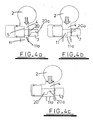
- Figures 4a to 4b illustrate a modification to the vane profile illustrated in Figures 1 and 2 to modify the turbine efficiency characteristic in accordance with the present invention.
- the size of the cut-out at the end of the vanes 20 is increased so that the minimum height of each vane along its trailing edge, is less than the width of the tip of the 11a of the turbine blades. The effect of this is that the reduced chordal length portion 20a of the vanes 20 extends into the inlet passageway 4 even when the inlet passageway 4 is not fully open.
- the reduced vane height has no effect when the nozzle ring is in the closed position, since the minimum height of the vane is sufficient to extend across the minimum of the inlet aperture 4.
- the reduced chordal length portion 20a of each vane 20 is retracted from the recess 7 before the nozzle ring 5 reaches the mid flow position.
- the reduced chordal length region of 20a of the vanes 20 already lies at least partially in the inlet passageway 4.
- the present invention has particular advantages when applied to turbines of turbochargers intended for internal combustion engines having EGR systems as it enables the engine intake and exhaust manifold conditions to be optimised for exhaust gas recirculation, reducing emissions whilst at the same time minimising the air/fuel ratio for better fuel consumption. This is achieved by a reduction in turbine efficiency which is carefully controlled by a simple nozzle ring modification without requiring any additional parts or geometry control mechanisms.
- the size and profile of the vane cut out may vary widely depending on the desired turbine characteristic.
- the invention is applicable to variable geometry turbines in which the vane is fixed in position with a moveable nozzle ring which slides over the vanes.
- the cut out can be positioned so that as the nozzle ring retracts to open the inlet passageway it reveals an increasing amount of the reduced chord length portion of the vanes.
Landscapes
- Engineering & Computer Science (AREA)
- Mechanical Engineering (AREA)
- General Engineering & Computer Science (AREA)
- Chemical & Material Sciences (AREA)
- Combustion & Propulsion (AREA)
- Supercharger (AREA)
- Control Of Turbines (AREA)
Claims (12)
- Turbine mit veränderlicher Geometrie, die Folgendes umfasst: ein Turbinenlaufrad (11), das Radialschaufeln hat und in einem Gehäuse (1) zum Drehen um eine Achse (12) getragen wird, einen ringförmigen Einlassdurchgang (4), der sich in Radialrichtung nach innen zum Turbinenlaufrad (11) hin erstreckt, wobei der Einlassdurchgang (4) zwischen einer ringförmigen Wand eines beweglichen Wandelements (5) und einer Stirnwand des Gehäuses (1) definiert wird, wobei das bewegliche Wandelement (5) im Verhältnis zum Gehäuse (1) bewegt werden kann, um die Breite des Einlassdurchgangs (4) zu verändern, eine ringförmige Anordnung von Leitschaufeln (20), die sich über den Einlassdurchgang (4) erstrecken, wobei die Leitschaufeln (20) vordere und hintere Kanten, eine zwischen den vorderen und den hinteren Kanten definierte Breite und eine Höhe, die sich allgemein parallel zur Achse (12) des Turbinenlaufrades (11) erstreckt, haben, wobei sich die Höhe über die Breite der Leitschaufeln von einem Maximum zu einem Minimum verändert, wobei die minimale Höhe geringer ist als die Breite der Turbinenschaufelspitzen (11a) in Axialrichtung, dadurch gekennzeichnet, dass die minimale Höhe der Leitschaufeln (20) größer ist als die minimale Breite des Einlassdurchgangs (4).
- Turbine mit veränderlicher Geometrie nach Anspruch 1, wobei die minimale Höhe an der hinteren Kante der Leitschaufeln (20) definiert wird.
- Turbine mit veränderlicher Geometrie nach einem der vorhergehenden Ansprüche, wobei die maximale Höhe der Leitschaufeln (20) größer ist als die maximale Breite des Einlassdurchgangs (4).
- Turbine mit veränderlicher Geometrie nach einem der vorhergehenden Ansprüche, wobei der Unterschied zwischen der minimalen Höhe und der maximalen Höhe nicht geringer ist als die Breite der Turbinenschaufelspitzen (11a) in Axialrichtung.
- Turbine mit veränderlicher Geometrie nach einem der vorhergehenden Ansprüche, wobei die Leitschaufeln (20) einen Abschnitt mit maximaler Breite und einen Abschnitt (20a) mit verringerter Breite und zwischen den zwei einen scharfen Übergang in der Leitschaufelhöhe haben.
- Turbine mit veränderlicher Geometrie nach einem der vorhergehenden Ansprüche, wobei die maximale Höhe längs der vorderen Kante der Leitschaufeln (20) definiert wird.
- Turbine mit veränderlicher Geometrie nach Anspruch 6, wobei die Leitschaufelhöhe über einen Teil der Breite der Leitschaufel (20) angrenzend an die vordere Kante wesentlich gleichbleibend ist und sich danach bis zur minimalen Höhe angrenzend an die hintere Kante verringert.
- Turbine mit veränderlicher Geometrie nach Anspruch 7, wobei die Leitschaufelhöhe über einen Teil der Breite der Leitschaufel (20) angrenzend an die hintere Kante wesentlich gleichbleibend ist.
- Turbine mit veränderlicher Geometrie nach Anspruch 8, wobei die Leitschaufeln (20) durch das bewegliche Wandelement (5) getragen werden.
- Turbine mit veränderlicher Geometrie nach Anspruch 9, wobei die Stirnwand des Turbinengehäuses (1) mit einer ringförmigen Aussparung (7) versehen ist, um die Leitschaufeln (20) aufzunehmen, wenn das bewegliche Wandelement (5) zur Stirnwand hin bewegt wird.
- Turbine mit veränderlicher Geometrie nach Anspruch 10, wobei die ringförmige Aussparung (7) durch eine Abdeckung (6) abgedeckt wird, die mit Schlitzen zum Aufnehmen der Leitschaufeln (20) versehen ist.
- Turbine mit veränderlicher Geometrie nach einem der vorhergehenden Ansprüche, wobei das bewegliche Wandelement (5) in einem innerhalb des Gehäuses (1) bereitgestellten ringförmigen Hohlraum (8) angebracht ist, wobei die maximale Einlassbreite definiert wird, wenn die ringförmige Wand des beweglichen Wandelements (5) bündig mit der Öffnung des Hohlraums (8) liegt, und wobei das Wandelement (5) in den Hohlraum (8) eingezogen werden kann.
Applications Claiming Priority (2)
| Application Number | Priority Date | Filing Date | Title |
|---|---|---|---|
| US117872 | 2002-04-08 | ||
| US10/117,872 US6652224B2 (en) | 2002-04-08 | 2002-04-08 | Variable geometry turbine |
Publications (3)
| Publication Number | Publication Date |
|---|---|
| EP1353040A2 EP1353040A2 (de) | 2003-10-15 |
| EP1353040A3 EP1353040A3 (de) | 2005-05-11 |
| EP1353040B1 true EP1353040B1 (de) | 2007-02-21 |
Family
ID=28453957
Family Applications (1)
| Application Number | Title | Priority Date | Filing Date |
|---|---|---|---|
| EP03252067A Expired - Lifetime EP1353040B1 (de) | 2002-04-08 | 2003-04-01 | Turbine mit verschiebbaren Leitschaufeln |
Country Status (6)
| Country | Link |
|---|---|
| US (2) | US6652224B2 (de) |
| EP (1) | EP1353040B1 (de) |
| JP (1) | JP4256196B2 (de) |
| KR (1) | KR20030081059A (de) |
| CN (1) | CN1324222C (de) |
| DE (1) | DE60311908T2 (de) |
Cited By (2)
| Publication number | Priority date | Publication date | Assignee | Title |
|---|---|---|---|---|
| DE102009012132A1 (de) | 2009-03-06 | 2010-09-09 | Daimler Ag | Abgasturbine mit einer verstellbaren Leitschaufel |
| WO2011141425A1 (de) * | 2010-05-12 | 2011-11-17 | Siemens Aktiengesellschaft | Einstellbarer radialverdichterdiffusor |
Families Citing this family (27)
| Publication number | Priority date | Publication date | Assignee | Title |
|---|---|---|---|---|
| US6652224B2 (en) * | 2002-04-08 | 2003-11-25 | Holset Engineering Company Ltd. | Variable geometry turbine |
| US7150151B2 (en) * | 2002-11-19 | 2006-12-19 | Cummins Inc. | Method of controlling the exhaust gas temperature for after-treatment systems on a diesel engine using a variable geometry turbine |
| US7207176B2 (en) | 2002-11-19 | 2007-04-24 | Cummins Inc. | Method of controlling the exhaust gas temperature for after-treatment systems on a diesel engine using a variable geometry turbine |
| WO2005106212A1 (en) * | 2004-05-03 | 2005-11-10 | Honeywell International Inc. | Center housing of a turbine for a turbocharger and method of manufacturing the same |
| US7165936B2 (en) * | 2004-08-16 | 2007-01-23 | Honeywell International, Inc. | Adjustable flow turbine nozzle |
| KR101070903B1 (ko) * | 2004-08-19 | 2011-10-06 | 삼성테크윈 주식회사 | 가변 베인형 터빈 |
| DE102005027080A1 (de) | 2005-06-11 | 2006-12-14 | Daimlerchrysler Ag | Abgasturbine in einem Abgasturbolader |
| WO2007058649A1 (en) * | 2005-11-16 | 2007-05-24 | Honeywell International, Inc. | Turbocharger with stepped two-stage vane nozzle |
| GB0805519D0 (en) * | 2008-03-27 | 2008-04-30 | Cummins Turbo Tech Ltd | Variable geometry turbine |
| GB2462115A (en) * | 2008-07-25 | 2010-01-27 | Cummins Turbo Tech Ltd | Variable geometry turbine |
| EP2351920B1 (de) | 2008-11-05 | 2016-04-13 | IHI Corporation | Turbolader |
| EP2423485B1 (de) * | 2009-04-24 | 2016-12-14 | Toyota Jidosha Kabushiki Kaisha | Aufladesystem für verbrennungsmotoren |
| JP5582145B2 (ja) * | 2009-09-08 | 2014-09-03 | 株式会社Ihi | 高速応答性を実現するロケットエンジンシステム |
| CN102472298A (zh) * | 2010-03-18 | 2012-05-23 | 丰田自动车株式会社 | 离心压缩机及涡轮增压器 |
| GB201015679D0 (en) * | 2010-09-20 | 2010-10-27 | Cummins Ltd | Variable geometry turbine |
| DE102010051359A1 (de) * | 2010-11-13 | 2012-05-16 | Daimler Ag | Einsatzelement für eine Turbine eines Abgasturboladers, Abgasturbolader sowie Turbine für einen Abgasturbolader |
| CN102269018A (zh) * | 2011-08-23 | 2011-12-07 | 常州环能涡轮动力有限公司 | 可变截面增压器的喷嘴组件 |
| DE102011120553A1 (de) * | 2011-12-08 | 2013-06-13 | Daimler Ag | Turbine für einen Abgasturbolader |
| US10543973B2 (en) * | 2012-02-08 | 2020-01-28 | Brent Eugene Cunningham | System and method for maintaining a temperature within a cooler |
| CN102661179B (zh) * | 2012-05-29 | 2015-05-20 | 湖南天雁机械有限责任公司 | 可变喷嘴环定位结构 |
| CN104295325B (zh) * | 2014-09-16 | 2016-02-03 | 萍乡德博科技股份有限公司 | 一种涡轮增压器用可变截面喷嘴环 |
| DE102015212808A1 (de) * | 2015-07-08 | 2017-01-12 | Continental Automotive Gmbh | Abgasturbolader mit verstellbarer Turbinengeometrie |
| US9932888B2 (en) | 2016-03-24 | 2018-04-03 | Borgwarner Inc. | Variable geometry turbocharger |
| US10570759B2 (en) * | 2017-07-10 | 2020-02-25 | GM Global Technology Operations LLC | Variable-geometry turbine housing intake channel for an exhaust driven turbocharger |
| CN108930586A (zh) * | 2018-06-29 | 2018-12-04 | 大连海事大学 | 一种变几何涡轮及喷嘴环装置 |
| DE112019007228B4 (de) * | 2019-04-19 | 2025-12-11 | Mitsubishi Heavy Industries Engine & Turbocharger, Ltd. | Turbine mit variabler geometrie und lader |
| US11371374B2 (en) * | 2020-07-22 | 2022-06-28 | Raytheon Technologies Corporation | Seal runner flow damper |
Family Cites Families (19)
| Publication number | Priority date | Publication date | Assignee | Title |
|---|---|---|---|---|
| US3221767A (en) | 1965-12-07 | Metering valve with viscosity gompensating adjustment | ||
| GB1138941A (en) | 1965-01-15 | 1969-01-01 | Stuart Swinford Wilson | Improvements in and relating to radial flow turbines |
| US3384338A (en) | 1965-04-06 | 1968-05-21 | North American Rockwell | Variable orifice device |
| US3511470A (en) | 1968-02-12 | 1970-05-12 | Beckett Harcum Co | Needle valve |
| CH638867A5 (de) | 1979-03-16 | 1983-10-14 | Bbc Brown Boveri & Cie | Turbolader mit einer einrichtung zur regelung des schluckvermoegens der turbine. |
| US4292807A (en) | 1979-05-02 | 1981-10-06 | United Technologies Corporation | Variable geometry turbosupercharger system for internal combustion engine |
| JPS57180559A (en) | 1981-03-31 | 1982-11-06 | Xerox Corp | Sorter for collating sheet |
| DE3278214D1 (en) | 1981-11-14 | 1988-04-14 | Holset Engineering Co | A variable inlet area turbine |
| GB2218744B (en) | 1988-05-17 | 1992-03-18 | Holset Engineering Co | Variable geometry turbine |
| ES2082673B1 (es) | 1992-02-26 | 1997-02-01 | Badain S L | Valvula de regulacion para grandes saltos de presion. |
| DE4232400C1 (de) * | 1992-03-14 | 1993-08-19 | Mercedes-Benz Aktiengesellschaft, 7000 Stuttgart, De | |
| DE4228565A1 (de) | 1992-08-27 | 1994-03-10 | Danfoss As | Ventil mit Voreinstellung |
| US5410882A (en) | 1993-08-26 | 1995-05-02 | Jacobs Brake Technology Corporation | Compression release engine braking systems |
| SE505572C2 (sv) | 1995-12-19 | 1997-09-15 | Volvo Ab | Ventil för variering av avgasmottrycket i en förbränningsmotor |
| GB2319811A (en) * | 1996-10-03 | 1998-06-03 | Holset Engineering Co | A variable geometry turbocharger for an internal combustion engine |
| GB2326198A (en) * | 1997-06-10 | 1998-12-16 | Holset Engineering Co | Variable geometry turbine |
| US6089019A (en) | 1999-01-15 | 2000-07-18 | Borgwarner Inc. | Turbocharger and EGR system |
| AU2000267060A1 (en) * | 2000-07-19 | 2002-01-30 | Alliedsignal Turbo S.A. | Sliding vane turbocharger with graduated vanes |
| US6652224B2 (en) * | 2002-04-08 | 2003-11-25 | Holset Engineering Company Ltd. | Variable geometry turbine |
-
2002
- 2002-04-08 US US10/117,872 patent/US6652224B2/en not_active Expired - Lifetime
-
2003
- 2003-04-01 EP EP03252067A patent/EP1353040B1/de not_active Expired - Lifetime
- 2003-04-01 DE DE60311908T patent/DE60311908T2/de not_active Expired - Lifetime
- 2003-04-07 KR KR10-2003-0021753A patent/KR20030081059A/ko not_active Abandoned
- 2003-04-08 JP JP2003104238A patent/JP4256196B2/ja not_active Expired - Fee Related
- 2003-04-08 CN CNB03136098XA patent/CN1324222C/zh not_active Expired - Fee Related
- 2003-11-11 US US10/705,737 patent/US7108481B2/en not_active Expired - Lifetime
Non-Patent Citations (1)
| Title |
|---|
| None * |
Cited By (2)
| Publication number | Priority date | Publication date | Assignee | Title |
|---|---|---|---|---|
| DE102009012132A1 (de) | 2009-03-06 | 2010-09-09 | Daimler Ag | Abgasturbine mit einer verstellbaren Leitschaufel |
| WO2011141425A1 (de) * | 2010-05-12 | 2011-11-17 | Siemens Aktiengesellschaft | Einstellbarer radialverdichterdiffusor |
Also Published As
| Publication number | Publication date |
|---|---|
| CN1324222C (zh) | 2007-07-04 |
| US7108481B2 (en) | 2006-09-19 |
| DE60311908D1 (de) | 2007-04-05 |
| JP4256196B2 (ja) | 2009-04-22 |
| US20050005604A1 (en) | 2005-01-13 |
| KR20030081059A (ko) | 2003-10-17 |
| US6652224B2 (en) | 2003-11-25 |
| EP1353040A3 (de) | 2005-05-11 |
| DE60311908T2 (de) | 2007-11-08 |
| US20030190231A1 (en) | 2003-10-09 |
| JP2003301726A (ja) | 2003-10-24 |
| EP1353040A2 (de) | 2003-10-15 |
| CN1455077A (zh) | 2003-11-12 |
Similar Documents
| Publication | Publication Date | Title |
|---|---|---|
| EP1353040B1 (de) | Turbine mit verschiebbaren Leitschaufeln | |
| EP1584796B1 (de) | Turbine mit variabler Geometrie | |
| EP2025897B1 (de) | Turbinenanordnung mit halbgeteilter Düse und Kolben mit halben Kragen | |
| US8172516B2 (en) | Variable geometry turbine | |
| US8721268B2 (en) | Turbomachine | |
| US6932565B2 (en) | Turbine | |
| JP2005299660A5 (de) | ||
| WO2004022922A1 (en) | Improved cambered vane for use in turbochargers | |
| EP2105583B1 (de) | Turbolader mit Gleitkolben und Leitschaufeln mit Dichtungsdämmen | |
| US8221059B2 (en) | Variable geometry turbine | |
| EP1700005B1 (de) | Verstellbare düseneinrichtung für einen turbolader | |
| EP2037084A1 (de) | Turbolader mit Schwenkkolben mit übergelagert befestigten und beweglichen Lamellen | |
| EP1866534B1 (de) | Turbolader mit variabler strömung | |
| US8197195B2 (en) | Turbocharger with stepped two-stage vane nozzle | |
| GB2458191A (en) | Variable geometry turbine for a turbocharger |
Legal Events
| Date | Code | Title | Description |
|---|---|---|---|
| PUAI | Public reference made under article 153(3) epc to a published international application that has entered the european phase |
Free format text: ORIGINAL CODE: 0009012 |
|
| AK | Designated contracting states |
Kind code of ref document: A2 Designated state(s): AT BE BG CH CY CZ DE DK EE ES FI FR GB GR HU IE IT LI LU MC NL PT SE SI SK TR |
|
| AX | Request for extension of the european patent |
Extension state: AL LT LV MK RO |
|
| PUAL | Search report despatched |
Free format text: ORIGINAL CODE: 0009013 |
|
| AK | Designated contracting states |
Kind code of ref document: A3 Designated state(s): AT BE BG CH CY CZ DE DK EE ES FI FR GB GR HU IE IT LI LU MC NL PT SE SI SK TR |
|
| AX | Request for extension of the european patent |
Extension state: AL LT LV MK RO |
|
| 17P | Request for examination filed |
Effective date: 20050630 |
|
| AKX | Designation fees paid |
Designated state(s): DE FR GB |
|
| GRAP | Despatch of communication of intention to grant a patent |
Free format text: ORIGINAL CODE: EPIDOSNIGR1 |
|
| GRAS | Grant fee paid |
Free format text: ORIGINAL CODE: EPIDOSNIGR3 |
|
| GRAA | (expected) grant |
Free format text: ORIGINAL CODE: 0009210 |
|
| AK | Designated contracting states |
Kind code of ref document: B1 Designated state(s): DE FR GB |
|
| REG | Reference to a national code |
Ref country code: GB Ref legal event code: FG4D |
|
| RIN1 | Information on inventor provided before grant (corrected) |
Inventor name: PARKER, JOHN Inventor name: MALLOY, JOHN |
|
| REF | Corresponds to: |
Ref document number: 60311908 Country of ref document: DE Date of ref document: 20070405 Kind code of ref document: P |
|
| REG | Reference to a national code |
Ref country code: GB Ref legal event code: 711B |
|
| ET | Fr: translation filed | ||
| REG | Reference to a national code |
Ref country code: GB Ref legal event code: 711G |
|
| PLBE | No opposition filed within time limit |
Free format text: ORIGINAL CODE: 0009261 |
|
| STAA | Information on the status of an ep patent application or granted ep patent |
Free format text: STATUS: NO OPPOSITION FILED WITHIN TIME LIMIT |
|
| 26N | No opposition filed |
Effective date: 20071122 |
|
| REG | Reference to a national code |
Ref country code: FR Ref legal event code: PLFP Year of fee payment: 14 |
|
| REG | Reference to a national code |
Ref country code: FR Ref legal event code: PLFP Year of fee payment: 15 |
|
| REG | Reference to a national code |
Ref country code: FR Ref legal event code: PLFP Year of fee payment: 16 |
|
| PGFP | Annual fee paid to national office [announced via postgrant information from national office to epo] |
Ref country code: FR Payment date: 20200427 Year of fee payment: 18 Ref country code: DE Payment date: 20200429 Year of fee payment: 18 |
|
| PGFP | Annual fee paid to national office [announced via postgrant information from national office to epo] |
Ref country code: GB Payment date: 20210427 Year of fee payment: 19 |
|
| REG | Reference to a national code |
Ref country code: DE Ref legal event code: R119 Ref document number: 60311908 Country of ref document: DE |
|
| PG25 | Lapsed in a contracting state [announced via postgrant information from national office to epo] |
Ref country code: DE Free format text: LAPSE BECAUSE OF NON-PAYMENT OF DUE FEES Effective date: 20211103 Ref country code: FR Free format text: LAPSE BECAUSE OF NON-PAYMENT OF DUE FEES Effective date: 20210430 |
|
| GBPC | Gb: european patent ceased through non-payment of renewal fee |
Effective date: 20220401 |
|
| PG25 | Lapsed in a contracting state [announced via postgrant information from national office to epo] |
Ref country code: GB Free format text: LAPSE BECAUSE OF NON-PAYMENT OF DUE FEES Effective date: 20220401 |