EP1353040B1 - Variable geometry turbine - Google Patents
Variable geometry turbine Download PDFInfo
- Publication number
- EP1353040B1 EP1353040B1 EP03252067A EP03252067A EP1353040B1 EP 1353040 B1 EP1353040 B1 EP 1353040B1 EP 03252067 A EP03252067 A EP 03252067A EP 03252067 A EP03252067 A EP 03252067A EP 1353040 B1 EP1353040 B1 EP 1353040B1
- Authority
- EP
- European Patent Office
- Prior art keywords
- vanes
- width
- variable geometry
- height
- inlet passageway
- Prior art date
- Legal status (The legal status is an assumption and is not a legal conclusion. Google has not performed a legal analysis and makes no representation as to the accuracy of the status listed.)
- Expired - Fee Related
Links
Images

Classifications
-
- F—MECHANICAL ENGINEERING; LIGHTING; HEATING; WEAPONS; BLASTING
- F02—COMBUSTION ENGINES; HOT-GAS OR COMBUSTION-PRODUCT ENGINE PLANTS
- F02B—INTERNAL-COMBUSTION PISTON ENGINES; COMBUSTION ENGINES IN GENERAL
- F02B37/00—Engines characterised by provision of pumps driven at least for part of the time by exhaust
- F02B37/12—Control of the pumps
- F02B37/24—Control of the pumps by using pumps or turbines with adjustable guide vanes
-
- F—MECHANICAL ENGINEERING; LIGHTING; HEATING; WEAPONS; BLASTING
- F02—COMBUSTION ENGINES; HOT-GAS OR COMBUSTION-PRODUCT ENGINE PLANTS
- F02B—INTERNAL-COMBUSTION PISTON ENGINES; COMBUSTION ENGINES IN GENERAL
- F02B37/00—Engines characterised by provision of pumps driven at least for part of the time by exhaust
- F02B37/12—Control of the pumps
- F02B37/22—Control of the pumps by varying cross-section of exhaust passages or air passages, e.g. by throttling turbine inlets or outlets or by varying effective number of guide conduits
-
- F—MECHANICAL ENGINEERING; LIGHTING; HEATING; WEAPONS; BLASTING
- F01—MACHINES OR ENGINES IN GENERAL; ENGINE PLANTS IN GENERAL; STEAM ENGINES
- F01D—NON-POSITIVE DISPLACEMENT MACHINES OR ENGINES, e.g. STEAM TURBINES
- F01D17/00—Regulating or controlling by varying flow
- F01D17/10—Final actuators
- F01D17/12—Final actuators arranged in stator parts
- F01D17/14—Final actuators arranged in stator parts varying effective cross-sectional area of nozzles or guide conduits
- F01D17/141—Final actuators arranged in stator parts varying effective cross-sectional area of nozzles or guide conduits by means of shiftable members or valves obturating part of the flow path
- F01D17/143—Final actuators arranged in stator parts varying effective cross-sectional area of nozzles or guide conduits by means of shiftable members or valves obturating part of the flow path the shiftable member being a wall, or part thereof of a radial diffuser
-
- F—MECHANICAL ENGINEERING; LIGHTING; HEATING; WEAPONS; BLASTING
- F01—MACHINES OR ENGINES IN GENERAL; ENGINE PLANTS IN GENERAL; STEAM ENGINES
- F01D—NON-POSITIVE DISPLACEMENT MACHINES OR ENGINES, e.g. STEAM TURBINES
- F01D17/00—Regulating or controlling by varying flow
- F01D17/10—Final actuators
- F01D17/12—Final actuators arranged in stator parts
- F01D17/14—Final actuators arranged in stator parts varying effective cross-sectional area of nozzles or guide conduits
- F01D17/16—Final actuators arranged in stator parts varying effective cross-sectional area of nozzles or guide conduits by means of nozzle vanes
- F01D17/167—Final actuators arranged in stator parts varying effective cross-sectional area of nozzles or guide conduits by means of nozzle vanes of vanes moving in translation
-
- Y—GENERAL TAGGING OF NEW TECHNOLOGICAL DEVELOPMENTS; GENERAL TAGGING OF CROSS-SECTIONAL TECHNOLOGIES SPANNING OVER SEVERAL SECTIONS OF THE IPC; TECHNICAL SUBJECTS COVERED BY FORMER USPC CROSS-REFERENCE ART COLLECTIONS [XRACs] AND DIGESTS
- Y02—TECHNOLOGIES OR APPLICATIONS FOR MITIGATION OR ADAPTATION AGAINST CLIMATE CHANGE
- Y02T—CLIMATE CHANGE MITIGATION TECHNOLOGIES RELATED TO TRANSPORTATION
- Y02T10/00—Road transport of goods or passengers
- Y02T10/10—Internal combustion engine [ICE] based vehicles
- Y02T10/12—Improving ICE efficiencies
Landscapes
- Engineering & Computer Science (AREA)
- Mechanical Engineering (AREA)
- General Engineering & Computer Science (AREA)
- Chemical & Material Sciences (AREA)
- Combustion & Propulsion (AREA)
- Supercharger (AREA)
- Control Of Turbines (AREA)
Description
- The present invention relates to a variable geometry turbine, and in particular to a turbine of a type suitable for use in a turbocharger for an internal combustion engine. More particularly still, the invention provides advantages in turbochargers intended for internal combustion engines which have an exhaust gas recirculation system.
- Variable geometry turbines are well known and generally comprise a turbine chamber within which a turbine wheel is mounted, an annular inlet passageway arranged around the turbine chamber, an inlet chamber arranged around the inlet passageway, and an outlet passageway extending from the turbine chamber, the passageways and chambers communicating such that pressurised gas admitted to the inlet chamber flows through the inlet passageway to the outlet passageway via the turbine chamber. In one common type of variable geometry turbine, one wall of the inlet passageway is defined by a moveable wall member, generally termed "nozzle ring", the position of which relative to a facing wall of the inlet passageway is adjustable to control the width of the inlet passageway. The inlet passageway width and thus the geometry of the turbine is varied so that as the volume of gas flowing through the turbine decreases the inlet passageway width is also decreased to maintain gas velocity and hence turbine efficiency.
- It is also well known to improve turbine efficiency by providing vanes, referred to as nozzle vanes, in the inlet passageway so as to deflect gas flowing through the inlet passageway towards the direction of rotation of the turbine wheel. Nozzle vanes are provided in both fixed and variable geometry turbines. In the latter case the provision of vanes complicates the variable geometry structure, in particular to ensure that the vanes always extend across the full width of the inlet passageway.
- U.S. Patent 4,499,732, for instance, describes a variable geometry arrangement in which the vanes are fixed in position but extend through slots in a moveable nozzle ring. Thus, as the nozzle ring moves to control the width of the inlet the vanes will always extend across the full width.
- Other variable geometry structures are described for example in US patent number 4,292,807, and British patent specification numbers GB-A-1138941 and GB-A-2044860. These specifications describe various arrangements in which the nozzle vanes extend from a moveable nozzle ring into slots provided on the facing wall of the inlet passageway. This arrangement also ensures that the vanes always extend across the full width of the passageway, even when the passageway is fully open.
- Although the provision of nozzle vanes optimises turbine efficiency, the vanes have a disadvantage of reducing the effective area of the turbine inlet so that the maximum gas flow rate through the turbine is less than would be possible if the vanes were not present. US patent number 4,973,223 describes a variable geometry turbine in which the nozzle ring can be "over-opened", i.e. withdrawn beyond the nominal full width of the inlet passageway, and in doing so retract the vanes at least partially from the inlet passageway. Efficiency of the turbine drops as the vanes are retracted but the increase in maximum flow rate enables a wider range of engine speeds to be matched by the turbine. Although turbine efficiency begins to drop off as the vanes are retracted from the inlet passageway, efficiency may still be greater than that achieved at the low flow range of the turbine. Essentially, therefore, controlled retraction of the vanes enables modification of the turbines characteristic efficiency verses flow curve so that for a given flow range the mean turbine efficiency may be increased by avoiding the need to operate the turbine in the less efficient low flow region.
- It is also known to achieve the same effect in a simpler way, by modifying the profile of the nozzle vanes. The present applicant produces a variable geometry turbine in which nozzle vanes extend from a moveable nozzle ring which defines one wall of the turbine inlet passageway into slots defined in an opposing fixed wall of the turbine inlet passageway, and wherein the nozzle ring can be over-opened beyond the full width of the passageway. The nozzle vanes have a cut-out at their radially inner edge and towards the end of the vanes remote from the nozzle ring. This cut-out vane which has a reduced chord, i.e. its effective width opposing gas flow from the inlet chamber to the turbine chamber. When the nozzle ring is in an open position with the inlet passageway fully opened, the reduced chord portion of the vanes extend through the slots. However, as the nozzle ring is over-opened the reduced chord region is retracted from the inlet passageway side wall so that the total effective vane area extending across the inlet passageway is reduced increasing the swallowing capacity of the turbine. By ensuring that the reduced chord region of the each vane is hidden when the inlet passageway is fully open peak turbine efficiency is not adversely affected.
- Although good turbine efficiency is clearly desirable, conventional variable geometry turbine designs can be problematical when the turbine is intended for use with an internal combustion engine having an exhaust gas recirculation (EGR) system. In an EGR system a portion of the exhaust gas taken from the exhaust manifold is reintroduced into the inlet manifold of the engine for further combustion with a view to reducing engine emissions. With modern highly efficient variable geometry turbine designs the boost pressure at the inlet manifold can often exceed the exhaust gas pressure at the exhaust manifold making the reintroduction of exhaust gas to the inlet manifold problematical, for instance, requiring dedicated EGR pumps etc.
- An example of a turbocharger having the features of the preamble of claim 1 is disclosed in WO 02/06636.
- It is an object of the present invention to obviate or mitigate the above disadvantage.
- According to the present invention there is provided a variable geometry turbine comprising a turbine wheel having radial blades and supported in a housing for rotation about an axis, an annular inlet passageway extending radially inwards towards the turbine wheel, the inlet passageway being defined between an annular wall of a moveable wall member and a facing wall of the housing, the moveable wall member being moveable relative to the housing to vary the width of the inlet passageway, an annular array of vanes extending across the inlet passageway, the vanes having leading and trailing edges, a width defined between the leading and trailing edges and a height extending generally parallel to the axis of the turbine wheel, wherein the height varies across the width of the vanes from a maximum to a minimum, the minimum height being less than the axial width of the turbine blade tips, characterised in that the minimum height of the vanes is greater than the minimum width of the inlet passageway.
- Preferably the minimum height is defined at the trailing edge of the vanes.
- Preferably the maximum height of the vanes is greater than the maximum width of the inlet passageway.
- Preferably the difference between the minimum height and the maximum height is no less than the axial width of the turbine blade tips.
- The vanes may have a maximum width portion and a reduced width portion and a sharp transition in vane height between the two.
- The maximum vane height will generally be defined along the leading edge of the vanes. For instance the vane height may be substantially constant across part of the width of the vane adjacent the leading edge and then reduces to the minimum height adjacent the trailing edge. The vane height may also be substantially constant across a part of the width of the vane adjacent the trailing edge.
- Further preferred and advantageous features of the invention will be apparent from the following description.
- A specific embodiment of the present invention will now be described, by way of example only, with reference to the accompanying drawings, in which:
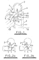
- Figure 1 is a schematic illustration of part of a known variable geometry turbine;
- Figures 2a and 2b illustrate movement of the nozzle ring of the turbine of Figure 1;
- Figure 3 is a graph illustrating the turbine efficiency verses gas flow characteristic of the turbine of Figure 1;
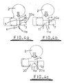
- Figures 4a to 4c illustrate a modification of the turbine of Figure 1 in accordance with the present invention; and
- Figure 5 is a graph illustrating the effect of the modification of Figures 4a to 4c on the efficiency verses gas flow characteristic of the turbine.
- Referring to Figure 1, this is a schematic radial section through part of a known variable geometry turbine which comprises a turbine housing 1 defining a volute or
inlet chamber 2 to which gas from an internal combustion engine (not shown) is delivered. The gas flows from theinlet chamber 2 to anaxial outlet passageway 3 via anannular inlet passageway 4 defined on one side by the radial face of anozzle ring 5 and on the other by anannular shroud plate 6 which covers the opening of anannular recess 7 defined in the opposing wall of the housing 1. Thenozzle ring 5 is slidably mounted within anannular cavity 8 provided in the turbine housing 1, and is sealed with respect thereto by sealing rings 9. - The
nozzle ring 5 supports an array ofnozzle vanes 10 which extend from the face of thenozzle ring 5 across theinlet passageway 4. The height of the vanes (i.e. the extent to which thevanes 10 extend axially from the face of the nozzle ring 5) is such that the vanes extend right across theinlet passageway 4, through suitably configured slots in theshroud plate 6, and into therecess 7. Eachvane 10 has a width, or chord length, defined as the distance between its leading and trailing edge (i.e. radially outer and inner edges). From Figure 1 it will be seen that each blade is cut away at its end to define aportion 10a which has a reduced height and chord length. - In use, gas flowing from the
inlet chamber 2 to theoutlet passageway 3 passes over aturbine wheel 11 which rotates about anaxis 12 and thereby applies torque to aturbocharger shaft 13 which drives a compressor wheel (not shown). The speed of theturbine wheel 11 is dependent upon the velocity of the gas passing through theannular inlet passageway 4. For a fixed rate of flow of gas, the gas velocity is a function of the width of theinlet passageway 4, which can be adjusted by controlling the axial position of the nozzle ring 5 (i.e. by moving it back and forth as indicated by the arrow 14). Movement of thenozzle ring 5 may be controlled by any suitable actuation means. For instance, thenozzle ring 5 may be mounted on axially extending pins (not shown) the position of which is controlled by a stirrup member (not shown) linked to a pneumatically operated actuator (not shown). Since the actuator system may take a variety of conventional forms no particular actuator mechanism is illustrated. - In figure 1 the nozzle ring is shown in a "closed" position at which the width of the
inlet passageway 4 is reduced to a minimum. In this position it will be seen that the ends of the nozzle vanes 10 abut the housing 1 within therecess 7, the reducedchordal length portion 10a of thevanes 10 being entirely received within therecess 7. - Figures 2a and 2b show the
nozzle ring 5 in mid flow and maximum flow positions respectively. In the mid flow position illustrated in Figure 3a it will be seen that thenozzle ring 5 is withdrawn part way into thecavity 8 so that the face of thenozzle ring 5 is flush with the wall of the housing and theinlet passageway 4 is at its maximum width. To maximise efficiency it is generally understood that the vane height should be equal or greater than the width of the turbinewheel blade tips 11 a. Thus, thevanes 10 are configured so that the minimum height of the blade is sufficient to extend across theinlet passageway 4 when the inlet passageway is fully open as shown in Figure 3a. Here only the reducedchordal length portion 10a of theblade 10 is received within therecess 7. - The swallowing capacity of the turbine can however be increased by further withdrawing the
nozzle ring 5 into thecavity 8 so that the reducedchordal width portion 10a of the vanes is retracted at least partially from therecess 7 to lie within theinlet passageway 4. The total vane area obstructing gas flow through theinlet passageway 4 is thereby reduced. The maximum flow position illustrated in Figure 2b. - A typical efficiency verses gas flow characteristic for a turbine such as illustrated in Figure 1 is shown in Figure 3. This shows that the efficiency is good (although relatively low) at low flow rates when the
nozzle ring 5 is around the closed position, and increases to a peak around the mid flow rate position. The efficiency then drops off as the reduced chordal portion of thenozzle vane 10 is brought into the inlet passageway, reaching a minimum efficiency at the maximum flow position illustrated in Figure 2b. - Figures 4a to 4b illustrate a modification to the vane profile illustrated in Figures 1 and 2 to modify the turbine efficiency characteristic in accordance with the present invention. Specifically, the size of the cut-out at the end of the
vanes 20 is increased so that the minimum height of each vane along its trailing edge, is less than the width of the tip of the 11a of the turbine blades. The effect of this is that the reducedchordal length portion 20a of thevanes 20 extends into theinlet passageway 4 even when theinlet passageway 4 is not fully open. - As illustrated in Figure 4a, in the illustrated embodiment of the invention the reduced vane height has no effect when the nozzle ring is in the closed position, since the minimum height of the vane is sufficient to extend across the minimum of the
inlet aperture 4. However, as thenozzle ring 5 is retracted into thecavity 8, the reducedchordal length portion 20a of eachvane 20 is retracted from therecess 7 before thenozzle ring 5 reaches the mid flow position. Thus, in the mid flow position as illustrated by Figure 5b, the reduced chordal length region of 20a of thevanes 20 already lies at least partially in theinlet passageway 4. Further withdrawal ofnozzle ring 5 into thecavity 8 retracts more of the reduced chordal length portion of the nozzle ring vanes from therecess 7 until in the maximum flow position illustrated in Figure 4c the reduced chordal length portion of thevanes 20 extends across the entire width of theturbine blade tips 11a. - The effect of this modification on the characteristic efficiency verses flow curve of Figure 3 is illustrated in Figure 5. From this it will be seen that the turbine efficiency at low flow and max flow conditions is not significantly affected but the peak efficiency is reduced. It has been found that the reduction in peak efficiency is broadly proportional to the increase in the cut out portion of the vanes. Thus, the precise efficiency verses flow characteristic can be tailored by appropriate sizing and configuration of the cut out.
- The present invention has particular advantages when applied to turbines of turbochargers intended for internal combustion engines having EGR systems as it enables the engine intake and exhaust manifold conditions to be optimised for exhaust gas recirculation, reducing emissions whilst at the same time minimising the air/fuel ratio for better fuel consumption. This is achieved by a reduction in turbine efficiency which is carefully controlled by a simple nozzle ring modification without requiring any additional parts or geometry control mechanisms.
- It will be appreciated that the size and profile of the vane cut out may vary widely depending on the desired turbine characteristic.
- It will also be appreciated that the invention is applicable to variable geometry turbines in which the vane is fixed in position with a moveable nozzle ring which slides over the vanes. Here the cut out can be positioned so that as the nozzle ring retracts to open the inlet passageway it reveals an increasing amount of the reduced chord length portion of the vanes.
- Other possible modifications will be readily apparent to the appropriately skilled person.
Claims (12)
- A variable geometry turbine comprising a turbine wheel (11) having radial blades and supported in a housing (1) for rotation about an axis (12), an annular inlet passageway (4) extending radially inwards towards the turbine wheel (11), the inlet passageway (4) being defined between an annular wall of a moveable wall member (5) and a facing wall of the housing (1), the moveable wall member (5) being moveable relative to the housing (1) to vary the width of the inlet passageway (4), an annular array of vanes (20) extending across the inlet passageway (4), the vanes (20) having leading and trailing edges, a width defined between the leading and trailing edges and a height extending generally parallel to the axis (12) of the turbine wheel (11), wherein the height varies across the width of the vanes from a maximum to a minimum, the minimum height being less than the axial width of the turbine blade tips (11a), characterised in that the minimum height of the vanes (20) is greater than the minimum width of the inlet passageway (4).
- A variable geometry turbine according to claim 1, whererin the minimum height is defined at the trailing edge of the vanes (20).
- A variable geometry turbine according to any preceding claim, wherein the maximum height of the vanes (20) is greater than the maximum width of the inlet passageway (4).
- A variable geometry turbine according to any preceding claim, wherein the difference between the minimum height and the maximum height is no less than the axial width of the turbine blade tips (11a).
- A variable geometry turbine according to any preceding claim, wherein the vanes (20) have a maximum width portion and a reduced width portion (20a) and a sharp transition in vane height between the two.
- A variable geometry turbine according to any preceding claim, wherein the maximum height is defined along the leading edge of the vanes (20).
- A variable geometry turbine according to claim 6, wherein the vane height is substantially constant across part of the width of the vane (20) adjacent the leading edge and then reduces to the minimum height adjacent the trailing edge.
- A variable geometry turbine according to claim 7, wherein the vane height is substantially constant across a part of the width of the vane (20) adjacent the trailing edge.
- A variable geometry turbine according to claim 9, wherein the vanes (20) are supported by the moveable wall member (5).
- A variable geometry turbine according to claim 9, wherein said facing wall of the turbine housing (1) is provided with an annular recess (7) to receive said vanes (20) as the moveable wall member (5) is moved towards said facing wall.
- A variable geometry turbine according to claim 10, wherein said annular recess (7) is covered by a cover (6) provided with slots to receive said vanes (20).
- A variable geometry turbine according to any preceding claim, wherein the moveable wall member (5) is mounted in an annular cavity (8) provided within said housing (1), the maximum inlet width being defined when the annular wall of the moveable wall member (5) lies flush with the opening of the cavity (8), and wherein the wall member (5) is retractable into the cavity (7).
Applications Claiming Priority (2)
| Application Number | Priority Date | Filing Date | Title |
|---|---|---|---|
| US117872 | 2002-04-08 | ||
| US10/117,872 US6652224B2 (en) | 2002-04-08 | 2002-04-08 | Variable geometry turbine |
Publications (3)
| Publication Number | Publication Date |
|---|---|
| EP1353040A2 EP1353040A2 (en) | 2003-10-15 |
| EP1353040A3 EP1353040A3 (en) | 2005-05-11 |
| EP1353040B1 true EP1353040B1 (en) | 2007-02-21 |
Family
ID=28453957
Family Applications (1)
| Application Number | Title | Priority Date | Filing Date |
|---|---|---|---|
| EP03252067A Expired - Fee Related EP1353040B1 (en) | 2002-04-08 | 2003-04-01 | Variable geometry turbine |
Country Status (6)
| Country | Link |
|---|---|
| US (2) | US6652224B2 (en) |
| EP (1) | EP1353040B1 (en) |
| JP (1) | JP4256196B2 (en) |
| KR (1) | KR20030081059A (en) |
| CN (1) | CN1324222C (en) |
| DE (1) | DE60311908T2 (en) |
Cited By (2)
| Publication number | Priority date | Publication date | Assignee | Title |
|---|---|---|---|---|
| DE102009012132A1 (en) | 2009-03-06 | 2010-09-09 | Daimler Ag | Exhaust gas turbine for internal combustion engine of e.g. passenger car, has adjustable guide vane arranged in upstream of rotor blade in flow passage and rotated at point of variable cross section along longitudinal axis |
| WO2011141425A1 (en) * | 2010-05-12 | 2011-11-17 | Siemens Aktiengesellschaft | Adjustable radial compressor diffuser |
Families Citing this family (27)
| Publication number | Priority date | Publication date | Assignee | Title |
|---|---|---|---|---|
| US6652224B2 (en) * | 2002-04-08 | 2003-11-25 | Holset Engineering Company Ltd. | Variable geometry turbine |
| US7150151B2 (en) * | 2002-11-19 | 2006-12-19 | Cummins Inc. | Method of controlling the exhaust gas temperature for after-treatment systems on a diesel engine using a variable geometry turbine |
| US7207176B2 (en) | 2002-11-19 | 2007-04-24 | Cummins Inc. | Method of controlling the exhaust gas temperature for after-treatment systems on a diesel engine using a variable geometry turbine |
| WO2005106212A1 (en) * | 2004-05-03 | 2005-11-10 | Honeywell International Inc. | Center housing of a turbine for a turbocharger and method of manufacturing the same |
| US7165936B2 (en) * | 2004-08-16 | 2007-01-23 | Honeywell International, Inc. | Adjustable flow turbine nozzle |
| KR101070903B1 (en) * | 2004-08-19 | 2011-10-06 | 삼성테크윈 주식회사 | Turbine having variable vane |
| DE102005027080A1 (en) * | 2005-06-11 | 2006-12-14 | Daimlerchrysler Ag | Exhaust gas turbine in an exhaust gas turbocharger |
| WO2007058649A1 (en) * | 2005-11-16 | 2007-05-24 | Honeywell International, Inc. | Turbocharger with stepped two-stage vane nozzle |
| GB0805519D0 (en) * | 2008-03-27 | 2008-04-30 | Cummins Turbo Tech Ltd | Variable geometry turbine |
| GB2462115A (en) * | 2008-07-25 | 2010-01-27 | Cummins Turbo Tech Ltd | Variable geometry turbine |
| JP5035426B2 (en) | 2008-11-05 | 2012-09-26 | 株式会社Ihi | Turbocharger |
| WO2010122668A1 (en) * | 2009-04-24 | 2010-10-28 | トヨタ自動車 株式会社 | Supercharger system for internal combustion engines |
| IN2012DN02226A (en) * | 2009-09-08 | 2015-08-21 | Ihi Corp | |
| CN102472298A (en) * | 2010-03-18 | 2012-05-23 | 丰田自动车株式会社 | Centrifugal compressor and turbo supercharger |
| GB201015679D0 (en) * | 2010-09-20 | 2010-10-27 | Cummins Ltd | Variable geometry turbine |
| DE102010051359A1 (en) * | 2010-11-13 | 2012-05-16 | Daimler Ag | Insert element for a turbine of an exhaust gas turbocharger, exhaust gas turbocharger and turbine for an exhaust gas turbocharger |
| CN102269018A (en) * | 2011-08-23 | 2011-12-07 | 常州环能涡轮动力有限公司 | Nozzle component of variable-section supercharger |
| DE102011120553A1 (en) * | 2011-12-08 | 2013-06-13 | Daimler Ag | Turbine for an exhaust gas turbocharger |
| US10543973B2 (en) * | 2012-02-08 | 2020-01-28 | Brent Eugene Cunningham | System and method for maintaining a temperature within a cooler |
| CN102661179B (en) * | 2012-05-29 | 2015-05-20 | 湖南天雁机械有限责任公司 | Variable nozzle ring positioning structure |
| CN104295325B (en) * | 2014-09-16 | 2016-02-03 | 萍乡德博科技股份有限公司 | A kind of turbosupercharger nozzle ring capable of changing cross sections |
| DE102015212808A1 (en) * | 2015-07-08 | 2017-01-12 | Continental Automotive Gmbh | Exhaust gas turbocharger with adjustable turbine geometry |
| US9932888B2 (en) | 2016-03-24 | 2018-04-03 | Borgwarner Inc. | Variable geometry turbocharger |
| US10570759B2 (en) * | 2017-07-10 | 2020-02-25 | GM Global Technology Operations LLC | Variable-geometry turbine housing intake channel for an exhaust driven turbocharger |
| CN108930586A (en) * | 2018-06-29 | 2018-12-04 | 大连海事大学 | A kind of variable geometry turbine and nozzle ring arrangement |
| WO2020213151A1 (en) * | 2019-04-19 | 2020-10-22 | 三菱重工エンジン&ターボチャージャ株式会社 | Variable capacity turbine and supercharger |
| US11371374B2 (en) * | 2020-07-22 | 2022-06-28 | Raytheon Technologies Corporation | Seal runner flow damper |
Family Cites Families (19)
| Publication number | Priority date | Publication date | Assignee | Title |
|---|---|---|---|---|
| US3221767A (en) | 1965-12-07 | Metering valve with viscosity gompensating adjustment | ||
| GB1138941A (en) | 1965-01-15 | 1969-01-01 | Stuart Swinford Wilson | Improvements in and relating to radial flow turbines |
| US3384338A (en) | 1965-04-06 | 1968-05-21 | North American Rockwell | Variable orifice device |
| US3511470A (en) | 1968-02-12 | 1970-05-12 | Beckett Harcum Co | Needle valve |
| CH638867A5 (en) | 1979-03-16 | 1983-10-14 | Bbc Brown Boveri & Cie | TURBOCHARGER WITH A DEVICE FOR CONTROLLING THE SWALLOWING CAPACITY OF THE TURBINE. |
| US4292807A (en) | 1979-05-02 | 1981-10-06 | United Technologies Corporation | Variable geometry turbosupercharger system for internal combustion engine |
| JPS57180559A (en) | 1981-03-31 | 1982-11-06 | Xerox Corp | Sorter for collating sheet |
| EP0080810B1 (en) | 1981-11-14 | 1988-03-09 | Holset Engineering Company Limited | A variable inlet area turbine |
| GB2218744B (en) | 1988-05-17 | 1992-03-18 | Holset Engineering Co | Variable geometry turbine |
| ES2082673B1 (en) | 1992-02-26 | 1997-02-01 | Badain S L | REGULATION VALVE FOR LARGE PRESSURE JUMPS. |
| DE4232400C1 (en) * | 1992-03-14 | 1993-08-19 | Mercedes-Benz Aktiengesellschaft, 7000 Stuttgart, De | |
| DE4228565A1 (en) | 1992-08-27 | 1994-03-10 | Danfoss As | Valve with presetting |
| US5410882A (en) | 1993-08-26 | 1995-05-02 | Jacobs Brake Technology Corporation | Compression release engine braking systems |
| SE505572C2 (en) | 1995-12-19 | 1997-09-15 | Volvo Ab | Valve for varying exhaust gas pressure in an internal combustion engine |
| GB2319811A (en) * | 1996-10-03 | 1998-06-03 | Holset Engineering Co | A variable geometry turbocharger for an internal combustion engine |
| GB2326198A (en) * | 1997-06-10 | 1998-12-16 | Holset Engineering Co | Variable geometry turbine |
| US6089019A (en) | 1999-01-15 | 2000-07-18 | Borgwarner Inc. | Turbocharger and EGR system |
| US7097432B1 (en) * | 2000-07-19 | 2006-08-29 | Honeywell International, Inc. | Sliding vane turbocharger with graduated vanes |
| US6652224B2 (en) * | 2002-04-08 | 2003-11-25 | Holset Engineering Company Ltd. | Variable geometry turbine |
-
2002
- 2002-04-08 US US10/117,872 patent/US6652224B2/en not_active Expired - Lifetime
-
2003
- 2003-04-01 DE DE60311908T patent/DE60311908T2/en not_active Expired - Lifetime
- 2003-04-01 EP EP03252067A patent/EP1353040B1/en not_active Expired - Fee Related
- 2003-04-07 KR KR10-2003-0021753A patent/KR20030081059A/en active IP Right Grant
- 2003-04-08 JP JP2003104238A patent/JP4256196B2/en not_active Expired - Fee Related
- 2003-04-08 CN CNB03136098XA patent/CN1324222C/en not_active Expired - Fee Related
- 2003-11-11 US US10/705,737 patent/US7108481B2/en not_active Expired - Lifetime
Non-Patent Citations (1)
| Title |
|---|
| None * |
Cited By (2)
| Publication number | Priority date | Publication date | Assignee | Title |
|---|---|---|---|---|
| DE102009012132A1 (en) | 2009-03-06 | 2010-09-09 | Daimler Ag | Exhaust gas turbine for internal combustion engine of e.g. passenger car, has adjustable guide vane arranged in upstream of rotor blade in flow passage and rotated at point of variable cross section along longitudinal axis |
| WO2011141425A1 (en) * | 2010-05-12 | 2011-11-17 | Siemens Aktiengesellschaft | Adjustable radial compressor diffuser |
Also Published As
| Publication number | Publication date |
|---|---|
| US20050005604A1 (en) | 2005-01-13 |
| CN1324222C (en) | 2007-07-04 |
| DE60311908D1 (en) | 2007-04-05 |
| EP1353040A3 (en) | 2005-05-11 |
| US20030190231A1 (en) | 2003-10-09 |
| US6652224B2 (en) | 2003-11-25 |
| JP4256196B2 (en) | 2009-04-22 |
| US7108481B2 (en) | 2006-09-19 |
| DE60311908T2 (en) | 2007-11-08 |
| JP2003301726A (en) | 2003-10-24 |
| CN1455077A (en) | 2003-11-12 |
| KR20030081059A (en) | 2003-10-17 |
| EP1353040A2 (en) | 2003-10-15 |
Similar Documents
| Publication | Publication Date | Title |
|---|---|---|
| EP1353040B1 (en) | Variable geometry turbine | |
| EP1584796B1 (en) | Variable geometry turbine | |
| EP2025897B1 (en) | Turbine assembly with semi-divided nozzle and half-collar piston | |
| EP1866534B1 (en) | Variable flow turbocharger | |
| US8172516B2 (en) | Variable geometry turbine | |
| US8721268B2 (en) | Turbomachine | |
| US6932565B2 (en) | Turbine | |
| JP2005299660A5 (en) | ||
| WO2004022922A1 (en) | Improved cambered vane for use in turbochargers | |
| US8221059B2 (en) | Variable geometry turbine | |
| EP1700005B1 (en) | Variable nozzle device for a turbocharger | |
| US8197195B2 (en) | Turbocharger with stepped two-stage vane nozzle | |
| EP2037084A1 (en) | Turbocharger with sliding piston, having overlapping fixed and moving vanes | |
| EP2105583B1 (en) | Turbocharger comprising a sliding piston and vanes with leakage dams | |
| GB2458191A (en) | Variable geometry turbine for a turbocharger |
Legal Events
| Date | Code | Title | Description |
|---|---|---|---|
| PUAI | Public reference made under article 153(3) epc to a published international application that has entered the european phase |
Free format text: ORIGINAL CODE: 0009012 |
|
| AK | Designated contracting states |
Kind code of ref document: A2 Designated state(s): AT BE BG CH CY CZ DE DK EE ES FI FR GB GR HU IE IT LI LU MC NL PT SE SI SK TR |
|
| AX | Request for extension of the european patent |
Extension state: AL LT LV MK RO |
|
| PUAL | Search report despatched |
Free format text: ORIGINAL CODE: 0009013 |
|
| AK | Designated contracting states |
Kind code of ref document: A3 Designated state(s): AT BE BG CH CY CZ DE DK EE ES FI FR GB GR HU IE IT LI LU MC NL PT SE SI SK TR |
|
| AX | Request for extension of the european patent |
Extension state: AL LT LV MK RO |
|
| 17P | Request for examination filed |
Effective date: 20050630 |
|
| AKX | Designation fees paid |
Designated state(s): DE FR GB |
|
| GRAP | Despatch of communication of intention to grant a patent |
Free format text: ORIGINAL CODE: EPIDOSNIGR1 |
|
| GRAS | Grant fee paid |
Free format text: ORIGINAL CODE: EPIDOSNIGR3 |
|
| GRAA | (expected) grant |
Free format text: ORIGINAL CODE: 0009210 |
|
| AK | Designated contracting states |
Kind code of ref document: B1 Designated state(s): DE FR GB |
|
| REG | Reference to a national code |
Ref country code: GB Ref legal event code: FG4D |
|
| RIN1 | Information on inventor provided before grant (corrected) |
Inventor name: PARKER, JOHN Inventor name: MALLOY, JOHN |
|
| REF | Corresponds to: |
Ref document number: 60311908 Country of ref document: DE Date of ref document: 20070405 Kind code of ref document: P |
|
| REG | Reference to a national code |
Ref country code: GB Ref legal event code: 711B |
|
| ET | Fr: translation filed | ||
| REG | Reference to a national code |
Ref country code: GB Ref legal event code: 711G |
|
| PLBE | No opposition filed within time limit |
Free format text: ORIGINAL CODE: 0009261 |
|
| STAA | Information on the status of an ep patent application or granted ep patent |
Free format text: STATUS: NO OPPOSITION FILED WITHIN TIME LIMIT |
|
| 26N | No opposition filed |
Effective date: 20071122 |
|
| REG | Reference to a national code |
Ref country code: FR Ref legal event code: PLFP Year of fee payment: 14 |
|
| REG | Reference to a national code |
Ref country code: FR Ref legal event code: PLFP Year of fee payment: 15 |
|
| REG | Reference to a national code |
Ref country code: FR Ref legal event code: PLFP Year of fee payment: 16 |
|
| PGFP | Annual fee paid to national office [announced via postgrant information from national office to epo] |
Ref country code: FR Payment date: 20200427 Year of fee payment: 18 Ref country code: DE Payment date: 20200429 Year of fee payment: 18 |
|
| PGFP | Annual fee paid to national office [announced via postgrant information from national office to epo] |
Ref country code: GB Payment date: 20210427 Year of fee payment: 19 |
|
| REG | Reference to a national code |
Ref country code: DE Ref legal event code: R119 Ref document number: 60311908 Country of ref document: DE |
|
| PG25 | Lapsed in a contracting state [announced via postgrant information from national office to epo] |
Ref country code: DE Free format text: LAPSE BECAUSE OF NON-PAYMENT OF DUE FEES Effective date: 20211103 Ref country code: FR Free format text: LAPSE BECAUSE OF NON-PAYMENT OF DUE FEES Effective date: 20210430 |
|
| GBPC | Gb: european patent ceased through non-payment of renewal fee |
Effective date: 20220401 |
|
| PG25 | Lapsed in a contracting state [announced via postgrant information from national office to epo] |
Ref country code: GB Free format text: LAPSE BECAUSE OF NON-PAYMENT OF DUE FEES Effective date: 20220401 |