EP1352693A2 - Method and apparatus for pulverizing container containing powder - Google Patents
Method and apparatus for pulverizing container containing powder Download PDFInfo
- Publication number
- EP1352693A2 EP1352693A2 EP03007888A EP03007888A EP1352693A2 EP 1352693 A2 EP1352693 A2 EP 1352693A2 EP 03007888 A EP03007888 A EP 03007888A EP 03007888 A EP03007888 A EP 03007888A EP 1352693 A2 EP1352693 A2 EP 1352693A2
- Authority
- EP
- European Patent Office
- Prior art keywords
- pulverizing
- pulverized
- powder
- accommodating member
- inert gas
- Prior art date
- Legal status (The legal status is an assumption and is not a legal conclusion. Google has not performed a legal analysis and makes no representation as to the accuracy of the status listed.)
- Granted
Links
Images



Classifications
-
- B—PERFORMING OPERATIONS; TRANSPORTING
- B29—WORKING OF PLASTICS; WORKING OF SUBSTANCES IN A PLASTIC STATE IN GENERAL
- B29B—PREPARATION OR PRETREATMENT OF THE MATERIAL TO BE SHAPED; MAKING GRANULES OR PREFORMS; RECOVERY OF PLASTICS OR OTHER CONSTITUENTS OF WASTE MATERIAL CONTAINING PLASTICS
- B29B17/00—Recovery of plastics or other constituents of waste material containing plastics
- B29B17/04—Disintegrating plastics, e.g. by milling
-
- B—PERFORMING OPERATIONS; TRANSPORTING
- B02—CRUSHING, PULVERISING, OR DISINTEGRATING; PREPARATORY TREATMENT OF GRAIN FOR MILLING
- B02C—CRUSHING, PULVERISING, OR DISINTEGRATING IN GENERAL; MILLING GRAIN
- B02C18/00—Disintegrating by knives or other cutting or tearing members which chop material into fragments
- B02C18/06—Disintegrating by knives or other cutting or tearing members which chop material into fragments with rotating knives
- B02C18/08—Disintegrating by knives or other cutting or tearing members which chop material into fragments with rotating knives within vertical containers
- B02C18/12—Disintegrating by knives or other cutting or tearing members which chop material into fragments with rotating knives within vertical containers with drive arranged below container
-
- B—PERFORMING OPERATIONS; TRANSPORTING
- B02—CRUSHING, PULVERISING, OR DISINTEGRATING; PREPARATORY TREATMENT OF GRAIN FOR MILLING
- B02C—CRUSHING, PULVERISING, OR DISINTEGRATING IN GENERAL; MILLING GRAIN
- B02C19/00—Other disintegrating devices or methods
- B02C19/0056—Other disintegrating devices or methods specially adapted for specific materials not otherwise provided for
- B02C19/0081—Other disintegrating devices or methods specially adapted for specific materials not otherwise provided for specially adapted for breaking-up bottles
-
- B—PERFORMING OPERATIONS; TRANSPORTING
- B02—CRUSHING, PULVERISING, OR DISINTEGRATING; PREPARATORY TREATMENT OF GRAIN FOR MILLING
- B02C—CRUSHING, PULVERISING, OR DISINTEGRATING IN GENERAL; MILLING GRAIN
- B02C23/00—Auxiliary methods or auxiliary devices or accessories specially adapted for crushing or disintegrating not provided for in preceding groups or not specially adapted to apparatus covered by a single preceding group
- B02C23/18—Adding fluid, other than for crushing or disintegrating by fluid energy
-
- B—PERFORMING OPERATIONS; TRANSPORTING
- B09—DISPOSAL OF SOLID WASTE; RECLAMATION OF CONTAMINATED SOIL
- B09B—DISPOSAL OF SOLID WASTE NOT OTHERWISE PROVIDED FOR
- B09B3/00—Destroying solid waste or transforming solid waste into something useful or harmless
- B09B3/30—Destroying solid waste or transforming solid waste into something useful or harmless involving mechanical treatment
- B09B3/35—Shredding, crushing or cutting
-
- B—PERFORMING OPERATIONS; TRANSPORTING
- B09—DISPOSAL OF SOLID WASTE; RECLAMATION OF CONTAMINATED SOIL
- B09B—DISPOSAL OF SOLID WASTE NOT OTHERWISE PROVIDED FOR
- B09B2101/00—Type of solid waste
- B09B2101/02—Gases or liquids enclosed in discarded articles, e.g. aerosol cans or cooling systems of refrigerators
-
- B—PERFORMING OPERATIONS; TRANSPORTING
- B29—WORKING OF PLASTICS; WORKING OF SUBSTANCES IN A PLASTIC STATE IN GENERAL
- B29L—INDEXING SCHEME ASSOCIATED WITH SUBCLASS B29C, RELATING TO PARTICULAR ARTICLES
- B29L2031/00—Other particular articles
- B29L2031/767—Printing equipment or accessories therefor
- B29L2031/7678—Ink or toner cartridges
-
- Y—GENERAL TAGGING OF NEW TECHNOLOGICAL DEVELOPMENTS; GENERAL TAGGING OF CROSS-SECTIONAL TECHNOLOGIES SPANNING OVER SEVERAL SECTIONS OF THE IPC; TECHNICAL SUBJECTS COVERED BY FORMER USPC CROSS-REFERENCE ART COLLECTIONS [XRACs] AND DIGESTS
- Y02—TECHNOLOGIES OR APPLICATIONS FOR MITIGATION OR ADAPTATION AGAINST CLIMATE CHANGE
- Y02W—CLIMATE CHANGE MITIGATION TECHNOLOGIES RELATED TO WASTEWATER TREATMENT OR WASTE MANAGEMENT
- Y02W30/00—Technologies for solid waste management
- Y02W30/50—Reuse, recycling or recovery technologies
- Y02W30/62—Plastics recycling; Rubber recycling
Definitions
- the present invention relates to a method and apparatus for pulverizing a container containing a powder and, more particularly, to a household electric appliance recycling technique for pulverizing a toner cartridge of an image forming apparatus and collecting various materials such as toner, plastic materials, metal materials, and rubber materials.
- Toner used in an image forming apparatus is a very fine powder. If this fine powder is placed in a closed space and environmental conditions under which sparks can be generated are complete, dust explosion may be induced. A technique concerning this dust explosion is disclosed in, e.g., Japanese Patent Laid-Open No. 2000-280174.
- a used cartridge e.g., a toner cartridge, containing a fine powder such as toner
- the ambient condition is set to an inert ambient and toner is collected by suction.
- the present inventors made extensive studies and found that the present invention suppressed dust explosion, increased the efficiency of toner collection, and achieved good results in the material sorting process after that.
- the second object of the present invention to increase the cartridge processing amount in pulverization, and improve the toner removal performance in sorting after the pulverization process.
- the present invention is not limited to the method of pulverizing a toner-containing cartridge (container) of an image forming apparatus, but solves problems, caused by dust, of containers containing powders in various fields such as business machines, industrial machines, and household electric appliances.
- a method comprises (i) a pulverization step of accommodating a container containing a powder in an accommodating member, and pulverizing the container containing the powder, (ii) a replacement step of replacing the ambient in the accommodating member with an inert gas, (iii) an exhaust step of exhausting the powder and the inert gas in the accommodating member during the pulverization, and (iv) a supply step of supplying an inert gas into the accommodating member during the pulverization.
- the supply amount of inert gas in the supply step is held to be equal to or larger than the exhaust amount in the exhaust step.
- an oxygen concentration in the accommodating member is set at 10% or less.
- a method of pulverizing a container containing a powder comprises a replacement step of accommodating the container containing the powder in an accommodating member, replacing the interior of the accommodating member with an inert gas, and holding the oxygen concentration in the accommodating member at 10% or less, and an exhaust step of pulverizing the container in the accommodating member, and exhausting the inert gas and the powder in the accommodating member outside the accommodating member during the pulverization.
- the method further comprises a supply step of supplying the inert gas into the accommodating member to hold the inert gas concentration constant in the accommodating member.
- the oxygen concentration in the accommodating member is held at 10% or less by supplying the inert gas.
- a supply amount of inert gas in the supply step is held to be equal to or larger than an exhaust amount in the exhaust step.
- a method of processing a cartridge containing toner comprises a replacement step of accommodating the cartridge containing the toner in an accommodating member, replacing the interior of the accommodating member with an inert gas, and holding the oxygen concentration in the accommodating member at 10% or less, and an exhaust step of pulverizing the cartridge in the accommodating member, and exhausting the inert gas and the toner in the accommodating member outside the accommodating member during the pulverization.
- the inert gas is supplied into the accommodating member to hold the inert gas concentration constant in the accommodating member.
- the oxygen concentration in the accommodating member is held at 10% or less by supplying the inert gas.
- a supply amount of inert gas in the replacement step is held to be equal to or larger than an exhaust amount in the exhaust step.
- an apparatus for pulverizing a container containing a powder comprises an accommodating member for accommodating the container containing -the powder, pulverizing means for pulverizing the container, means for replacing the ambient in the accommodating member with an inert gas, and means for exhausting the inert gas and the powder in the accommodating member.
- the apparatus further comprises means for supplying the inert gas into the accommodating member.
- the apparatus further comprises means for controlling an oxygen concentration in the accommodating member.
- the control means further comprises means for measuring the oxygen concentration in the accommodating member.
- a method of processing a toner-containing cartridge of an image forming apparatus comprises a replacement step of accommodating the toner--containing cartridge of the image forming apparatus in an accommodating member, and replacing the ambient in the accommodating member with an inert gas, and a separation step of pulverizing the toner in the accommodating member, collecting the toner and the inert gas in the accommodating member by exhausting the toner and the inert gas outside the accommodating member, and separating the toner.
- the powder is separated from the pulverized product.
- the pulverized powder is collected while impact is given to the pulverized product containing the pulverized powder.
- the impact to the pulverized product is vibration.
- the powder is collected while the pulverized product is given vibrations.
- the container is pulverized in an inert gas ambient.
- the pulverized product is given vibrations in an inert gas ambient.
- toner is separated from the pulverized product.
- the pulverized toner is collected while impact is given to the pulverized product containing the pulverized toner.
- the toner is collected while a cartridge of an image forming apparatus is pulverized, the toner is collected while the pulverized product is given vibrations.
- the cartridge is pulverized in an inert gas ambient.
- the pulverized product is given vibrations in an inert gas ambient.
- an apparatus for pulverizing a container containing a powder comprises pulverizing means for pulverizing the container containing the powder with a predetermined pulverizing force, and vibrating means for giving vibrations to the pulverized product.
- the vibrating means further comprises means for giving vibrations to the pulverized product in an inert gas ambient.
- an apparatus for pulverizing a container containing a powder comprises a pulverizing unit including pulverizing means for pulverizing a container containing a powder, and an impacting unit including impacting means for giving impact to the pulverized product pulverized by the pulverizing unit.
- the impacting means comprises vibrating means for giving vibrations to the pulverized product.
- the apparatus further comprises means for setting an inert gas ambient in the pulverizing unit and the impacting unit.
- a container containing a powder is pulverized, the powder is separated by giving impact to the pulverized product, and the separated powder is collected by suction.
- the pulverized product is given impact in an inert gas ambient.
- a cartridge containing toner is pulverized, the toner is separated by giving impact to the pulverized product, and the separated toner is collected by suction.
- an apparatus for pulverizing a container containing a powder is characterized by comprising a pulverizing chamber for accommodating and pulverizing the container containing the powder, and an impact giving chamber which communicates with the pulverizing chamber, receives the pulverized product pulverized in the pulverizing chamber, and gives impact to the pulverized product.
- the present invention can propose a processing method which is essential as an environmental countermeasure for a printer which takes part in this advance of the technologies.
- the present invention can contribute to recycling of these apparatuses through the processing method according to the invention.
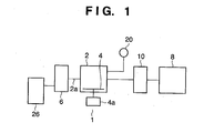
- Fig. 1 is a view schematically showing an apparatus of the first embodiment of the present invention.
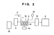
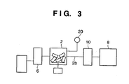
- Figs. 2 to 5 are views for explaining the process of practicing the present invention by using the apparatus shown in Fig. 1.
- reference numeral 1 denotes a pulverizing apparatus; and 2, a pulverizing vessel of the pulverizing apparatus.
- the pulverizing vessel 2 accommodates containers containing a powder to be pulverized, units, parts, and like.
- the pulverizing vessel 2 is made of a metal material and so designed as to have strength with which this pulverizing vessel can stand physical impact when a product to be pulverized is pulverized in the vessel.
- Reference numeral 4 denotes a pulverizing blade which is rotated by a driving means 4a installed outside the pulverizing vessel.
- the pulverizing blade 4 rotates a product to be pulverized placed in the pulverizing vessel and pulverizes the product by the impact force of the blade.
- Reference numeral 6 denotes a dust collector which collects by suction a powder contained in a product to be pulverized.
- the dust collector 6 is connected to a powder suction hole 2a of the pulverizing vessel 2.
- Reference numeral 8 denotes an inert gas generator; and 10, an inert gas supplier.
- nitrogen gas is used as an inert gas.
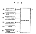
- Fig. 6 is a block diagram showing control blocks for controlling driving of the individual parts of the pulverizing apparatus 1 described above.
- Reference numeral 12 denotes a motor control means for controlling the rotation of a motor as a driving source of the driving means 4a; 14, a motor control means for a suction driving source of the dust collector 6; 16, a driving means of the gas generator 8; 18, a driving means of the gas supplier 10; and 20, a sensor of an oxygen densitometer.
- Reference numeral 22 denotes an overall control means for controlling these control means.
- a product to be pulverized by the pulverization method and apparatus of this embodiment is a container containing a powder.
- main products to be pulverized are toner containers W (toner cartridges) of image forming apparatuses, e.g., copying machines and printers (laser beam printers) manufactured and sold by the present applicant.
- toner containers W are a kind of expendable replaceable units. A printer user discards a toner container after using up the toner, or discards an unused toner container. These toner containers cannot be discarded as general waste products.
- the main constituent members of the body of this toner container W are plastic materials which do not naturally decompose without harming the environment, if they are discarded under ground or water or in natural conditions.
- the container pulverization method according to the present invention is not limited to the aforementioned method of pulverizing a toner-containing cartridge (container) of an image forming apparatus, but solves problems, caused by dust, of containers containing powders in various fields such as office machines, industrial machines, and household electric appliances.
- a cover 3 of the pulverizing vessel 2 is opened, and toner containers W to be pulverized are accommodated in the pulverizing vessel 2.
- the number of the toner containers W to be accommodated is determined on the basis of the volume of the pulverizing vessel 2, the pulverizing ability of the blade 4, and the type of the toner container W to be pulverized.
- the cover 3 of the pulverizing vessel 2 is closed, and nitrogen manufactured by the nitrogen gas generator 8 as an inert gas generator described above is supplied into the pulverizing vessel 2 from the nitrogen gas supplier 10 through a supply port 2b.
- a gas supply amount Q2 is adjusted under the control of the driving means 18 of the gas supplier, in accordance with the volume of the pulverizing vessel 2 and the amount (number) of the charged toner containers W.
- the control means 24 of the dust collector 6 controls an exhaust amount Q3 of the ambient gas in the pulverizing vessel 2, in accordance with conditions such as the number of the toner containers W charged in the pulverizing vessel 2, and the volume of the pulverizing vessel 2.
- the rotational speed of the blade 4 of the pulverizing means is determined by, e.g., the number of the toner containers W to be pulverized, the volume of the vessel, and the construction of the toner container.
- the pulverizing condition settings are changed in accordance with the internal mechanism of the toner container W, and the types of materials used (e.g., the types and ratios of plastic materials, metal materials, rubber materials, paper materials, and some other materials).
- the blade 4 of the pulverizing means is rotated to pulverize the toner containers W in the pulverizing vessel 2.
- toner contained in the toner containers W fills the pulverizing vessel 2 as the toner containers W are destroyed.
- the composition of toner used in a copying machine or laser beam printer contains a binder resin, coloring material, offset preventing material, flowability improving material, cleaning assistant, and the like. Therefore, dust explosion may occur owing to the generation of sparks caused by collision between pulverized metal materials and the pulverizing vessel inner walls when toner containers are pulverized in the pulverizing vessel, and owing to the presence of oxygen in air.
- nitrogen gas is supplied and the ambient gas containing air, toner, and nitrogen gas in -the pulverizing vessel 2 is exhausted in order to hold the oxygen concentration and toner concentration in the pulverizing vessel 2 at predetermined concentrations or lower.
- condition settings of adjustment of the gas supply amount, the exhaust amount of the pulverizing vessel ambient gas, and the oxygen concentration in the pulverizing vessel are changed in accordance with the volume of the vessel 2, the type of toner container, and the like.
- dust explosion was suppressed by controlling the oxygen concentration to 10% or less by densitometer measurement, in accordance with the toner composition, the conditions of the generation of sparks caused by the metal materials forming the toner container, and the like.
- toner cartridges When toner cartridges are pulverized in the pulverizing vessel, toner-containing portions of the toner cartridges are disassembled, and toner particles are scattered. The scattered toner is exhausted as it is mixed with supplied nitrogen gas, and the oxygen concentration in the vessel is decreased to 10% or less. As a consequence, dust explosion is prevented.
- the structures of the pulverized toner containers are disassembled in the pulverizing vessel into pulverized pieces having a predetermined size.
- These pulverized pieces are plastic portions, metal portions, and other constituent material portions of the bodies of the toner containers.
- the size of pieces is determined on the basis of conditions such as the rotational speed of the blade 4 of the pulverizing means, the magnitude of the impact force, which depends upon the volume of the pulverizing vessel, when the pulverized containers are collided against the inner walls of the pulverizing vessel by the rotation of the blade, breaking by collision between the pulverized pieces, and the rotation time of the blade 4.
- the size of pulverized pieces is preferably determined in accordance with the type of processing after the toner containers are pulverized into pieces.
- Dust explosion was prevented by the set oxygen concentration in the pulverizing vessel, even when the residual amount in toner-containing portions of toner containers was large.
- Pulverization is performed under the above condition settings.
- the toner collection amount can be increased by continuously exhausting the ambient gas in the pulverizing vessel and collecting toner in the pulverizing vessel even after the supply of nitrogen gas is stopped after the elapse of the predetermined blade rotation time.
- Fig. 7 shows the main parts of an apparatus according to the second embodiment of the present invention.
- an object to be pulverized is a toner cartridge of a copying machine.
- reference numeral 31 denotes a vessel of a pulverizing apparatus.
- a rotary blade 34 rotated by a driving means 32 is installed, and a volume space 31a for accommodating a plurality of cartridges W to be pulverized is formed.
- This pulverizing vessel 31 is mounted on a base (not shown) to make an inclination angle of 30° ( ⁇ 5° ) with the horizontal surface of the base.
- Reference numeral 31b denotes an upper cover of the vessel.
- the pulverizing vessel 31 is attached to a powder separation chamber 38 via a communication door 31c.
- the separation chamber 38 is also installed at the same inclination angle as the pulverizing vessel.
- Reference numeral 38a denotes the door of the separation chamber.
- a separating means 40 separates a powder staying in a product to be pulverized placed in the separation chamber 38.
- the separating means 40 is a rotary blade.
- the rotary blade 40 is driven by a driving means 40a.
- a powder (toner) collecting means 42 connected to the pulverizing vessel 31 is made up of, e.g., a connecting pipe 42a, dust collecting means 42b, and filter 42c.
- An oxygen concentration measuring means 44 measures information from a concentration sensor installed in the vessel 31.
- An inert gas supply means 46 supplies a gas from a nitrogen gas generating means 46a to the vessel 31 and separation chamber 38 through gas supply means 46b and 46c and supply pipes 46d and 46e, respectively.
- Reference numeral 48 denotes a means for collecting a powder separated from a product to be pulverized.
- the means 48 is made up of, e.g., a connecting pipe 48a, dust collector 48b, and filter 48c.
- Reference numeral 50 denotes an oxygen concentration measuring means of the separation chamber 38.
- the specifications of the apparatus having the arrangement shown in Fig. 7 are as follows.
- Material of vessel 1 SUS (Stainless Steel) Volume of vessel 1 about 0.6 m 3 Inclination angle of vessel 1 30° ( ⁇ 5° )
- Material of pulverizing blade SUS Rotational speed of pulverizing blade 1,300 to 1,600 rpm
- Type of concentration sensor Zirconia type
- Type of inert gas Nitrogen gas Supply amount of nitrogen gas 120 m 3 /hour Collecting capability of dust collector 12 5 m 3 /min
- Material of separation chamber 8 SUS Volume of separation chamber 8 0.2 m 3
- the ambient in the vessel 31 is the atmosphere.
- the oxygen concentration in the pulverizing vessel 31 is checked by measuring a signal from an oxygen concentration measurement sensor by the measuring means 44.
- a control means 54 controls the oxygen concentration in the vessel 31 to 10% or less by adjusting the supply amount of nitrogen gas from the inert gas supply means 46.
- the pulverizing blade 34 starts rotating to pulverize the cartridges W.
- toner in the cartridges is scattered outside the cartridges to fill the pulverizing vessel 31.
- the scattered toner is sequentially collected by the dust collecting means 42.
- the size of pulverized pieces of the cartridges pulverized in the pulverizing vessel 31 is determined on the basis of the pulverizing capability of the rotary blade 34.
- External parts and internal parts of the main components of a container of the cartridge are principally made of plastic materials. However, various materials are used as components, e.g., rubber rollers, metal parts, and gear parts, of the cartridge.
- toner accommodating parts are pulverized to extract internal toner to the outside, and this toner is collected by the dust collecting means 42.
- a plurality of cartridges (17 kg as a supply amount) were charged into the pulverizing vessel 31 under the specification conditions described above, and these cartridges were pulverized at a pulverizing blade rotational speed of 1,400 rpm for 20 sec.
- the pulverizing action in the pulverizing step in the vessel 31 disassembles the cartridge containers and cuts the plastic components into predetermined dimensions.
- the pulverizing vessel Since the pulverizing vessel has an inclination angle, the pulverized products of the pulverized cartridges in the vessel stay in the right corner in Fig. 7. When the communication door 31b of the vessel 31 is opened, these pulverized products slip into the separation chamber 38 by the inclination angle of the vessel.
- the oxygen concentration in the separation chamber 38 is adjusted in the same manner as in the pulverizing vessel 31.
- Toner contained in the cartridges pulverized in the pulverizing vessel 31 is collected by the dust collecting means 42.
- the cartridge containers are not pulverized into small pieces, so a considerable amount of toner still remains in the pulverized plastic pieces.
- the residual toner is also supplied and stick to sorted materials.
- a separation step is performed to increase the efficiency of collection of toner not collected in the pulverizing step.
- the components of the pulverized cartridge containers slipped from the pulverizing vessel 31 into the separation chamber 38 are cut by pulverization. Therefore, the parts of the pulverized products are not flat, and many uneven portions are formed in the corners of these containers. Toner remains in these uneven portions. This residual toner is the toner not collected by the dust collecting means 42 in the pulverizing vessel 31.
- the separation chamber 38 collects this toner.
- Te pulverized products slipped from the pulverizing vessel 31 is impacted by the impacting means 40 in the separation chamber 38.
- the impacting means of this embodiment is a rotary blade formed on the bottom of the separation chamber 38.
- the rotary blade 40 is rotated by the driving means 40a, and the rotation of the blade 40 gives impact to the pulverized products, thereby blowing up the pulverized products staying on the bottom of the separation chamber by the impact. At the same time, toner remaining between these pulverized products is blown up and collected by the dust collecting means 48.
- the rotation of the rotary blade of the separation chamber 48 achieves a function different from that of the rotation for pulverization in the pulverizing vessel 31.
- the rotational speed of this rotary blade is a few revolutions/sec.
- the residual toner is collected by blowing up the toner by the impact to the pulverized products in the separation chamber 38. This greatly reduces the amount of toner contained in the pulverized products remaining in the separation chamber 38.
- the main purpose of pulverization of toner cartridges in the pulverizing step is not to pulverize plastic containers of the toner cartridges into pieces of a few millimeters, but to break and disassemble the container form of the toner cartridges.
Landscapes
- Engineering & Computer Science (AREA)
- Food Science & Technology (AREA)
- Environmental & Geological Engineering (AREA)
- Mechanical Engineering (AREA)
- Crushing And Pulverization Processes (AREA)
- Developing Agents For Electrophotography (AREA)
Abstract
Description
| Product to be pulverized | Toner cartridge |
| Charge amount of product to be pulverized | 10 to 20 kg |
| Volume of pulverizing vessel | 500 liters |
| Number of | 1 |
| Rotational speed of blade | 1,500 rpm |
| Rotation time of | 20 sec |
| Nitrogen gas supply amount Q2 | 6.0 Nm3/min |
| Dust flow rate | 6.0 Nm3/min |
| Upper limit of oxygen concentration in pulverizing | 10% or less |
| Material of | SUS (Stainless Steel) |
| Volume of | about 0.6 m3 |
| Inclination angle of | 30° (±5° ) |
| Material of pulverizing blade | SUS |
| Rotational speed of pulverizing blade | 1,300 to 1,600 rpm |
| Type of concentration sensor | Zirconia type |
| Type of inert gas | Nitrogen gas |
| Supply amount of nitrogen gas | 120 m3/hour |
| Collecting capability of | 5 m3/min |
| Material of | SUS |
| Volume of | 0.2 m3 |
Claims (36)
- A method, comprising:(i) a pulverization step of accommodating a container containing a powder in an accommodating member, and pulverizing the container containing the powder;(ii) a replacement step of replacing the ambient in the accommodating member with an inert gas;(iii) an exhaust step of exhausting the powder and the inert gas in the accommodating member during the pulverization; and(iv) a supply step of supplying an inert gas into the accommodating member during the pulverization.
- The method according to claim 1, wherein the supply amount of inert gas in the supply step is held to be not less than the exhaust amount in the exhaust step.
- The method according to claim 1, wherein in the replacement step, an oxygen concentration in the accommodating member is set at not more than 10%.
- A method of pulverizing a container containing a powder, comprising:a replacement step of accommodating the container containing the powder in an accommodating member, replacing the interior of the accommodating member with an inert gas, and holding the oxygen concentration in the accommodating member at not more than 10%; andan exhaust step of pulverizing the container in the accommodating member, and exhausting the inert gas and the powder in the accommodating member outside the accommodating member during the pulverization.
- The method according to claim 4, further comprising a supply step of supplying the inert gas into the accommodating member to hold the inert gas concentration constant in the accommodating member.
- The method according to claim 5, wherein in the supply step, the oxygen concentration in the accommodating member is held at not more than 10% by supplying the inert gas.
- The method according to claim 4, wherein a supply amount of inert gas in the supply step is held to be not less than an exhaust amount in the exhaust step.
- A method of processing a cartridge containing toner, comprising:a replacement step of accommodating the cartridge containing the toner in an accommodating member, replacing the interior of the accommodating member with an inert gas, and holding the oxygen concentration in the accommodating member at not more than 10%; andan exhaust step of pulverizing the cartridge in the accommodating member, and exhausting the inert gas and the toner in the accommodating member outside the accommodating member during the pulverization.
- The method according to claim 8, wherein the inert gas is supplied into the accommodating member to hold the inert gas concentration constant in the accommodating member.
- The method according to claim 8, wherein in the replacement step, the oxygen concentration in the accommodating member is held at not more than 10% by supplying the inert gas.
- The method according to claim 8, wherein a supply amount of inert gas in the replacement step is held to be not less than an exhaust amount in the exhaust step.
- An apparatus for pulverizing a container containing a powder, comprising:an accommodating member for accommodating the container containing the powder;pulverizing means for pulverizing the container;means for replacing the ambient in said accommodating member with an inert gas; andmeans for exhausting the inert gas and the powder in said accommodating member.
- The apparatus according to claim 12, further comprising means for supplying the inert gas into said accommodating member.
- The apparatus according to claim 13, further comprising means for controlling an oxygen concentration in said accommodating member.
- The apparatus according to claim 14, wherein said control means further comprises means for measuring the oxygen concentration in said accommodating member.
- A method of processing a toner-containing cartridge of an image forming apparatus, comprising:a replacement step of accommodating the toner-containing cartridge of the image forming apparatus in an accommodating member, and replacing the ambient in the accommodating member with an inert gas; anda separation step of pulverizing the toner in the accommodating member, collecting the toner and the inert gas in the accommodating member by exhausting the toner and the inert gas outside the accommodating member, and separating the toner.
- A method of pulverizing a container containing a powder, wherein after the container containing the powder is pulverized, the powder is separated from the pulverized product.
- A method of pulverizing a container containing a powder, wherein after the container containing the powder is pulverized into a predetermined size or pulverized with a predetermined pulverizing force, the pulverized powder is collected while impact is given to the pulverized product containing the pulverized powder.
- The method according to claim 18, wherein the impact to the pulverized product is vibration.
- A method of pulverizing a container containing a powder, wherein after the powder contained in the container is collected while the container is pulverized, the powder is collected while the pulverized product is given vibrations.
- The method according to claim 20, wherein the container is pulverized in an inert gas ambient.
- The method according to claim 20, wherein the pulverized product is given vibrations in an inert gas ambient.
- A method of pulverizing a cartridge of an image forming apparatus, wherein after the cartridge of the image forming apparatus is pulverized, toner is separated from the pulverized product.
- A method of pulverizing a cartridge of an image forming apparatus, wherein after the cartridge of the image forming apparatus is pulverized into a predetermined size or pulverized with a predetermined pulverizing force, the pulverized toner is collected while impact is given to the pulverized product containing the pulverized toner.
- A method of pulverizing a cartridge of an image forming apparatus, wherein after toner is collected while the cartridge of the image forming apparatus is pulverized, the toner is collected while the pulverized product is given vibrations.
- The method according to claim 25, wherein the cartridge is pulverized in an inert gas ambient.
- The method according to claim 26, wherein the pulverized product is given vibrations in an inert gas ambient.
- An apparatus for pulverizing a container containing a powder, comprising:pulverizing means for pulverizing the container containing the powder with a predetermined pulverizing force; andvibrating means for giving vibrations to the pulverized product.
- The apparatus according to claim 28, wherein said vibrating means further comprises means for giving vibrations to the pulverized product in an inert gas ambient.
- An apparatus for pulverizing a container containing a powder, comprising:a pulverizing unit including pulverizing means for pulverizing a container containing a powder; andan impacting unit including impacting means for giving impact to the pulverized product pulverized by said pulverizing unit.
- The apparatus according to claim 30, wherein said impacting means comprises vibrating means for giving vibrations to the pulverized product.
- The apparatus according to claim 31, further comprising means for setting an inert gas ambient in said pulverizing unit and said impacting unit.
- A powder collecting method wherein a container containing a powder is pulverized, the powder is separated by giving impact to the pulverized product, and the separated powder is collected by suction.
- The method according to claim 33, wherein the pulverized product is given impact in an inert gas ambient.
- A method of collecting toner contained in a cartridge, wherein the cartridge containing the toner is pulverized, the toner is separated by giving impact to the pulverized product, and the separated toner is collected by suction.
- An apparatus for pulverizing a container containing a powder, comprising:a pulverizing chamber for accommodating and pulverizing the container containing the powder; andan impact giving chamber which communicates with said pulverizing chamber, receives the pulverized product pulverized in said pulverizing chamber, and gives impact to the pulverized product.
Applications Claiming Priority (4)
| Application Number | Priority Date | Filing Date | Title |
|---|---|---|---|
| JP2002108224A JP2003299980A (en) | 2002-04-10 | 2002-04-10 | Method of crushing container containing powder, method of treating cartridge, and method of treating toner for image formation |
| JP2002108224 | 2002-04-10 | ||
| JP2002229906 | 2002-08-07 | ||
| JP2002229906A JP3799309B2 (en) | 2002-08-07 | 2002-08-07 | Method and apparatus for crushing containers containing powder |
Publications (3)
| Publication Number | Publication Date |
|---|---|
| EP1352693A2 true EP1352693A2 (en) | 2003-10-15 |
| EP1352693A3 EP1352693A3 (en) | 2004-06-09 |
| EP1352693B1 EP1352693B1 (en) | 2006-12-06 |
Family
ID=28456383
Family Applications (1)
| Application Number | Title | Priority Date | Filing Date |
|---|---|---|---|
| EP20030007888 Expired - Lifetime EP1352693B1 (en) | 2002-04-10 | 2003-04-07 | Method and apparatus for pulverizing container containing powder |
Country Status (4)
| Country | Link |
|---|---|
| US (1) | US20030192969A1 (en) |
| EP (1) | EP1352693B1 (en) |
| CN (1) | CN100393419C (en) |
| DE (1) | DE60310152T2 (en) |
Cited By (1)
| Publication number | Priority date | Publication date | Assignee | Title |
|---|---|---|---|---|
| CN114377803A (en) * | 2022-01-12 | 2022-04-22 | 杨振宙 | Crushing equipment of broken wall of traditional chinese medicine |
Families Citing this family (11)
| Publication number | Priority date | Publication date | Assignee | Title |
|---|---|---|---|---|
| JP4343519B2 (en) * | 2002-11-26 | 2009-10-14 | キヤノン株式会社 | Process cartridge plastic material recycling method |
| JP4429008B2 (en) * | 2003-12-22 | 2010-03-10 | サントリーホールディングス株式会社 | Gas replacement device and gas replacement method |
| HK1177381A2 (en) * | 2012-12-21 | 2013-08-23 | Ltg Green-Tech R&D Company Limited | A system and method for processing objects having contaminating particles |
| CN104275050B (en) * | 2014-10-24 | 2015-12-02 | 浙江百事德办公设备有限公司 | A kind of dedusting apparatus for work for splitting toner cartridge |
| CN104941987A (en) * | 2015-06-30 | 2015-09-30 | 无锡市绿之星环保有限公司 | Kitchen waste treatment equipment and working method thereof |
| CN105537189B (en) * | 2015-12-10 | 2018-01-02 | 重庆润际远东新材料科技有限公司 | A kind of sewage disposal for silica flour production and safe crushing system |
| CN105344656A (en) * | 2015-12-10 | 2016-02-24 | 重庆润际远东新材料科技有限公司 | First-washing and last-crushing type silicon powder crushing processing equipment |
| CN105537188B (en) * | 2015-12-10 | 2017-12-29 | 重庆润际远东新材料科技有限公司 | A kind of silica flour production line water circulation recycles and safe breaker |
| CN105344655A (en) * | 2015-12-10 | 2016-02-24 | 重庆润际远东新材料科技有限公司 | Cleaning-before-crushing type silicon powder safety and explosion prevention production line |
| DE102018103702A1 (en) * | 2018-02-20 | 2019-08-22 | Brandenburgische Technische Universität Cottbus-Senftenberg | crushing system |
| IT201900003651A1 (en) * | 2019-03-13 | 2020-09-13 | A R G Di Yanez Jose Luis | Shredder machine, particularly for the recycling of materials deriving from printing components and the like. |
Family Cites Families (12)
| Publication number | Priority date | Publication date | Assignee | Title |
|---|---|---|---|---|
| NZ198307A (en) * | 1981-09-08 | 1986-04-11 | Barmac Ass Ltd | Vertical impact pulveriser:secondary mineral feed stream surrounds thrown primary feed |
| CN1116974A (en) * | 1994-08-17 | 1996-02-21 | 戴自梁 | Producing method for -325 mesh zinc powder |
| DE19520365A1 (en) * | 1995-06-08 | 1996-12-12 | Wilhelm Elges | Recycling used toner cartridges from printers and copiers |
| CN1058254C (en) * | 1997-11-03 | 2000-11-08 | 李道火 | Preparation of nanometer-level active composite powder |
| FR2782023B1 (en) * | 1998-08-05 | 2000-09-08 | Air Liquide | DEVICE AND METHOD FOR GRINDING CLOSED CONTAINERS CONTAINING POWDER |
| US6360678B1 (en) * | 1998-08-21 | 2002-03-26 | Fuji Car Mfg. Co., Ltd. | Method and device for disposing of scrapped gas container |
| JP4221486B2 (en) * | 1999-03-29 | 2009-02-12 | 株式会社仲田コーティング | Blasting method and blasting apparatus |
| JP3591412B2 (en) * | 1999-05-31 | 2004-11-17 | 松下電器産業株式会社 | Crushing equipment |
| JP3612454B2 (en) * | 1999-10-01 | 2005-01-19 | 松下電器産業株式会社 | Rotary crusher provided with exhaust circulation means, control method thereof, and waste treatment apparatus using the crusher |
| US6227472B1 (en) * | 1999-11-20 | 2001-05-08 | Robert Ryan | Stonecrusher with externally adjustable anvil ring |
| JP3666791B2 (en) * | 2000-01-27 | 2005-06-29 | キヤノン化成株式会社 | Toner separation processing method and processing system for used toner cartridge |
| CN2493270Y (en) * | 2001-07-25 | 2002-05-29 | 杨志勇 | Multi-function crystallizer |
-
2003
- 2003-04-04 US US10/406,506 patent/US20030192969A1/en not_active Abandoned
- 2003-04-07 DE DE2003610152 patent/DE60310152T2/en not_active Expired - Lifetime
- 2003-04-07 EP EP20030007888 patent/EP1352693B1/en not_active Expired - Lifetime
- 2003-04-08 CN CNB031095194A patent/CN100393419C/en not_active Expired - Fee Related
Cited By (2)
| Publication number | Priority date | Publication date | Assignee | Title |
|---|---|---|---|---|
| CN114377803A (en) * | 2022-01-12 | 2022-04-22 | 杨振宙 | Crushing equipment of broken wall of traditional chinese medicine |
| CN114377803B (en) * | 2022-01-12 | 2023-08-04 | 江西奉原生态科技有限公司 | Broken equipment of traditional chinese medicine broken wall |
Also Published As
| Publication number | Publication date |
|---|---|
| DE60310152D1 (en) | 2007-01-18 |
| US20030192969A1 (en) | 2003-10-16 |
| EP1352693A3 (en) | 2004-06-09 |
| EP1352693B1 (en) | 2006-12-06 |
| CN100393419C (en) | 2008-06-11 |
| CN1449868A (en) | 2003-10-22 |
| DE60310152T2 (en) | 2007-09-27 |
Similar Documents
| Publication | Publication Date | Title |
|---|---|---|
| EP1352693B1 (en) | Method and apparatus for pulverizing container containing powder | |
| JP3642733B2 (en) | Equipment for separating and collecting laminated glass into glass pieces and interlayer pieces | |
| JP3541127B2 (en) | How to treat shredder dust | |
| JP4035980B2 (en) | Resin material separation method for tile carpet | |
| CN100360241C (en) | Method and apparatus for extracting toner from a toner cartridge | |
| CN112121909A (en) | Construction waste crushing and grading treatment device | |
| KR102532189B1 (en) | secondary battery material recycling system | |
| JP4343519B2 (en) | Process cartridge plastic material recycling method | |
| CN100400168C (en) | Method for processing worn-out fluorescent tube | |
| CN103878164B (en) | System and method for treating objects with contaminant particles | |
| JP5127762B2 (en) | Waste treatment facility | |
| JP2001009434A (en) | Waste gypsum board processing method and apparatus | |
| JP3086796B2 (en) | Fine grinding equipment | |
| JP4366072B2 (en) | Method for recycling metal material of process cartridge containing toner | |
| JP3799309B2 (en) | Method and apparatus for crushing containers containing powder | |
| JP2006088087A (en) | Sand making equipment | |
| JP5127761B2 (en) | Waste treatment facility | |
| JP2003299980A (en) | Method of crushing container containing powder, method of treating cartridge, and method of treating toner for image formation | |
| JP2007330904A (en) | Wind sorting device and waste plastic sorting system | |
| JP3126091B2 (en) | Board crushing equipment | |
| JP2000084424A (en) | Apparatus for pulverizing waste gypsum board | |
| JP2004041995A (en) | Glass material recovery method and recovery device | |
| JP3729034B2 (en) | Waste separation and recovery method and apparatus | |
| JPH09150137A (en) | Disposal method of image forming apparatus | |
| JPH1199340A (en) | Crusher |
Legal Events
| Date | Code | Title | Description |
|---|---|---|---|
| PUAI | Public reference made under article 153(3) epc to a published international application that has entered the european phase |
Free format text: ORIGINAL CODE: 0009012 |
|
| AK | Designated contracting states |
Kind code of ref document: A2 Designated state(s): AT BE BG CH CY CZ DE DK EE ES FI FR GB GR HU IE IT LI LU MC NL PT RO SE SI SK TR |
|
| AX | Request for extension of the european patent |
Extension state: AL LT LV MK |
|
| PUAL | Search report despatched |
Free format text: ORIGINAL CODE: 0009013 |
|
| AK | Designated contracting states |
Kind code of ref document: A3 Designated state(s): AT BE BG CH CY CZ DE DK EE ES FI FR GB GR HU IE IT LI LU MC NL PT RO SE SI SK TR |
|
| AX | Request for extension of the european patent |
Extension state: AL LT LV MK |
|
| RIC1 | Information provided on ipc code assigned before grant |
Ipc: 7B 09B 5/00 A Ipc: 7B 02C 18/12 B Ipc: 7B 02C 23/24 B |
|
| 17P | Request for examination filed |
Effective date: 20041209 |
|
| AKX | Designation fees paid |
Designated state(s): DE FR GB |
|
| 17Q | First examination report despatched |
Effective date: 20050126 |
|
| GRAP | Despatch of communication of intention to grant a patent |
Free format text: ORIGINAL CODE: EPIDOSNIGR1 |
|
| GRAS | Grant fee paid |
Free format text: ORIGINAL CODE: EPIDOSNIGR3 |
|
| GRAA | (expected) grant |
Free format text: ORIGINAL CODE: 0009210 |
|
| AK | Designated contracting states |
Kind code of ref document: B1 Designated state(s): DE FR GB |
|
| REG | Reference to a national code |
Ref country code: GB Ref legal event code: FG4D |
|
| REF | Corresponds to: |
Ref document number: 60310152 Country of ref document: DE Date of ref document: 20070118 Kind code of ref document: P |
|
| ET | Fr: translation filed | ||
| PLBE | No opposition filed within time limit |
Free format text: ORIGINAL CODE: 0009261 |
|
| STAA | Information on the status of an ep patent application or granted ep patent |
Free format text: STATUS: NO OPPOSITION FILED WITHIN TIME LIMIT |
|
| 26N | No opposition filed |
Effective date: 20070907 |
|
| REG | Reference to a national code |
Ref country code: FR Ref legal event code: PLFP Year of fee payment: 14 |
|
| PGFP | Annual fee paid to national office [announced via postgrant information from national office to epo] |
Ref country code: DE Payment date: 20160430 Year of fee payment: 14 Ref country code: GB Payment date: 20160427 Year of fee payment: 14 |
|
| PGFP | Annual fee paid to national office [announced via postgrant information from national office to epo] |
Ref country code: FR Payment date: 20160426 Year of fee payment: 14 |
|
| REG | Reference to a national code |
Ref country code: DE Ref legal event code: R119 Ref document number: 60310152 Country of ref document: DE |
|
| GBPC | Gb: european patent ceased through non-payment of renewal fee |
Effective date: 20170407 |
|
| REG | Reference to a national code |
Ref country code: FR Ref legal event code: ST Effective date: 20171229 |
|
| PG25 | Lapsed in a contracting state [announced via postgrant information from national office to epo] |
Ref country code: DE Free format text: LAPSE BECAUSE OF NON-PAYMENT OF DUE FEES Effective date: 20171103 Ref country code: FR Free format text: LAPSE BECAUSE OF NON-PAYMENT OF DUE FEES Effective date: 20170502 |
|
| PG25 | Lapsed in a contracting state [announced via postgrant information from national office to epo] |
Ref country code: GB Free format text: LAPSE BECAUSE OF NON-PAYMENT OF DUE FEES Effective date: 20170407 |