EP1350999A1 - Vanne électromagnétique - Google Patents
Vanne électromagnétique Download PDFInfo
- Publication number
- EP1350999A1 EP1350999A1 EP20020007103 EP02007103A EP1350999A1 EP 1350999 A1 EP1350999 A1 EP 1350999A1 EP 20020007103 EP20020007103 EP 20020007103 EP 02007103 A EP02007103 A EP 02007103A EP 1350999 A1 EP1350999 A1 EP 1350999A1
- Authority
- EP
- European Patent Office
- Prior art keywords
- solenoid valve
- fixed core
- valve according
- passage
- pneumatic
- Prior art date
- Legal status (The legal status is an assumption and is not a legal conclusion. Google has not performed a legal analysis and makes no representation as to the accuracy of the status listed.)
- Granted
Links
- 230000005291 magnetic effect Effects 0.000 claims abstract description 10
- 239000003302 ferromagnetic material Substances 0.000 claims abstract description 4
- 238000004026 adhesive bonding Methods 0.000 claims description 3
- 238000007789 sealing Methods 0.000 claims 1
- 238000002347 injection Methods 0.000 abstract description 4
- 239000007924 injection Substances 0.000 abstract description 4
- 239000012530 fluid Substances 0.000 description 5
- 239000002184 metal Substances 0.000 description 5
- 229910052751 metal Inorganic materials 0.000 description 5
- 238000004519 manufacturing process Methods 0.000 description 4
- 238000000926 separation method Methods 0.000 description 4
- 230000007423 decrease Effects 0.000 description 3
- 230000005294 ferromagnetic effect Effects 0.000 description 3
- 239000012528 membrane Substances 0.000 description 3
- 238000000034 method Methods 0.000 description 3
- 230000000694 effects Effects 0.000 description 2
- 238000005516 engineering process Methods 0.000 description 2
- 230000009471 action Effects 0.000 description 1
- 239000011230 binding agent Substances 0.000 description 1
- 238000010276 construction Methods 0.000 description 1
- 230000001419 dependent effect Effects 0.000 description 1
- 238000010586 diagram Methods 0.000 description 1
- 239000000806 elastomer Substances 0.000 description 1
- 229920001971 elastomer Polymers 0.000 description 1
- 238000009434 installation Methods 0.000 description 1
- 230000010354 integration Effects 0.000 description 1
- 238000003754 machining Methods 0.000 description 1
- 239000000463 material Substances 0.000 description 1
- 230000007246 mechanism Effects 0.000 description 1
- 150000002739 metals Chemical class 0.000 description 1
- 239000000203 mixture Substances 0.000 description 1
- 238000012986 modification Methods 0.000 description 1
- 230000004048 modification Effects 0.000 description 1
- 239000000843 powder Substances 0.000 description 1
- 239000011347 resin Substances 0.000 description 1
- 229920005989 resin Polymers 0.000 description 1
- 230000000717 retained effect Effects 0.000 description 1
- 238000010079 rubber tapping Methods 0.000 description 1
- 238000005245 sintering Methods 0.000 description 1
Images



Classifications
-
- F—MECHANICAL ENGINEERING; LIGHTING; HEATING; WEAPONS; BLASTING
- F16—ENGINEERING ELEMENTS AND UNITS; GENERAL MEASURES FOR PRODUCING AND MAINTAINING EFFECTIVE FUNCTIONING OF MACHINES OR INSTALLATIONS; THERMAL INSULATION IN GENERAL
- F16K—VALVES; TAPS; COCKS; ACTUATING-FLOATS; DEVICES FOR VENTING OR AERATING
- F16K31/00—Actuating devices; Operating means; Releasing devices
- F16K31/02—Actuating devices; Operating means; Releasing devices electric; magnetic
- F16K31/06—Actuating devices; Operating means; Releasing devices electric; magnetic using a magnet, e.g. diaphragm valves, cutting off by means of a liquid
- F16K31/0603—Multiple-way valves
- F16K31/0624—Lift valves
-
- F—MECHANICAL ENGINEERING; LIGHTING; HEATING; WEAPONS; BLASTING
- F15—FLUID-PRESSURE ACTUATORS; HYDRAULICS OR PNEUMATICS IN GENERAL
- F15B—SYSTEMS ACTING BY MEANS OF FLUIDS IN GENERAL; FLUID-PRESSURE ACTUATORS, e.g. SERVOMOTORS; DETAILS OF FLUID-PRESSURE SYSTEMS, NOT OTHERWISE PROVIDED FOR
- F15B13/00—Details of servomotor systems ; Valves for servomotor systems
- F15B13/02—Fluid distribution or supply devices characterised by their adaptation to the control of servomotors
- F15B13/04—Fluid distribution or supply devices characterised by their adaptation to the control of servomotors for use with a single servomotor
- F15B13/0401—Valve members; Fluid interconnections therefor
- F15B13/0405—Valve members; Fluid interconnections therefor for seat valves, i.e. poppet valves
-
- F—MECHANICAL ENGINEERING; LIGHTING; HEATING; WEAPONS; BLASTING
- F15—FLUID-PRESSURE ACTUATORS; HYDRAULICS OR PNEUMATICS IN GENERAL
- F15B—SYSTEMS ACTING BY MEANS OF FLUIDS IN GENERAL; FLUID-PRESSURE ACTUATORS, e.g. SERVOMOTORS; DETAILS OF FLUID-PRESSURE SYSTEMS, NOT OTHERWISE PROVIDED FOR
- F15B13/00—Details of servomotor systems ; Valves for servomotor systems
- F15B13/02—Fluid distribution or supply devices characterised by their adaptation to the control of servomotors
- F15B13/04—Fluid distribution or supply devices characterised by their adaptation to the control of servomotors for use with a single servomotor
- F15B13/044—Fluid distribution or supply devices characterised by their adaptation to the control of servomotors for use with a single servomotor operated by electrically-controlled means, e.g. solenoids, torque-motors
-
- F—MECHANICAL ENGINEERING; LIGHTING; HEATING; WEAPONS; BLASTING
- F16—ENGINEERING ELEMENTS AND UNITS; GENERAL MEASURES FOR PRODUCING AND MAINTAINING EFFECTIVE FUNCTIONING OF MACHINES OR INSTALLATIONS; THERMAL INSULATION IN GENERAL
- F16K—VALVES; TAPS; COCKS; ACTUATING-FLOATS; DEVICES FOR VENTING OR AERATING
- F16K27/00—Construction of housing; Use of materials therefor
- F16K27/003—Housing formed from a plurality of the same valve elements
-
- F—MECHANICAL ENGINEERING; LIGHTING; HEATING; WEAPONS; BLASTING
- F16—ENGINEERING ELEMENTS AND UNITS; GENERAL MEASURES FOR PRODUCING AND MAINTAINING EFFECTIVE FUNCTIONING OF MACHINES OR INSTALLATIONS; THERMAL INSULATION IN GENERAL
- F16K—VALVES; TAPS; COCKS; ACTUATING-FLOATS; DEVICES FOR VENTING OR AERATING
- F16K31/00—Actuating devices; Operating means; Releasing devices
- F16K31/02—Actuating devices; Operating means; Releasing devices electric; magnetic
- F16K31/06—Actuating devices; Operating means; Releasing devices electric; magnetic using a magnet, e.g. diaphragm valves, cutting off by means of a liquid
- F16K31/0603—Multiple-way valves
- F16K31/0606—Multiple-way valves fluid passing through the solenoid coil
-
- F—MECHANICAL ENGINEERING; LIGHTING; HEATING; WEAPONS; BLASTING
- F16—ENGINEERING ELEMENTS AND UNITS; GENERAL MEASURES FOR PRODUCING AND MAINTAINING EFFECTIVE FUNCTIONING OF MACHINES OR INSTALLATIONS; THERMAL INSULATION IN GENERAL
- F16K—VALVES; TAPS; COCKS; ACTUATING-FLOATS; DEVICES FOR VENTING OR AERATING
- F16K31/00—Actuating devices; Operating means; Releasing devices
- F16K31/02—Actuating devices; Operating means; Releasing devices electric; magnetic
- F16K31/06—Actuating devices; Operating means; Releasing devices electric; magnetic using a magnet, e.g. diaphragm valves, cutting off by means of a liquid
- F16K31/0603—Multiple-way valves
- F16K31/0624—Lift valves
- F16K31/0627—Lift valves with movable valve member positioned between seats
-
- H—ELECTRICITY
- H01—ELECTRIC ELEMENTS
- H01F—MAGNETS; INDUCTANCES; TRANSFORMERS; SELECTION OF MATERIALS FOR THEIR MAGNETIC PROPERTIES
- H01F7/00—Magnets
- H01F7/06—Electromagnets; Actuators including electromagnets
- H01F7/08—Electromagnets; Actuators including electromagnets with armatures
- H01F7/081—Magnetic constructions
-
- H—ELECTRICITY
- H01—ELECTRIC ELEMENTS
- H01F—MAGNETS; INDUCTANCES; TRANSFORMERS; SELECTION OF MATERIALS FOR THEIR MAGNETIC PROPERTIES
- H01F7/00—Magnets
- H01F7/06—Electromagnets; Actuators including electromagnets
- H01F7/08—Electromagnets; Actuators including electromagnets with armatures
- H01F7/16—Rectilinearly-movable armatures
- H01F7/1638—Armatures not entering the winding
-
- Y—GENERAL TAGGING OF NEW TECHNOLOGICAL DEVELOPMENTS; GENERAL TAGGING OF CROSS-SECTIONAL TECHNOLOGIES SPANNING OVER SEVERAL SECTIONS OF THE IPC; TECHNICAL SUBJECTS COVERED BY FORMER USPC CROSS-REFERENCE ART COLLECTIONS [XRACs] AND DIGESTS
- Y10—TECHNICAL SUBJECTS COVERED BY FORMER USPC
- Y10T—TECHNICAL SUBJECTS COVERED BY FORMER US CLASSIFICATION
- Y10T137/00—Fluid handling
- Y10T137/8593—Systems
- Y10T137/86493—Multi-way valve unit
- Y10T137/86574—Supply and exhaust
- Y10T137/86622—Motor-operated
-
- Y—GENERAL TAGGING OF NEW TECHNOLOGICAL DEVELOPMENTS; GENERAL TAGGING OF CROSS-SECTIONAL TECHNOLOGIES SPANNING OVER SEVERAL SECTIONS OF THE IPC; TECHNICAL SUBJECTS COVERED BY FORMER USPC CROSS-REFERENCE ART COLLECTIONS [XRACs] AND DIGESTS
- Y10—TECHNICAL SUBJECTS COVERED BY FORMER USPC
- Y10T—TECHNICAL SUBJECTS COVERED BY FORMER US CLASSIFICATION
- Y10T137/00—Fluid handling
- Y10T137/8593—Systems
- Y10T137/87169—Supply and exhaust
- Y10T137/87217—Motor
Definitions
- the present invention relates to electromagnetic valves.
- the principle of these solenoid valves is to be able to control by a mechanism electromagnetic the application of pressure on a specific location and / or the passage of a fluid or gas by opening or closing an orifice that controls the outlet of the fluid or gas.
- solenoid valves we are interested in miniaturize them.
- the main parts of a solenoid valve are normally a electromagnet, which is usually composed of a fixed core and a coil, a mobile core and a supporting structure. Necessity by the way of assembly, the desired uses or other reasons, they are added to these three main parts usually many parts to specific destination.
- a solenoid valve also requires electrical connections and tires. This leads to disadvantages at the design level complex, functionality and editing, especially in the case of connections conventionally carried out by connecting the inputs and / or outputs of pressure of the solenoid valves by a pneumatic base, thus requiring a complicated design of the latter.
- the object of the present invention is to overcome the aforementioned drawbacks and to allow the realization of a solenoid valve composed of a minimal number of parts using ferromagnetic metal injection technology for the manufacture of multifunctional complex parts, preferably of shape rectangular to optimize the contact area between the fixed core and the core moving of the solenoid valve, the central part thus incorporating at least a part pneumatic and / or electrical connections.
- the object of the present invention is an electromagnetic valve which distinguishes for this purpose by the features set forth in claim 1 and / or the dependent claims.
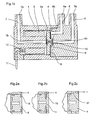
- Figures 1a, 1b and 1c schematically illustrate the principle of a solenoid valve with an electromagnet with a flat plunger or with a solenoid piston plunger, a common orifice being integrated in a fixed core or in a body.
- Figures 2a, 2b and 2c show examples of the assembly of a solenoid valve by gluing, stapling or clipping.
- Figure 3 shows an example of pneumatic and electrical connection standardized and centralized for the simplification of inter-
- Figures 4a to 4f schematically show different types of fixation a solenoid valve on a pneumatic base.
- Figures 5a-c schematically show several other forms of executions of a three-way solenoid valve.
- Figures 6a-d show schematically different shapes of execution of a two-way solenoid valve.
- the solenoid valve shown in FIG. 1a is an electromagnetic valve three-way and two positions that can operate in three-way mode normally open, in normally closed three-way mode, or in Selector or distributor, simply changing the positions of the connection inlet and outlet pressure.
- the solenoid valve comprises three main parts, a fixed core 1 in one single piece housing a coil 2 in a corresponding housing, a core mobile 3, and a body 4.
- the fixed core 1 and the body 4 compose the structure the solenoid valve, the fixed core 1 and the coil 2 form together the electromagnet.
- the mobile core 3 can be realized as a diver plate 3a, as shown in FIGS. 1a and 1c, or as piston plunger 3b, as in Figure 1b.
- the plunger is placed concentrically with respect to the axis of the solenoid valve in a chamber 9 between the fixed core 1 and the body 4, in front of the coil 2.
- the pressure inlet passage 5 and the exhaust passage 7 are located partially in the axis of the valve, the central portion of the plunger 3 is then intended to serve as a valve and to close alternately the inner inlet opening 5b or the inner exhaust port 7b which have the shape of a nozzle.
- An elastomer 10 is overmolded for this purpose, either in one or two rooms in the center of the diver.
- a return spring 8 is installed in the chamber 9 between the fixed core 1 and 4.
- This spring can be helical or flat and keeps the diver in a first position in which the inner inlet port 5b is closed and the orifice 7b exhaust interior is open.
- the diver takes, against the action of this spring, his second position in which the inner inlet port 5b is open and the inner exhaust port 7b is closed, thus making it possible to apply a pressure on the common external orifice 6a.
- the return spring brings the plunger 3 back into its first position allowing gas or fluid to escape through the passage exhaust 7 and thus to remove the pressure on the common outer orifice 6a.
- connection of the pressure inlet to the orifice common outside 6a allows the use of the solenoid valve in "selector" mode; the connecting two pressure ports to the outside inlet port 5a and the external exhaust port 7a is called the “distributor" mode.
- the plunger 3, the return spring 8 and their housing, as well as the solenoid valve as a whole, may be rectangular or oval. This geometry increases the contact area between the plunger 3 and the core fixed 1 of the electromagnet and thus the magnetic force, thus making it possible to reduce the width of the solenoid valve.
- a flat spring 8 must not be retained only by its two ends, thus presenting a force of lower booster as well as lower stresses inside the spring only in a circular construction.
- the fixed core 1 is manufactured by a metal injection technology in one piece and a ferromagnetic material. This technique consists of inject a mixture of metal powder and plastic binder, then to deal with and sinter the resulting piece. The piece is injected on an oversized scale so that at sintering it recovers its normal dimensions.
- the fixed core manufactured in such a way in one piece then allows to accumulate several functions.
- this unique piece performs the function of fixed core and magnetic circuit of the electromagnet, the material and the manufacturing process ensuring its magnetic characteristics. It has a ring groove hosting the coil 2.
- this room is designed to accommodate the passages of the Pneumatic and electrical connection of the solenoid valve. It can therefore, as shown in Figure 1a or 1b, include an exhaust passage 7 of pressure with the outer exhaust port 7a and the inner port exhaust 7b and a common passage 6 with the common external orifice 6a and the common inner hole 6b. Or it can, as in Figure 1c, have only the exhaust passage 7 with the corresponding orifices.
- the body 4 normally made of plastic in these cases is only one pressure inlet passage 5 with the external inlet port 5a and the orifice inside 5b, the inlet passage 5 and the common passage 6 with the corresponding holes.
- the inlet opening 5b has a nozzle opposite of the center of a movable core 3
- the internal exhaust port 7b has a nozzle in front of the center on the other side of the movable core 3.
- this single piece contains only passages inside without the protruding parts shown in Figures 1a-c, or that the protruding parts of the passages are made by pieces to be integrated by corresponding holes and provided for this purpose. effect in the fixed core.
- Outer ports may be in line or on any face of the valve; it is possible in particular that the external orifice 7a is located perpendicularly or parallel to the axis of the valve, that the three outer ports 5a, 6a, 7a are located in the same plane, or that the outer exhaust port 7a and the outer inlet port 5a lie in the same plane, the common external orifice 6a being perpendicular at this level.
- This can be accompanied by a corresponding arrangement of the passage for the electrical connection, such as the integration of a connection centralized electric 14 in the same plane, described in detail later in this document.
- this single piece of the fixed core 1 is arranged so as to allow the final assembly of the solenoid valve between the fixed core 1 and the body 4.
- the piece has a geometric shape allowing either gluing, by example using a resin seal 15 placed in a groove of the body 4 and chemically adhering with the metal of the fixed core 1, ie the passage of pins or staples 16, or the attachment by clips 17, which is illustrated in FIGS. 2a-2c.
- this single piece may have lugs 13, supports or holes adapted to ensure the intervanne fixing or fixing the solenoid valve on a pneumatic base 20.
- the inlet and outlet ports of pressure can be arranged differently. It is therefore possible, and illustrated at FIG. 3, to make a pneumatic and electrical connection making it possible to connect directly between the solenoid valves the inputs and / or pressure outlets. This is possible if the inlet passage 5 and the exhaust passage 7 pressure each have two standardized outer outlets on two opposite sides of the solenoid valve, and positioning these external inlet ports 5a and these external exhaust ports 7a and, optionally, the connection centralized electric 14 in a plane, and the common external orifice perpendicular to it. The assembly of several valves then generates the complete pneumatic and electrical connection of the assembly.
- This arrangement allows in particular the simplification of the electrical connection of a group interconnected solenoid valves in the sense that the connectors 14 are standardized, integrated into the body 4 by crossing it parallel to the orifices interconnecting tires, and ordered from a solenoid valve which houses the external electrical connections.
- FIGS. 4a to 4f the fixing on a base is possible, among other things, by different types of fixation illustrated, namely the fixing using screws 21 (FIGS. 4a and 4b), clips 22 (FIG. 4c), rails 23 (FIG. 4d), a system bayonet 24, which is obviously interesting for shape valves cylindrical as shown in Figure 4e, or using the tips pneumatic tires ( Figure 4f).
- the fact of arranging for the arrangement of the fixed core of complex geometric shapes and adapted to ensure the fixation intervanne or on a base while having only one piece for the fixed core is therefore particularly advantageous.
- the electrical connection of the solenoid shown in this document covers several systems.
- two pins 11 planted above the core 12 of the coil 2, on which the wires of the coil are fixed and which pass through the fixed core 1 through a plugged hole so sealed after installation, are used directly as connectors External.
- These pins 11 may be straight or curved after the introduction of the coil 2 in its housing.
- the pins can also be used as plugs males of a connector or can be soldered to an electronic plate exterior.
- Figure 5a shows an execution of a solenoid valve which comprises still a ring-shaped permanent magnet 18 placed concentrically at the axis of the valve in the central part of the fixed core 1.
- this permanent magnet 18 serves to increase the force magnetic generated by the fixed core after being magnetized.
- Figure 5b shows an electromagnetic valve with a different pneumatic laying plan.
- the single piece of the fixed core 1 serves as a magnetic circuit, housing the coil 2, passages for the electrical connection, and fastening for the valve assembly and for the intervanne connection as mentioned above but the passages pneumatic tires are exclusively integrated into the body.
- the external openings (5a, 6a, 7a) of all the pneumatic passages example parallel to the axis of the valve on the open side and oriented to outside the body 4.
- the fixed core 1 is in this case equipped with two coils 2 housed in two ring gorges.
- Two corresponding 3 mobile cores are placed in a manner similar to that described above in two chambers 9 between the fixed core 1 and the body 4 to close or open independently the inner ports 5b and 7b of the pressure inlet passage 5 and the pressure 7 exhaust passage that are in front of the cores mobile and simultaneously one of the two common inner ports 6b opening near the orifices 5b or 7b.
- the inner orifice 7b exhaust has in the case of Figure 5b a nozzle on the same side, but in front of the second mobile core 3.
- a separation membrane 19 deformable is integrated in the mobile nuclei 3 and also attached to the body 4 to prevent the entry of fluid or gas into the part of the valve on the side of the membrane oriented towards the moving cores 3.
- Such a design allows a spatial separation of the pneumatic and electromagnetic functions of the valve.
- Another example not shown in which all the passages pneumatics are integrated into the body 4 is to orient the outer orifices to less in part perpendicular to the axis of the valve, for example in extending the body 4 for this purpose beyond its part intended to be housed in the fixed core 1, and, if necessary, to cross these passages entirely on the 4.
- it facilitates inter alia an intervanne connection for this type of install pneumatic passages only in the body 4.
- valves three-way electromagnetic can be applied in other similar valves.
- FIG. 6a therefore shows a two-way and two-position solenoid valve having a pressure inlet passage 5 integrated in the body and a common passage 6 which serves here passage of pressure exhaust.
- the functions, parts and valve design are analogous to what has been explained in the description of FIGS. 1a-c, except that the fixed core 1 does not have a third pneumatic passage.
- the mobile core 3 allows then to open or close the inner inlet opening 5b allowing or not the passage of a fluid or a gas to escape through the common passage 6.
- This principle of the arrangement of the pneumatic passages can also be realized by a diagram not shown with two passages arranged axially in the valve instead of the version of Figure 6a where the outer ports 5a, 6a and especially the common passage 6 are arranged perpendicular to the axis of the valve instead to be parallel to this axis.
- This is also applicable in a way similar to three-way valves of which at least two may be placed axially or parallel to the axis of the valve.
- Other possibilities of layout and orientation of the pneumatic passages are still imaginable to optimize the geometry of the valve for certain applications, for the Interval connection or fixing on a base and will not be listed here without limiting the scope of the present invention.
- this type of solenoid valve can be equipped with a permanent magnet 18 disc-shaped placed concentrically to the axis of the valve in the central part of the fixed core 1.
- Such a valve comprises a deformable separation membrane 19 and fixed between the movable core 3 and the body 4 to form a separation sealed between the fixed core 1 housing the electromagnet and the body 4 hosting the pneumatic system.
Landscapes
- Engineering & Computer Science (AREA)
- General Engineering & Computer Science (AREA)
- Mechanical Engineering (AREA)
- Physics & Mathematics (AREA)
- Fluid Mechanics (AREA)
- Magnetically Actuated Valves (AREA)
- Valve Device For Special Equipments (AREA)
Abstract
Description
Claims (15)
- Electrovanne caractérisée par le fait qu'elle comporte un noyau fixe (1) hébergeant au moins une bobine (2) dans au moins un logement et composant avec celle-ci au moins un électroaimant de l'électrovanne, un corps (4) composant avec le noyau fixe (1) la structure porteuse de l'électrovanne, et au moins un noyau mobile (3) placé entre le noyau fixe (1) et le corps (4) et déplaçable entre deux positions de service; et par le fait que le noyau fixe (1) est constitué d'une seule pièce en un matériau ferromagnétique injecté, constituant le circuit magnétique des ou de l'électroaimant(s), incorporant au moins une des connexions pneumatiques et/ou électriques de l'électrovanne.
- Electrovanne selon la revendication 1, caractérisée par le fait que le (ou les) noyau(x) mobile(s) (3) et son (leur) logement(s), qui est (sont) constitué(s) par une (ou des) chambre(s) (9) entre le noyau fixe (1) et le corps (4) en face de la (ou des) bobines (2), et/ou toute l'électrovanne sont de forme rectangulaire ou ovale, permettant d'augmenter la surface de contact entre le (ou les) noyau(x) mobile(s) (3) et le noyau fixe (1) des ou de l'électroaimant(s) et donc d'optimiser la force magnétique.
- Electrovanne selon la revendication 1 ou 2, caractérisée par le fait qu'elle comporte un passage d'entrée (5) de pression avec un orifice extérieur d'entrée (5a) et un orifice intérieur d'entrée (5b), ce passage étant intégré dans le corps (4), et un passage commun (6) avec un orifice extérieur commun (6a) et au moins un orifice intérieur commun (6b), ce passage étant intégré soit dans la pièce unique du noyau fixe (1) soit dans le corps (4) de façon à pouvoir communiquer avec les autres passages pneumatiques soit directement, soit indirectement par la (ou les) chambre(s) (9) entre le noyau fixe (1) et le corps (4).
- Electrovanne selon la revendication 3, caractérisée par le fait qu'elle comporte un passage d'échappement (7) de pression avec un orifice extérieur d'échappement (7a) et un orifice intérieur d'échappement (7b), ce passage étant intégré soit dans la pièce unique du noyau fixe (1), soit dans le corps (4).
- Electrovanne selon la revendication précédente, caractérisée par le fait que l'orifice extérieur d' échappement (7a) du passage d'échappement (7) de pression est situé perpendiculairement ou parallèlement à l'axe de l'électrovanne.
- Electrovanne selon l'une des revendications 3 à 5, caractérisée par le fait que tous les orifices extérieurs (5a, 6a, 7a) sont situés dans le même plan, ou que tous les orifices extérieurs sont situés dans le même plan sauf l'orifice extérieur commun (6a) qui est orienté perpendiculairement à ce plan.
- Electrovanne selon l'une des revendications 3 à 4, caractérisée par le fait que tous les orifices extérieurs (5a, 6a, 7a) sont parallèles à l'axe de la vanne et sont placés sur le côté ouvert et orienté à l'extérieur du corps (4).
- Electrovanne selon l'une des revendications précédentes, caractérisée par le fait qu'au moins un des orifices extérieurs (5a, 6a, 7a) est réalisé de manière à former un passage saillant hors de la vanne.
- Electrovanne selon l'une des revendications précédentes, caractérisée par le fait qu'elle comporte au moins un aimant permanent (18), en forme de disque ou d'anneau, placé concentriquement ou parallèlement à l'axe de la vanne dans la partie centrale du noyau fixe (1) entouré d'une bobine (2).
- Electrovanne selon l'une des revendications précédentes, caractérisée par le fait que la pièce unique du noyau fixe (1) est agencée de façon à permettre l'assemblage final de l'électrovanne entre le noyau fixe (1) et le corps (4) en présentant une forme géométrique permettant la fixation étanche de ces deux pièces.
- Electrovanne selon la revendication précédente, caractérisée par le fait que la fixation du noyau fixe (1) au corps (4) est réalisée par collage, par des goupilles ou agrafes (16) traversant le corps (4) et la pièce du noyau fixe, ou par des clips (17).
- Electrovanne selon l'une des revendications 3 à 6 ou 8 à 11, caractérisée par le fait que le passage d'entrée (5) et le passage d'échappement (7) de pression sont agencés de manière à ce qu'une connexion pneumatique intervanne soit possible, du fait que chacun des deux passages comporte deux orifices extérieurs standardisés sur deux côtés opposés de l'électrovanne.
- Electrovanne selon la revendication précédente, caractérisée par le fait que la connexion électrique d'un groupe d'électrovannes interconnectées est standardisée et intégrée dans le corps (4) par un connecteur (14) standardisé traversant ce corps, permettant ainsi de centraliser la commande électrique de tout un groupe d'électrovannes sur une seule électrovanne.
- Electrovanne selon l'une des revendications précédentes, caractérisée par le fait que la pièce unique du noyau fixe (1) et/ou le corps (4) présentent des ergots (13), des supports ou des orifices adaptés à assurer la fixation intervanne et/ou la fixation de l'électrovanne sur une embase pneumatique (20).
- Electrovanne selon la revendication précédente, caractérisée par le fait que la fixation intervanne et/ou la fixation sur une embase pneumatique (20) est réalisée en utilisant des vis (21), des clips (22), des rails (23), des systèmes en baïonnette (24) ou les embouts pneumatiques de l'électrovanne.
Priority Applications (4)
| Application Number | Priority Date | Filing Date | Title |
|---|---|---|---|
| AT02007103T ATE335152T1 (de) | 2002-03-28 | 2002-03-28 | Elektromagnetisches ventil |
| EP20020007103 EP1350999B1 (fr) | 2002-03-28 | 2002-03-28 | Vanne électromagnétique |
| DE2002613555 DE60213555T2 (de) | 2002-03-28 | 2002-03-28 | Elektromagnetisches Ventil |
| US10/376,635 US6820651B2 (en) | 2002-03-28 | 2003-03-03 | Electrically actuated valve |
Applications Claiming Priority (1)
| Application Number | Priority Date | Filing Date | Title |
|---|---|---|---|
| EP20020007103 EP1350999B1 (fr) | 2002-03-28 | 2002-03-28 | Vanne électromagnétique |
Publications (2)
| Publication Number | Publication Date |
|---|---|
| EP1350999A1 true EP1350999A1 (fr) | 2003-10-08 |
| EP1350999B1 EP1350999B1 (fr) | 2006-08-02 |
Family
ID=27838040
Family Applications (1)
| Application Number | Title | Priority Date | Filing Date |
|---|---|---|---|
| EP20020007103 Expired - Lifetime EP1350999B1 (fr) | 2002-03-28 | 2002-03-28 | Vanne électromagnétique |
Country Status (4)
| Country | Link |
|---|---|
| US (1) | US6820651B2 (fr) |
| EP (1) | EP1350999B1 (fr) |
| AT (1) | ATE335152T1 (fr) |
| DE (1) | DE60213555T2 (fr) |
Cited By (5)
| Publication number | Priority date | Publication date | Assignee | Title |
|---|---|---|---|---|
| US7159843B1 (en) * | 2004-09-29 | 2007-01-09 | Sealtech, Inc. | Non-sliding valve |
| WO2007090847A1 (fr) * | 2006-02-10 | 2007-08-16 | Continental Teves Ag & Co. Ohg | Vanne hydraulique |
| US8231104B2 (en) * | 2006-03-21 | 2012-07-31 | Continental Teves Ag & Co. Ohg | Solenoid valve |
| FR3089273A1 (fr) * | 2018-11-29 | 2020-06-05 | Akwel | Vanne à pointeau modulaire |
| BE1029122B1 (fr) * | 2021-02-18 | 2022-09-12 | Safran Aero Boosters | Platine de distribution |
Families Citing this family (56)
| Publication number | Priority date | Publication date | Assignee | Title |
|---|---|---|---|---|
| US7338433B2 (en) | 2002-08-13 | 2008-03-04 | Allergan, Inc. | Remotely adjustable gastric banding method |
| BR0306183A (pt) | 2002-08-28 | 2004-10-19 | Inamed Medical Products Corp | Dispositivo de enfaixamento gástrico resistente à fadiga |
| AU2005208721B2 (en) | 2004-01-23 | 2010-09-23 | Boston Scientific Scimed, Inc. | Releasably-securable one-piece adjustable gastric band |
| DK1725193T3 (da) | 2004-03-08 | 2009-11-30 | Allergan Medical S A | Lukkesystem til rörformede organer |
| ATE517652T1 (de) | 2004-03-18 | 2011-08-15 | Allergan Inc | Vorrichtung zur volumeneinstellung intragastraler ballons |
| US20050287747A1 (en) * | 2004-06-29 | 2005-12-29 | International Business Machines Corporation | Doped nitride film, doped oxide film and other doped films |
| US8251888B2 (en) | 2005-04-13 | 2012-08-28 | Mitchell Steven Roslin | Artificial gastric valve |
| AT8634U1 (de) * | 2005-08-17 | 2006-10-15 | Binder Co Ag | Anblasvorrichtung |
| US7357236B2 (en) * | 2005-08-18 | 2008-04-15 | Dana Automotive Systems Group, Llc | Pressure relief valve actuator for hydraulic torque coupling actuator |
| US8043206B2 (en) | 2006-01-04 | 2011-10-25 | Allergan, Inc. | Self-regulating gastric band with pressure data processing |
| US7798954B2 (en) | 2006-01-04 | 2010-09-21 | Allergan, Inc. | Hydraulic gastric band with collapsible reservoir |
| US20070228311A1 (en) * | 2006-03-28 | 2007-10-04 | Beneker Gerrit V | Pressure balanced valve |
| EP2064472B1 (fr) * | 2006-09-07 | 2016-08-31 | Fluid Automation Systems S.A. | Soupape bistable |
| ATE499557T1 (de) * | 2006-09-26 | 2011-03-15 | Fluid Automation Syst | Tellerventilöffnung |
| US8986253B2 (en) | 2008-01-25 | 2015-03-24 | Tandem Diabetes Care, Inc. | Two chamber pumps and related methods |
| US8292800B2 (en) | 2008-06-11 | 2012-10-23 | Allergan, Inc. | Implantable pump system |
| US8408421B2 (en) | 2008-09-16 | 2013-04-02 | Tandem Diabetes Care, Inc. | Flow regulating stopcocks and related methods |
| CA2737461A1 (fr) | 2008-09-19 | 2010-03-25 | Tandem Diabetes Care, Inc. | Dispositif de mesure de la concentration d'un solute et procedes associes |
| US8317677B2 (en) | 2008-10-06 | 2012-11-27 | Allergan, Inc. | Mechanical gastric band with cushions |
| WO2010048280A1 (fr) * | 2008-10-22 | 2010-04-29 | Allergan, Inc. | Valve activée électriquement pour système de manipulation de fluide implantable |
| US20100185049A1 (en) | 2008-10-22 | 2010-07-22 | Allergan, Inc. | Dome and screw valves for remotely adjustable gastric banding systems |
| DE202008016518U1 (de) * | 2008-12-12 | 2009-02-26 | Bürkert Werke GmbH & Co.KG | Elektromagnetischer Aktor |
| US8128060B2 (en) * | 2009-03-25 | 2012-03-06 | Valve Tech, Inc. | Non-sliding solenoid valve |
| US8926561B2 (en) | 2009-07-30 | 2015-01-06 | Tandem Diabetes Care, Inc. | Infusion pump system with disposable cartridge having pressure venting and pressure feedback |
| FR2955908B1 (fr) | 2010-02-02 | 2012-05-04 | Asco Joucomatic Sa | Electrovanne pilote |
| US8678993B2 (en) | 2010-02-12 | 2014-03-25 | Apollo Endosurgery, Inc. | Remotely adjustable gastric banding system |
| US8758221B2 (en) | 2010-02-24 | 2014-06-24 | Apollo Endosurgery, Inc. | Source reservoir with potential energy for remotely adjustable gastric banding system |
| US8840541B2 (en) | 2010-02-25 | 2014-09-23 | Apollo Endosurgery, Inc. | Pressure sensing gastric banding system |
| US8764624B2 (en) | 2010-02-25 | 2014-07-01 | Apollo Endosurgery, Inc. | Inductively powered remotely adjustable gastric banding system |
| US20110270024A1 (en) | 2010-04-29 | 2011-11-03 | Allergan, Inc. | Self-adjusting gastric band having various compliant components |
| US9028394B2 (en) | 2010-04-29 | 2015-05-12 | Apollo Endosurgery, Inc. | Self-adjusting mechanical gastric band |
| US9044298B2 (en) | 2010-04-29 | 2015-06-02 | Apollo Endosurgery, Inc. | Self-adjusting gastric band |
| US20110270025A1 (en) | 2010-04-30 | 2011-11-03 | Allergan, Inc. | Remotely powered remotely adjustable gastric band system |
| US9226840B2 (en) | 2010-06-03 | 2016-01-05 | Apollo Endosurgery, Inc. | Magnetically coupled implantable pump system and method |
| US8517915B2 (en) | 2010-06-10 | 2013-08-27 | Allergan, Inc. | Remotely adjustable gastric banding system |
| US8698373B2 (en) | 2010-08-18 | 2014-04-15 | Apollo Endosurgery, Inc. | Pare piezo power with energy recovery |
| US9211207B2 (en) | 2010-08-18 | 2015-12-15 | Apollo Endosurgery, Inc. | Power regulated implant |
| US20120059216A1 (en) | 2010-09-07 | 2012-03-08 | Allergan, Inc. | Remotely adjustable gastric banding system |
| US8961393B2 (en) | 2010-11-15 | 2015-02-24 | Apollo Endosurgery, Inc. | Gastric band devices and drive systems |
| US10544874B2 (en) * | 2011-01-04 | 2020-01-28 | Robertshaw Controls Company | Coil capture apparatus and pilot operated water valve incorporating same |
| US8876694B2 (en) | 2011-12-07 | 2014-11-04 | Apollo Endosurgery, Inc. | Tube connector with a guiding tip |
| US8961394B2 (en) | 2011-12-20 | 2015-02-24 | Apollo Endosurgery, Inc. | Self-sealing fluid joint for use with a gastric band |
| US9180242B2 (en) | 2012-05-17 | 2015-11-10 | Tandem Diabetes Care, Inc. | Methods and devices for multiple fluid transfer |
| FR2993035B1 (fr) | 2012-07-05 | 2015-02-20 | Asco Joucomatic Sa | Electrovanne du type a noyau plat et ressort plat. |
| US9173998B2 (en) | 2013-03-14 | 2015-11-03 | Tandem Diabetes Care, Inc. | System and method for detecting occlusions in an infusion pump |
| DE102014115207A1 (de) * | 2014-10-20 | 2016-04-21 | Knorr-Bremse Systeme für Nutzfahrzeuge GmbH | Ventildichteinrichtung für ein Kippankerventil und Verfahren zum Herstellen einer Ventildichteinrichtung für ein Kippankerventil |
| JP6628968B2 (ja) * | 2015-02-10 | 2020-01-15 | 特許機器株式会社 | 流体サーボバルブ及び流体サーボ装置 |
| CN106032852B (zh) * | 2015-03-11 | 2019-10-11 | 德昌电机(深圳)有限公司 | 电磁阀 |
| DE102015219207B3 (de) * | 2015-10-05 | 2017-02-09 | Conti Temic Microelectronic Gmbh | Druckverteiler für ein Kraftfahrzeug |
| US11112025B2 (en) | 2017-03-30 | 2021-09-07 | Robertshaw Controls Company | Water valve guide tube with integrated weld ring and water valve incorporating same |
| EP3699466B1 (fr) * | 2019-02-19 | 2022-07-13 | Schukra Gerätebau GmbH | Système de soupape de fluide avec des modules et son procédé de production |
| EP3990813A4 (fr) | 2019-06-28 | 2023-08-02 | Leggett & Platt Canada Co. | Système de gestion de fluides |
| WO2021026630A1 (fr) | 2019-08-09 | 2021-02-18 | Leggett & Platt Canada Co. | Vanne de verrouillage |
| EP3869074B1 (fr) | 2020-02-24 | 2023-06-21 | Schukra Berndorf GmbH | Soupapes à actionnement électrique |
| EP4082846B1 (fr) * | 2021-04-30 | 2023-10-11 | Haldex Brake Products Aktiebolag | Soupape pilote de l'installation d'air sous pression |
| KR102623687B1 (ko) * | 2022-07-15 | 2024-01-11 | 우성알앤디주식회사 | 전자 급수 밸브의 결합 구조 |
Citations (5)
| Publication number | Priority date | Publication date | Assignee | Title |
|---|---|---|---|---|
| GB1559836A (en) * | 1976-09-22 | 1980-01-30 | Girling Ltd | Armature assemblies for solenoid-operated valve |
| US4320781A (en) * | 1978-10-16 | 1982-03-23 | Regie Nationale Des Usines Renault | Three-way electrically-actuated hydraulic distributor |
| JPS60256691A (ja) * | 1984-05-31 | 1985-12-18 | Minato Seisakusho:Kk | ガス安全装置 |
| US5924674A (en) * | 1995-06-30 | 1999-07-20 | Robert Bosch Gmbh | Microvalve and method for manufacturing a microvalve |
| EP0939258A1 (fr) * | 1998-02-26 | 1999-09-01 | Robert Bosch Gmbh | Soupape distributrice |
Family Cites Families (4)
| Publication number | Priority date | Publication date | Assignee | Title |
|---|---|---|---|---|
| US3921670A (en) * | 1974-07-01 | 1975-11-25 | Clippard Instr Lab Inc | Magnetically operated valve with spider armature |
| GB1591471A (en) * | 1977-06-18 | 1981-06-24 | Hart J C H | Electromagnetic actuators |
| JPH0450102Y2 (fr) * | 1986-02-25 | 1992-11-26 | ||
| US4922965A (en) * | 1989-02-22 | 1990-05-08 | Beta Mfg. Co. | Pneumatic solenoid valve |
-
2002
- 2002-03-28 EP EP20020007103 patent/EP1350999B1/fr not_active Expired - Lifetime
- 2002-03-28 DE DE2002613555 patent/DE60213555T2/de not_active Expired - Lifetime
- 2002-03-28 AT AT02007103T patent/ATE335152T1/de not_active IP Right Cessation
-
2003
- 2003-03-03 US US10/376,635 patent/US6820651B2/en not_active Expired - Lifetime
Patent Citations (5)
| Publication number | Priority date | Publication date | Assignee | Title |
|---|---|---|---|---|
| GB1559836A (en) * | 1976-09-22 | 1980-01-30 | Girling Ltd | Armature assemblies for solenoid-operated valve |
| US4320781A (en) * | 1978-10-16 | 1982-03-23 | Regie Nationale Des Usines Renault | Three-way electrically-actuated hydraulic distributor |
| JPS60256691A (ja) * | 1984-05-31 | 1985-12-18 | Minato Seisakusho:Kk | ガス安全装置 |
| US5924674A (en) * | 1995-06-30 | 1999-07-20 | Robert Bosch Gmbh | Microvalve and method for manufacturing a microvalve |
| EP0939258A1 (fr) * | 1998-02-26 | 1999-09-01 | Robert Bosch Gmbh | Soupape distributrice |
Cited By (6)
| Publication number | Priority date | Publication date | Assignee | Title |
|---|---|---|---|---|
| US7159843B1 (en) * | 2004-09-29 | 2007-01-09 | Sealtech, Inc. | Non-sliding valve |
| US7163187B2 (en) * | 2004-09-29 | 2007-01-16 | Seal Tech, Inc. | Non-sliding valve |
| WO2007090847A1 (fr) * | 2006-02-10 | 2007-08-16 | Continental Teves Ag & Co. Ohg | Vanne hydraulique |
| US8231104B2 (en) * | 2006-03-21 | 2012-07-31 | Continental Teves Ag & Co. Ohg | Solenoid valve |
| FR3089273A1 (fr) * | 2018-11-29 | 2020-06-05 | Akwel | Vanne à pointeau modulaire |
| BE1029122B1 (fr) * | 2021-02-18 | 2022-09-12 | Safran Aero Boosters | Platine de distribution |
Also Published As
| Publication number | Publication date |
|---|---|
| US6820651B2 (en) | 2004-11-23 |
| DE60213555T2 (de) | 2007-08-09 |
| ATE335152T1 (de) | 2006-08-15 |
| DE60213555D1 (de) | 2006-09-14 |
| US20030183289A1 (en) | 2003-10-02 |
| EP1350999B1 (fr) | 2006-08-02 |
Similar Documents
| Publication | Publication Date | Title |
|---|---|---|
| EP1350999B1 (fr) | Vanne électromagnétique | |
| KR100523368B1 (ko) | 전자밸브 | |
| JP2003504584A (ja) | 三路ソレノイドバルブ | |
| EP1229239B1 (fr) | Filtre et ajusteur combinés, pour injecteur de combustible | |
| KR20000068730A (ko) | 연료 분사밸브 | |
| EP2531756A1 (fr) | Electrovanne pilote | |
| FR2954447A1 (fr) | Electrovanne et installation d'assistance de conduite equipee d'au moins une telle electrovanne | |
| US6749175B2 (en) | Solenoid for solenoid valve | |
| JP4109955B2 (ja) | 電磁弁 | |
| US20050092951A1 (en) | Magnetic valve | |
| EP1217272B1 (fr) | Electrovanne | |
| JP3082126B2 (ja) | 電磁弁装置 | |
| JP2001254865A (ja) | 電磁弁 | |
| JPH0614415Y2 (ja) | 電磁作動装置 | |
| CN102378090A (zh) | 微型扬声器用磁路及采用该微型扬声器用磁路的微型扬声器 | |
| JPH11118061A (ja) | 電磁弁ソレノイド | |
| JP4329215B2 (ja) | ソレノイドおよびソレノイドの組立方法 | |
| JP2001200949A (ja) | ソレノイドバルブ | |
| JP4042963B2 (ja) | 電磁装置 | |
| CN213982113U (zh) | 一种电磁进水阀 | |
| JP4109954B2 (ja) | 三方電磁弁 | |
| FR2794209A1 (fr) | Electrovanne a structure monolithique en materiau ferromagnetique | |
| JP2002276840A (ja) | 電磁弁 | |
| KR20140142099A (ko) | 솔레노이드밸브 | |
| JP7355433B2 (ja) | 電磁弁 |
Legal Events
| Date | Code | Title | Description |
|---|---|---|---|
| PUAI | Public reference made under article 153(3) epc to a published international application that has entered the european phase |
Free format text: ORIGINAL CODE: 0009012 |
|
| AK | Designated contracting states |
Kind code of ref document: A1 Designated state(s): AT BE CH CY DE DK ES FI FR GB GR IE IT LI LU MC NL PT SE TR |
|
| AX | Request for extension of the european patent |
Extension state: AL LT LV MK RO SI |
|
| 17P | Request for examination filed |
Effective date: 20040202 |
|
| 17Q | First examination report despatched |
Effective date: 20040329 |
|
| AKX | Designation fees paid |
Designated state(s): AT BE CH CY DE DK ES FI FR GB GR IE IT LI LU MC NL PT SE TR |
|
| GRAP | Despatch of communication of intention to grant a patent |
Free format text: ORIGINAL CODE: EPIDOSNIGR1 |
|
| GRAS | Grant fee paid |
Free format text: ORIGINAL CODE: EPIDOSNIGR3 |
|
| GRAA | (expected) grant |
Free format text: ORIGINAL CODE: 0009210 |
|
| AK | Designated contracting states |
Kind code of ref document: B1 Designated state(s): AT BE CH CY DE DK ES FI FR GB GR IE IT LI LU MC NL PT SE TR |
|
| PG25 | Lapsed in a contracting state [announced via postgrant information from national office to epo] |
Ref country code: IT Free format text: LAPSE BECAUSE OF FAILURE TO SUBMIT A TRANSLATION OF THE DESCRIPTION OR TO PAY THE FEE WITHIN THE PRESCRIBED TIME-LIMIT;WARNING: LAPSES OF ITALIAN PATENTS WITH EFFECTIVE DATE BEFORE 2007 MAY HAVE OCCURRED AT ANY TIME BEFORE 2007. THE CORRECT EFFECTIVE DATE MAY BE DIFFERENT FROM THE ONE RECORDED. Effective date: 20060802 Ref country code: IE Free format text: LAPSE BECAUSE OF FAILURE TO SUBMIT A TRANSLATION OF THE DESCRIPTION OR TO PAY THE FEE WITHIN THE PRESCRIBED TIME-LIMIT Effective date: 20060802 Ref country code: FI Free format text: LAPSE BECAUSE OF FAILURE TO SUBMIT A TRANSLATION OF THE DESCRIPTION OR TO PAY THE FEE WITHIN THE PRESCRIBED TIME-LIMIT Effective date: 20060802 |
|
| REG | Reference to a national code |
Ref country code: GB Ref legal event code: FG4D Free format text: NOT ENGLISH |
|
| REG | Reference to a national code |
Ref country code: CH Ref legal event code: EP |
|
| REG | Reference to a national code |
Ref country code: IE Ref legal event code: FG4D Free format text: LANGUAGE OF EP DOCUMENT: FRENCH |
|
| REF | Corresponds to: |
Ref document number: 60213555 Country of ref document: DE Date of ref document: 20060914 Kind code of ref document: P |
|
| PG25 | Lapsed in a contracting state [announced via postgrant information from national office to epo] |
Ref country code: DK Free format text: LAPSE BECAUSE OF FAILURE TO SUBMIT A TRANSLATION OF THE DESCRIPTION OR TO PAY THE FEE WITHIN THE PRESCRIBED TIME-LIMIT Effective date: 20061102 |
|
| REG | Reference to a national code |
Ref country code: SE Ref legal event code: TRGR |
|
| PG25 | Lapsed in a contracting state [announced via postgrant information from national office to epo] |
Ref country code: ES Free format text: LAPSE BECAUSE OF FAILURE TO SUBMIT A TRANSLATION OF THE DESCRIPTION OR TO PAY THE FEE WITHIN THE PRESCRIBED TIME-LIMIT Effective date: 20061113 |
|
| REG | Reference to a national code |
Ref country code: CH Ref legal event code: NV Representative=s name: KIRKER & CIE SA |
|
| PG25 | Lapsed in a contracting state [announced via postgrant information from national office to epo] |
Ref country code: PT Free format text: LAPSE BECAUSE OF FAILURE TO SUBMIT A TRANSLATION OF THE DESCRIPTION OR TO PAY THE FEE WITHIN THE PRESCRIBED TIME-LIMIT Effective date: 20070102 |
|
| REG | Reference to a national code |
Ref country code: IE Ref legal event code: FD4D |
|
| PLBE | No opposition filed within time limit |
Free format text: ORIGINAL CODE: 0009261 |
|
| STAA | Information on the status of an ep patent application or granted ep patent |
Free format text: STATUS: NO OPPOSITION FILED WITHIN TIME LIMIT |
|
| 26N | No opposition filed |
Effective date: 20070503 |
|
| BERE | Be: lapsed |
Owner name: FLUID AUTOMATION SYSTEMS S.A. Effective date: 20070331 |
|
| PG25 | Lapsed in a contracting state [announced via postgrant information from national office to epo] |
Ref country code: BE Free format text: LAPSE BECAUSE OF NON-PAYMENT OF DUE FEES Effective date: 20070331 |
|
| PG25 | Lapsed in a contracting state [announced via postgrant information from national office to epo] |
Ref country code: MC Free format text: LAPSE BECAUSE OF NON-PAYMENT OF DUE FEES Effective date: 20070331 |
|
| PG25 | Lapsed in a contracting state [announced via postgrant information from national office to epo] |
Ref country code: GR Free format text: LAPSE BECAUSE OF FAILURE TO SUBMIT A TRANSLATION OF THE DESCRIPTION OR TO PAY THE FEE WITHIN THE PRESCRIBED TIME-LIMIT Effective date: 20061103 |
|
| PGFP | Annual fee paid to national office [announced via postgrant information from national office to epo] |
Ref country code: AT Payment date: 20090313 Year of fee payment: 8 |
|
| PG25 | Lapsed in a contracting state [announced via postgrant information from national office to epo] |
Ref country code: LU Free format text: LAPSE BECAUSE OF NON-PAYMENT OF DUE FEES Effective date: 20070328 Ref country code: CY Free format text: LAPSE BECAUSE OF FAILURE TO SUBMIT A TRANSLATION OF THE DESCRIPTION OR TO PAY THE FEE WITHIN THE PRESCRIBED TIME-LIMIT Effective date: 20060802 |
|
| PG25 | Lapsed in a contracting state [announced via postgrant information from national office to epo] |
Ref country code: TR Free format text: LAPSE BECAUSE OF FAILURE TO SUBMIT A TRANSLATION OF THE DESCRIPTION OR TO PAY THE FEE WITHIN THE PRESCRIBED TIME-LIMIT Effective date: 20060802 |
|
| PG25 | Lapsed in a contracting state [announced via postgrant information from national office to epo] |
Ref country code: AT Free format text: LAPSE BECAUSE OF NON-PAYMENT OF DUE FEES Effective date: 20100328 |
|
| PGFP | Annual fee paid to national office [announced via postgrant information from national office to epo] |
Ref country code: IT Payment date: 20120321 Year of fee payment: 11 Ref country code: SE Payment date: 20120313 Year of fee payment: 11 |
|
| PGFP | Annual fee paid to national office [announced via postgrant information from national office to epo] |
Ref country code: NL Payment date: 20120321 Year of fee payment: 11 |
|
| REG | Reference to a national code |
Ref country code: NL Ref legal event code: V1 Effective date: 20131001 |
|
| REG | Reference to a national code |
Ref country code: SE Ref legal event code: EUG |
|
| PG25 | Lapsed in a contracting state [announced via postgrant information from national office to epo] |
Ref country code: SE Free format text: LAPSE BECAUSE OF NON-PAYMENT OF DUE FEES Effective date: 20130329 |
|
| PG25 | Lapsed in a contracting state [announced via postgrant information from national office to epo] |
Ref country code: NL Free format text: LAPSE BECAUSE OF NON-PAYMENT OF DUE FEES Effective date: 20131001 Ref country code: IT Free format text: LAPSE BECAUSE OF NON-PAYMENT OF DUE FEES Effective date: 20130328 |
|
| PGFP | Annual fee paid to national office [announced via postgrant information from national office to epo] |
Ref country code: CH Payment date: 20140312 Year of fee payment: 13 |
|
| REG | Reference to a national code |
Ref country code: CH Ref legal event code: PL |
|
| PG25 | Lapsed in a contracting state [announced via postgrant information from national office to epo] |
Ref country code: LI Free format text: LAPSE BECAUSE OF NON-PAYMENT OF DUE FEES Effective date: 20150331 Ref country code: CH Free format text: LAPSE BECAUSE OF NON-PAYMENT OF DUE FEES Effective date: 20150331 |
|
| REG | Reference to a national code |
Ref country code: FR Ref legal event code: PLFP Year of fee payment: 15 |
|
| REG | Reference to a national code |
Ref country code: FR Ref legal event code: PLFP Year of fee payment: 16 |
|
| PGFP | Annual fee paid to national office [announced via postgrant information from national office to epo] |
Ref country code: FR Payment date: 20170322 Year of fee payment: 16 |
|
| PGFP | Annual fee paid to national office [announced via postgrant information from national office to epo] |
Ref country code: GB Payment date: 20170306 Year of fee payment: 16 |
|
| PGFP | Annual fee paid to national office [announced via postgrant information from national office to epo] |
Ref country code: DE Payment date: 20180322 Year of fee payment: 17 |
|
| GBPC | Gb: european patent ceased through non-payment of renewal fee |
Effective date: 20180328 |
|
| PG25 | Lapsed in a contracting state [announced via postgrant information from national office to epo] |
Ref country code: GB Free format text: LAPSE BECAUSE OF NON-PAYMENT OF DUE FEES Effective date: 20180328 |
|
| PG25 | Lapsed in a contracting state [announced via postgrant information from national office to epo] |
Ref country code: FR Free format text: LAPSE BECAUSE OF NON-PAYMENT OF DUE FEES Effective date: 20180331 |
|
| REG | Reference to a national code |
Ref country code: DE Ref legal event code: R119 Ref document number: 60213555 Country of ref document: DE |
|
| PG25 | Lapsed in a contracting state [announced via postgrant information from national office to epo] |
Ref country code: DE Free format text: LAPSE BECAUSE OF NON-PAYMENT OF DUE FEES Effective date: 20191001 |