EP1349669B1 - Elektrostatische sprühvorrichtung - Google Patents
Elektrostatische sprühvorrichtung Download PDFInfo
- Publication number
- EP1349669B1 EP1349669B1 EP02708992A EP02708992A EP1349669B1 EP 1349669 B1 EP1349669 B1 EP 1349669B1 EP 02708992 A EP02708992 A EP 02708992A EP 02708992 A EP02708992 A EP 02708992A EP 1349669 B1 EP1349669 B1 EP 1349669B1
- Authority
- EP
- European Patent Office
- Prior art keywords
- high voltage
- product
- nozzle
- reservoir
- power supply
- Prior art date
- Legal status (The legal status is an assumption and is not a legal conclusion. Google has not performed a legal analysis and makes no representation as to the accuracy of the status listed.)
- Expired - Lifetime
Links
Images


Classifications
-
- B—PERFORMING OPERATIONS; TRANSPORTING
- B05—SPRAYING OR ATOMISING IN GENERAL; APPLYING FLUENT MATERIALS TO SURFACES, IN GENERAL
- B05B—SPRAYING APPARATUS; ATOMISING APPARATUS; NOZZLES
- B05B5/00—Electrostatic spraying apparatus; Spraying apparatus with means for charging the spray electrically; Apparatus for spraying liquids or other fluent materials by other electric means
- B05B5/16—Arrangements for supplying liquids or other fluent material
- B05B5/1691—Apparatus to be carried on or by a person or with a container fixed to the discharge device
-
- B—PERFORMING OPERATIONS; TRANSPORTING
- B05—SPRAYING OR ATOMISING IN GENERAL; APPLYING FLUENT MATERIALS TO SURFACES, IN GENERAL
- B05B—SPRAYING APPARATUS; ATOMISING APPARATUS; NOZZLES
- B05B5/00—Electrostatic spraying apparatus; Spraying apparatus with means for charging the spray electrically; Apparatus for spraying liquids or other fluent materials by other electric means
- B05B5/16—Arrangements for supplying liquids or other fluent material
Definitions
- This invention relates to a portable electrostatic spray device designed for personal use. More particular, this invention is focused on providing improvements to both the electronic circuit and mechanical designs which lead to the reduction/elimination of shock potentials, thereby improving the safety of the device for the user.
- Owen further describes the occurrence of spark discharges and offers a solution to reduce such discharges, "...when a nozzle with a high potential applied thereto is brought close to an earthed surface, spark discharges from the nozzle to the earthed surface may occur instead of spraying; it is preferred that the field strength at the nozzle is such that the maximum distance of the nozzle from an earthed surface at which spark discharges occur is less than 5 mm" (Col 6,1114-20).
- Noakes uses an alternating polarity power supply for generation of a high voltage potential. Noakes recognizes for example, where a direct current electrostatic spraying device which is wholly hand held is used (and hence where no other path to ground exists other than through the operator), and if the operator is or becomes substantially isolated from ground (for instance, as a result of standing on a synthetic fiber carpet or wearing shoes having soles of insulating material), during spraying, charge will accumulate on the operator and, if the operator subsequently touches a grounded conductor, he/she will experience an electrical shock (Col 1, ll 46-56).
- Noakes provides for an electrostatic spray device for the spraying of liquids and is particularly concerned with devices for spraying liquids into the surroundings.
- One aspect of the device set forth by Noakes is that when the cartridge is in place in the compartment and is connected to the high voltage output of the generator, the fact that the voltage is applied through the liquid column in the narrow bore of the tube will provide a high resistance path (and hence suppression of shock that would otherwise be experienced by touching the tip of the tube) by virtue of the resistivity of the liquid and the cross-section and length dimensions of the tube bore (Col 10, 1122-30).
- This design while offering some means of shock suppression, is not a consumer viable system in that it ignores the scenario where the column of liquid between the charging location and the discharge point is no longer filled with product, and therefore no longer offering a resistive path. This is the likely scenario where a user would receive a shock from such a device.
- An electrostatic spraying device which is configured and disposed to electrostatically charge and dispense a product from a supply to a point of dispersal.
- the electrostatic spraying device has a reservoir configured to contain the supply of product and a nozzle to disperse the product.
- the nozzle being disposed at the point of dispersal.
- the nozzle has an exit orifice.
- a channel is disposed between the reservoir and the nozzle, wherein the channel permits the electrostatic charging of the product upon the product moving within the channel.
- a positive displacement mechanism is used to move the product from the reservoir to the nozzle.
- a power source supplies an electrical charge.
- a high voltage power supply, high voltage contact, and high voltage electrode are used.
- a portion of the high voltage electrode being disposed between the reservoir and the nozzle is used to electrostatically charge the product within the channel at a charging location.
- a moveable electrode cover may be used to substantially conceal the high voltage contact when the disposable cartridge is removed from the device.
- the high voltage electrode may recess when the disposable cartridge is removed from the device or resurface when the disposable cartridge is inserted into the device.
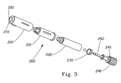
- Disposable cartridge 200 may contain a variety of product, including but not limited to, cosmetics, skin creams, and skin lotions.
- the product in disposable cartridge 200 may be positively displaced (discussed infra) and powered by gearbox/motor component 10.
- Gearbox/motor component 10 may be fixed onto a left or first housing 30.
- the gearbox/motor component 10 can be affixed into place mechanically, adhesively, or by any other suitable technique.
- Gearbox/motor component 10 preferably comprises a precision motor 10a connected to a gearbox 10b.
- Power source 20 provides power to the device.
- An example of a suitable power source 20 includes, but is not limited to, two "AAA" type batteries.
- the power source 20 provides power to the device through the control circuit 60, the high voltage power supply 40, and then the high voltage contact 50, which contacts the disposable cartridge 200.
- High voltage power supply 40 is powered and controlled by control circuit 60 (discussed infra).
- Power-on switch 80 permits the user to cause an interruption between power source 20 and circuit control 60.
- Power-on switch 80 is designed such that voltage is supplied to the remainder of the circuit only when switch 80 is in the "ON" or closed position. Apply switch 70 permits the user to selectively activate motor 10a, thereby activating the delivery and spraying of the product.
- Gearbox/motor component 10 has a driver 90 fastened to a shaft (not shown in Fig 1 & 2 , see Fig 3 ) of gearbox 10b, for example, with a set screw (not shown).
- Driver 90 has a number of protruding fingers, for example, three, which can fit into the matching recesses on the back of actuator 240.
- a first aspect of this invention is directed at defining a spark gap 300 between the charging location 310 (e.g. a point within the open chamber of disposable cartridge 200 and also near high voltage electrode 210) and the nozzle exit orifice 280 (e.g. point at which spray exits device 5).
- the charging location 310 e.g. a point within the open chamber of disposable cartridge 200 and also near high voltage electrode 2
- the nozzle exit orifice 280 e.g. point at which spray exits device 5.
- the preferred spacing between the charging location 310 and nozzle exit orifice 280 is governed by the following relationship : V o / d ⁇ 100 , 000 Where:
- disposable cartridge 200 has a conductive shield 210 which is positioned substantially around the outer perimeter of product reservoir 220.
- Conductive shield 210 may be constructed using conductive plastic (e.g. acrylonitrile butadiene styrene (ABS) filled with 10% carbon fibers), metal (e.g. aluminum) or any other suitable material.
- Conductive shield 210 may be formed as an integral part to cartridge insulator 260, such as through co-injection or two shot molding or any other manufacturing techniques. Alternatively, conductive shield 210 may be formed separately and then later connected to cartridge insulator 260 by any suitable technique, including but not limited to, force fitting.
- Actuator 240 is located at the non-discharge end of disposable cartridge 200.
- Actuator 240 may have internal threads (not shown) for passage of one end of a threaded shaft 250, and a snap bead 245 to snap into an open end of product reservoir 220.
- the opposite end of threaded shaft 250 can have a piston 230 which moves about.
- the threaded shaft 250 can thereby connect the piston 230 with actuator 240, such that piston 230 can slide along an inner surface of product reservoir 220, toward a nozzle 270, in response to the turning of actuator 240 by the gearbox/motor component 10. This movement of piston 230 can thus displace product from the product reservoir 220.
- Electrical shock in the form of a tactile discharge to the user is likely to occur when no product is located within spark gap 300.
- a condition can exist, for example, when the user is using a disposable cartridge 200 for the first time (ie: before spark gap 300 is filled with product during a first product application).
- the above mentioned relationship is optimized (ie: minimize the quotient value) to prevent exceeding the break-down potential of air when a grounded object such as a the operator's finger is brought within immediate proximity of nozzle exit orifice 280.
- electrical shock in the form of a tactile discharge to the user is also likely to occur when product fills spark gap 300.
- a condition exists, for example, when the user has already fully dispensed product from disposable cartridge 200 and thus the product pathway is full.
- the above mentioned relationship may need to be set at a quotient value less than 100,000 to prevent an electrical shock from occur.
- the actual reduced quotient value will be dependent upon the conductivity of the conductive fluid (ie: higher conductivity value of the fluid will require a lower quotient value).
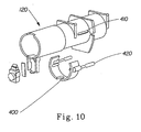
- Electrode cover 400 is added. Electrode cover 400 is designed such that it substantially conceals high voltage contact 50 when disposable cartridge 200 is removed from device 5. Electrode cover 400 may be connected to insert sleeve 110. Insert sleeve 110 may house disposable cartridge 200. Electrode cover 400 is movably connected within slide channel 410. Bias springs 420 are positioned such that when no disposable cartridge 200 is within insert sleeve 110, bias springs 420 slide electrode cover 400 in a normally closed position that shields high voltage contact 50.
- Electrode cover 400 When disposable cartridge 200 is placed within insert channel 110, electrode cover 400 is slid back in slide channel 410 to expose high voltage contact 50, such that it can then contact conductive shield 210 on disposable cartridge 200. Electrode cover 400 is of sufficient insulative quality so as to prevent electrical discharges from high voltage contact 50 through electrode cover 400 to a user.
- a further embodiment of electrode protection could also be in the form a high voltage electrode in the device positioned such that said high voltage electrode recesses when a cartridge is removed and makes proper contact with the cartridge electrode only when a cartridge is properly installed (not shown).
- Figure 5 shows an electrical schematic of one embodiment of an electrostatic spraying device.
- the power source 510 shown can be a battery or other power source known in the art.
- the power source can be one or more user replaceable battery such as two standard "AAA" batteries.
- the power source could be user-rechargeable cells, a non-user serviceable rechargeable power pack, or an external source (i.e. "line” supply).
- power source 510 can be separated from the rest of the circuit by a power switch 520.
- the power switch 520 can extend the active life of a self-contained power source 510 such as a battery.
- the power switch 520 can also add a margin of safety to a line-voltage power supply by supplying power to the remainder of the circuit only when the power switch 520 is closed.
- the power switch 520 can be a toggle switch that is able to maintain its setting until a later actuation. When switch 520 is turned to the "on" position, power is supplied to the DC/DC Converter 530.
- the DC/DC Converter 530 receives an input voltage supply from power source 510, for example, a nominal 3.0 volt supply from two conventional "AAA" type batteries, and converts that to a higher voltage signal such as a 5.0 volt supply.
- the DC/DC Converter 530 can be, for example, a 3 to 5 V DC converter available from Linear Technology Corporation (Part number LT1317BCMS8-TR).
- the DC/DC Converter 30 can also be used to send a signal to indicator 540. This signal can be either a portion of the supply signal from power source 10, or a portion of the output signal, for example 5.0 volts.
- the indicator 540 for example, can be an LED that emits light in the orange range of the visible electromagnetic (EM) spectrum.
- the indicator 540 can be arranged to emit visible light only when the power switch 520 is in the "on” position and sufficient voltage is supplied to the indicator 540 from DC/DC Converter 530.
- a user controlled apply switch 545 can be depressed or turned to the "on” position, depending on the type of switch employed, to complete the power supply circuit and provide power to the voltage regulator 550.
- the voltage regulator 550 can control the input voltage to a motor 560, if necessary.
- the nominal voltage output from the voltage regulator can be about 3.3 volts.
- the voltage regulator 550 can also send an output signal to the high voltage switch 570.
- the high voltage switch 570 for example, can be a transistor or diode element such as a transistor from NEC Corporation part number 2SA812.
- the high voltage switch 570 supplies power to the remaining high voltage generation circuitry in response to a signal from the voltage regulator 550.
- the high voltage switch 570 sends a signal to both high voltage control block 580 and a signal generator such as square wave generator 590.
- the high voltage control block 580 compares a signal from storage capacitor 610 and current limiter 670 to an internally set reference voltage. Depending upon the value of the feedback signal from storage capacitor 110 and/or a signal from the current limiter 670, the high voltage control block 580 will send either an "ON" or an "OFF" signal to the DC/DC converter 600.
- the high voltage control block 580 for example, can be an op-amp such as Toshiba Corporation part number TC75W57FU.
- the DC/DC converter 600 converts a lower input voltage to a higher output voltage.
- the DC/DC converter 600 can convert a nominal input voltage of about 5.0 volts to a higher nominal output voltage of about 25.0 volts.
- the output from the DC/DC converter 600 charges the storage capacitor 610.
- the storage capacitor 610 provides an input voltage to the primary coil of the high voltage transformer 620.
- the frequency of the higher voltage output of DC/DC converter 600 is controlled, as described in more detail later, by a feedback loop to ensure that a substantially constant supply, such as about a 25.0 volts supply, is available to the high voltage transformer 620 from the storage capacitor 610.
- the DC/DC converter 600 can be, for example, a DC/DC Converter from Toshiba Corporation such as part number TC75W57FU.
- the high voltage switch 570 can also send an "ON" signal to the square wave generator 590, which is also connected to the primary coil of the high voltage transformer 620. This results in about a 25.0 volt peak to peak AC pulses being generated through the primary coil of the high voltage transformer 620.
- the square wave generator 590 can be, for example, an op-amp element from Toshiba Corporation such as part number TC75W57FU.
- the turn ratio of the high voltage transformer 620 can be, for example, about 100:1 such that an input voltage of about 25.0 volt at the primary coil would result in about a 2.5 kV (2500 volt) output voltage from the secondary coil.
- the output voltage from the high voltage transformer 620 can then be supplied to a voltage multiplier 630.
- the voltage multiplier 630 rectifies the output signal from the high voltage transformer 620 and multiplies it to provide a higher voltage DC output voltage. If the output voltage of the high voltage transformer 620 is about a 2.5 kV AC signal, for example, the voltage multiplier 630 could rectify this signal and multiply it to provide a higher voltage DC output such as a 14.0 kV DC output voltage.
- the voltage multiplier 630 can be a six stage Cockroft-Walton diode charge pump. A stage for a Cockroft-Walton diode charge pump is commonly defined as the combination of one capacitor and one diode within the circuit.
- the number of stages needed with a voltage multiplier is a function of the magnitude of the input AC voltage source and is dependent upon the required output voltage.
- the high voltage transformer 620 and the voltage multiplier 630 can be encapsulated in a sealant such as a silicon sealant such as one available from Shin-Etsu Chemical Company, Ltd. as part number KE1204(A.B)TLV.
- a sealant such as a silicon sealant such as one available from Shin-Etsu Chemical Company, Ltd. as part number KE1204(A.B)TLV.
- a current limiting resistor 640 can be located between the output of high voltage multiplier 630 and the high voltage electrode 650.
- the current limiting resistor 640 can be used to limit the current output from the high voltage multiplier 630 available to the high voltage electrode 650.
- the current limiting resistor 640 could be, for example, about 20 megaohms.
- One skilled in the art would recognize, however, that if a higher output current is desired, then a current limiting resistor with a lower resistance would be desired. Conversely, if a lower output current is desired, then a current limiting resistor with a higher resistance would be desired.
- the high voltage electrode 650 can be made from a suitable metal or conductive plastic, such as acrylonitrile butadiene styrene (ABS) filled with 10% carbon fibers.
- a bleeder resistor 660 which is described in more detail below, can also be connected as shown in Figure 5 .
- the current limiter 670 is also connected to the output circuitry of the high voltage multiplier 630.
- a ground contact 680 can also be provided to establish a common ground between the circuitry of the electrostatic spraying device and the user in order to reduce the risk of shocking the user. Further, in personal care applications, the ground contact 680 can also prevent charge from building-up on the skin of the user as the charged particles accumulate on the skin of the user.
- the ground contact 680 can be integrated into apply switch 545 and/or substantially adjacent to apply switch 545 such that the user cannot energize the motor 560 and the high voltage supply circuitry without simultaneously grounding themselves to the device.
- the apply switch 545 can be made of metal and/or the ground contact can be a conductive contact or a grounding electrode can be located next to apply switch 545.
- a further aspect of this invention allows the electrostatic spray device to reduce after-spray.
- After-spray is defined as when the electrostatic spraying device momentarily continues to spray product after power has been shut down to the high voltage power supply.
- Electrostatic spray devices with integral high voltage power supplies typically use capacitor-diode ladders to step-up output voltage from a primary high voltage transformer.
- One suitable capacitor-diode ladder is a Cockroft-Walton type diode charge pump.
- Capacitors are also used in electrostatic spray circuitry to improve the quality in the high voltage output and to reduce variations or noise.
- the capacitors function as electrical storage elements and store the high voltage charge until the charge is dissipated such as through corona leakage to the atmosphere or a spark discharge to a point having a lower electrical potential (e.g., a shock to a user).
- This stored charge can continue to provide power to the high voltage electrode 650 and may create enough of a potential difference between the product and nearby surfaces to allow for the product to spray after the power has been cut off to the high voltage power supply until the charge in the capacitors is sufficiently dissipated.
- An after-spray condition is undesirable because the device continues to spray product after the user has turned off the device and the spray quality is inconsistent because the charge-to-mass ratio significantly varies.
- the desired charge-to-mass ratio is not maintained because there is not a consistent supply of high voltage current available to completely atomize the product into a spray.
- the charge stored within the device can partially atomize the product for a period of time while the charge dissipates to create an after-spray. Since the voltage supply to atomize the product is not constant, the charge-to-mass ratio of the resulting spray will vary resulting in the production of a spray that has varying spray quality.
- the after-spray condition can produce a spray at an unintended time and/or location, such as continuing to spray after the user has placed the device in a purse or storage cabinet. This can create an unexpected and undesirable mess.
- a high voltage resistor such as bleeder resistor 660 shown in Figure 5
- the bleeder resistor 660 can provide a path by which excess stored energy in the device, such as the energy stored in the capacitors within the voltage multiplier 630, can be dissipated in a relatively short period of time after the user has completed the spraying operation, thereby reducing the occurrence of after-spray.
- the bleeder resistor 660 should be selected to have a large enough resistance so that the impedance of bleeder resistor 660 will be significantly high when compared to the output current limiting resistor and the spray load so as to not dramatically effect the quality of spray or output of the high voltage generator during normal operation. If the value of bleeder resistor 660 is too low, bleeder resistor 660 will provide a path of lesser resistance than the resistance represented by the spraying operation. In this case bleeder resistor 160 will drain more current then desired during normal spraying operation. When the current passing through bleeder resistor 660 in normal spraying operation is too high, there will be insufficient current available for atomizing and charging the product.
- the bleeder resistor can further shorten the life of a portable power source such as a battery.
- the bleeder resistor 660 should, however, have a resistance low enough so as to allow for dissipation of stored energy in a relatively short period of time.
- the charge dissipated within ⁇ A is sufficient to reduce the charge within the device to a point where after-spray is reduced or eliminated.
- the time ⁇ A may not be sufficient time to drain enough charge to reduce or completely eliminate after-spray.
- the designer may desire to drain the entire stored charge from the within the device.
- a mechanical switch 690 can be provided to reduce the effects of after-spray.
- the high voltage mechanical switch 690 performs a similar function as bleeder resistor 660 with the exception that the high voltage mechanical switch 690 is not an active circuit element during normal spraying operation. Rather, the mechanical switch is arranged so that during normal spraying operation the switch is in the open position and is not drawing any current. However, when the user intends to cease the spraying operation and de-energizes the device, the high voltage mechanical switch 690 is shifted from the open position to the closed position so that a conductive path exists between the output electrode directly to the grounded side of the device circuit, thereby providing a nearly instantaneous release for any stored charge within the device.
- the conductive path to ground does not need to include a resistor and allows for a faster discharge rate. Further, the conductive path is only available when the device is de-energized, i.e., in the off position, and does not interfere with normal spraying operation by draining energy from the high voltage electrode 650 and will not require the high voltage generating circuitry to generate excess power to compensate for power losses associated with the bleeder resistor 660.
- the device comprises a high voltage electrical switch 700, such as a transistor, in place of bleeder resistor 660 shown in Figure 5 .
- a high voltage electrical switch 700 such as a transistor
- the switch is in the open position and the conductive path to a point of lower potential of the circuitry is not active.
- the switch is closed and the conductive path to a point of the circuit having a lower potential is then available to drain the stored charge in the device.
- the high voltage electrical switch 700 can provide a lower resistance than the bleeder resistor 660 and, thus, allows for a quicker discharge of the stored charge in the device.
- the high voltage electrical switch 700 further provides a conductive path that is only available when the device is de-energized, i.e., in the off position, and does not interfere with normal spraying operation by draining energy from the high voltage electrode 650 and will not require the high voltage generating circuitry to generate excess power to compensate for power losses associated with the bleeder resistor 660.
- Figure 6 or Figure 7 may also include a bleeder resistor 660 such as shown in Figure 8 .
- the bleeder resistor 660 can be connected to either the high voltage mechanical switch 690 or the high voltage electrical switch 700 as shown in Figure 8 .
- a bleeder resistor and/or mechanical or electrical switches may be arranged in other configurations.
- Figure 9 shows one alternative configuration in which the bleeder resistor 660 is connected between the voltage multiplier 630 and the current limiting resistor 670 and a point at a lower potential.
- Yet another aspect of this invention is providing current limiting control circuitry to control the output current from the high voltage supply means.
- Current limiter 570 monitors the output current at the first stage of voltage multiplier 530.
- Current limiter can be an op-amp element of the type, for example, from Toshiba Corporation, part number TC75W57FU.
- Current limiter tracks the current in ground return loop of voltage multiplier 630.
- current limiter 670 sends an override signal to high voltage control block 580.
- the override signal sent to high voltage control block 580 overrides the signal from ground return loop 630 and changes the output from to DC/DC converter 600 from "ON" to "OFF", thereby preventing a further increase in current through voltage multiplier 630.
- the signal from current limiter 670 to high voltage control block 680 changes, thereby allowing high voltage control block 580 to resume monitoring feedback loop 710 and sending an "ON" signal to DC/DC converter 600.
- the need for current limiter 670 is very important, for example, when using a circuit with an adjustable output power supply.
- high voltage control block 580 is designed to monitor the voltage output of the device, and when needed (e.g.
Claims (9)
- Elektrostatische Sprühvorrichtung (5), die so gestaltet und aufgebaut ist, dass ein Produkt elektrostatisch geladen und von einer Zufuhr an einen Dispersionspunkt abgegeben wird, wobei die Vorrichtung gekennzeichnet ist durch:einen Behälter (220), der so gestaltet ist, dass er die Produktzufuhr enthält;eine Düse (270), um das Produkt fein zu verteilen, wobei die Düse am Dispersionspunkt angeordnet ist; wobei die Düse eine Ausgangsöffnung (280) aufweist;einen Kanal, der zwischen dem Behälter (220) und der Düse (270) angeordnet ist, wobei der Kanal die elektrostatische Ladung des Produkts erlaubt, wenn das Produkt sich in dem Kanal bewegt;einen Mechanismus (240), um das Produkt von dem Behälter zu der Düse zu bewegen;eine Stromquelle (20), um eine elektrische Ladung bereitzustellen;eine Hochspannungszufuhr (40), wobei die Hochspannungszufuhr (40) elektrisch mit der Stromquelle (20) verbunden ist;einen Hochspannungskontakt (50), wobei der Hochspannungskontakt elektrisch mit der Hochspannungszufuhr (40) verbunden ist; undeine Hochspannungselektrode (210), wobei die Hochspannungselektrode (210) elektrisch mit der Hochspannungszufuhr (40) verbunden ist, wobei ein Teil der Hochspannungselektrode (210) zwischen dem Behälter (220) und der Düse (270) angeordnet ist, wobei die Hochspannungselektrode (210) das Produkt in dem Kanal an einem Ladeort elektrostatisch lädt;dadurch gekennzeichnet, dass der Abstand zwischen dem Ladeort und der Ausgangsöffnung der Düse von der folgenden Beziehung bestimmt ist:

worin:Vo = eine Ausgangsspannung der Hochspannungszufuhrd = linearer Abstand zwischen dem Ladeort und der Ausgangsöffnung der Düse. - Elektrostatische Sprühvorrichtung nach Anspruch 1, wobei die Beziehung Vo / d vorzugsweise weniger als 70.000 beträgt.
- Elektrostatische Sprühvorrichtung nach Anspruch 1, wobei die Beziehung Vo / d mehr bevorzugt weniger als 50.000 beträgt.
- Elektrostatische Sprühvorrichtung nach Anspruch 1, wobei "Vo" vorzugsweise im Bereich von 10.000 Volt bis 20.000 Volt liegt.
- Elektrostatische Sprühvorrichtung nach Anspruch 1, wobei "d" vorzugsweise im Bereich von 0,0025-0,0127 m (0,1 Zoll bis 0,5 Zoll) liegt.
- Elektrostatische Sprühvorrichtung (5), die so gestaltet und aufgebaut ist, dass ein Produkt elektrostatisch geladen und von einer Zufuhr an einen Dispersionspunkt abgegeben wird, wobei die Vorrichtung gekennzeichnet ist durch:einen Behälter (220), der so gestaltet ist, dass er die Produktzufuhr enthält;eine Düse (270), um das Produkt fein zu verteilen, wobei die Düse am Dispersionspunkt angeordnet ist; wobei die Düse eine Ausgangsöffnung (280) aufweist;einen Kanal, der zwischen dem Behälter (220) und der Düse (270) angeordnet ist, wobei der Kanal die elektrostatische Ladung des Produkts erlaubt, wenn das Produkt sich in dem Kanal bewegt;einen Mechanismus (240), um das Produkt von dem Behälter zu der Düse zu bewegen;eine Stromquelle (20), um eine elektrische Ladung bereitzustellen;eine Hochspannungszufuhr (40), wobei die Hochspannungszufuhr (40) elektrisch mit der Stromquelle verbunden ist;einen Hochspannungskontakt (50), wobei der Hochspannungskontakt elektrisch mit der Hochspannungszufuhr (40) verbunden ist;eine Hochspannungselektrode (210), wobei die Hochspannungselektrode elektrisch mit der Hochspannungszufuhr (40) verbunden ist, wobei ein Teil der Hochspannungselektrode (210) zwischen dem Behälter (220) und der Düse (270) angeordnet ist, wobei die Hochspannungselektrode (210) das Produkt in dem Kanal an einem Ladeort elektrostatisch lädt; unddadurch gekennzeichnet, dass eine bewegliche Elektrodenabdeckung (400) den Hochspannungskontakt (50) im Wesentlichen verdeckt, wenn die Einwegkartusche (200) aus der Vorrichtung ausgebaut ist.
- Elektrostatische Sprühvorrichtung nach Anspruch 6, wobei die Elektrodenabdeckung (400) mit einer Einsatzhülse (110) verbunden und in ihr beweglich ist.
- Elektrostatische Sprühvorrichtung nach Anspruch 7, wobei mindestens eine Vorspannungsfeder verwendet wird, um die Elektrodenabdeckung (400) in eine geschlossene Position zu bringen, wenn die Einwegkartusche (200) von der Vorrichtung ausgebaut ist.
- Elektrostatische Sprühvorrichtung (5), die so gestaltet und aufgebaut ist, dass ein Produkt elektrostatisch geladen und von einer Zufuhr an einen Dispersionspunkt abgegeben wird, wobei die Vorrichtung gekennzeichnet ist durch:einen Behälter (220), der so gestaltet ist, dass er die Produktzufuhr enthält;eine Düse (270), um das Produkt fein zu verteilen, wobei die Düse am Dispersionspunkt angeordnet ist; wobei die Düse eine Ausgangsöffnung (280) aufweist;einen Kanal, der zwischen dem Behälter (220) und der Düse (270) angeordnet ist, wobei der Kanal die elektrostatische Ladung des Produkts erlaubt, wenn das Produkt sich in dem Kanal bewegt;einen Mechanismus (240), um das Produkt von dem Behälter zu der Düse zu bewegen;eine Stromquelle (20), um eine elektrische Ladung bereitzustellen;eine Hochspannungszufuhr (40), wobei die Hochspannungszufuhr elektrisch mit der Stromquelle (20) verbunden ist;einen Hochspannungskontakt (50), wobei der Hochspannungskontakt elektrisch mit der Hochspannungszufuhr (40) verbunden ist; undeine Hochspannungselektrode (210), wobei die Hochspannungselektrode (210) elektrisch mit der Hochspannungszufuhr (40) verbunden ist, wobei ein Teil der Hochspannungselektrode (210) zwischen dem Behälter (220) und der Düse (270) angeordnet ist, wobei die Hochspannungselektrode (210) das Produkt in dem Kanal an einem Ladeort elektrostatisch lädt;dadurch gekennzeichnet, dass die Hochspannungselektrode sich zurückzieht, wenn die Einwegkartusche von der Vorrichtung ausgebaut wird, und die Hochspannungselektrode wieder erscheint, wenn die Einwegkartusche in die Vorrichtung eingesetzt wird.
Applications Claiming Priority (3)
| Application Number | Priority Date | Filing Date | Title |
|---|---|---|---|
| US09/759,550 US6682004B2 (en) | 1999-08-18 | 2001-01-12 | Electrostatic spray device |
| US759550 | 2001-01-12 | ||
| PCT/US2002/000698 WO2002055212A1 (en) | 2001-01-12 | 2002-01-11 | Electrostatic spray device |
Publications (2)
| Publication Number | Publication Date |
|---|---|
| EP1349669A1 EP1349669A1 (de) | 2003-10-08 |
| EP1349669B1 true EP1349669B1 (de) | 2008-07-23 |
Family
ID=25056075
Family Applications (1)
| Application Number | Title | Priority Date | Filing Date |
|---|---|---|---|
| EP02708992A Expired - Lifetime EP1349669B1 (de) | 2001-01-12 | 2002-01-11 | Elektrostatische sprühvorrichtung |
Country Status (11)
| Country | Link |
|---|---|
| US (1) | US6682004B2 (de) |
| EP (1) | EP1349669B1 (de) |
| JP (2) | JP3959026B2 (de) |
| KR (1) | KR20030071812A (de) |
| CN (1) | CN1256184C (de) |
| AT (1) | ATE401964T1 (de) |
| CA (1) | CA2432229A1 (de) |
| CZ (1) | CZ20031492A3 (de) |
| DE (1) | DE60227778D1 (de) |
| MX (1) | MXPA03006257A (de) |
| WO (1) | WO2002055212A1 (de) |
Cited By (1)
| Publication number | Priority date | Publication date | Assignee | Title |
|---|---|---|---|---|
| US11207510B2 (en) | 2018-11-19 | 2021-12-28 | Octet Medical, Inc. | Apparatus for applying a treatment solution to a treatment site |
Families Citing this family (29)
| Publication number | Priority date | Publication date | Assignee | Title |
|---|---|---|---|---|
| US6814318B2 (en) | 1999-08-18 | 2004-11-09 | The Procter & Gamble Company | Disposable cartridge for electrostatic spray device |
| US20070031607A1 (en) * | 2000-12-19 | 2007-02-08 | Alexander Dubson | Method and apparatus for coating medical implants |
| US20020084178A1 (en) * | 2000-12-19 | 2002-07-04 | Nicast Corporation Ltd. | Method and apparatus for manufacturing polymer fiber shells via electrospinning |
| US20040030377A1 (en) * | 2001-10-19 | 2004-02-12 | Alexander Dubson | Medicated polymer-coated stent assembly |
| AU2002241222A1 (en) * | 2001-03-20 | 2002-10-03 | Nicast Ltd. | Portable electrospinning device |
| DE60320535T2 (de) * | 2002-02-25 | 2009-06-10 | The Procter & Gamble Company, Cincinnati | Elektrostatische sprühvorrichtung |
| WO2005075091A1 (en) * | 2004-02-09 | 2005-08-18 | Matsushita Electric Works, Ltd. | Electrostatic spraying device |
| WO2005075093A1 (en) * | 2004-02-09 | 2005-08-18 | Matsushita Electric Works, Ltd. | Electrostatic spraying device |
| WO2005075090A1 (en) * | 2004-02-09 | 2005-08-18 | Matsushita Electric Works, Ltd. | Electrostatic spraying device |
| EP1748850B1 (de) * | 2004-02-09 | 2008-07-16 | Matsushita Electric Works, Ltd. | Elektrostatisches sprühgerät |
| US8197234B2 (en) * | 2004-05-25 | 2012-06-12 | California Institute Of Technology | In-line actuator for electromagnetic operation |
| US7867141B2 (en) * | 2004-07-21 | 2011-01-11 | Panasonic Electric Works Co., Ltd. | Physical activity measuring system |
| EP1848542A1 (de) * | 2005-02-11 | 2007-10-31 | Battelle Memorial Institute | Ehd-aerosol-abgabevorrichtung und sprühverfahren |
| JP2008535534A (ja) * | 2005-02-17 | 2008-09-04 | ナイキャスト リミテッド | 膨張可能な医療装置 |
| US8960575B2 (en) * | 2009-01-13 | 2015-02-24 | Finishing Brands Holdings Inc. | Electrostatic spray system and method |
| CN101875033A (zh) * | 2009-04-30 | 2010-11-03 | 沈为国 | 一种静电喷雾器用安全强化感应电极 |
| US8893990B2 (en) * | 2010-02-26 | 2014-11-25 | Finishing Brands Holdings Inc. | Electrostatic spray system |
| PE20121059A1 (es) | 2010-10-07 | 2012-08-09 | Alamos Vasquez Adolfo | Nebulizadora electrostatica de alto caudal, capaz de imprimir una alta carga electrostatica en la boquilla a la gota a nebulizar, de gran simpleza de construccion |
| US8833679B2 (en) | 2010-11-24 | 2014-09-16 | Finishing Brands Holdings, Inc. | Electrostatic spray system with grounding teeth |
| JP5623931B2 (ja) * | 2011-02-08 | 2014-11-12 | 旭サナック株式会社 | 静電塗装装置 |
| US8622324B2 (en) * | 2011-10-14 | 2014-01-07 | Zyw Corporation | VOC-less electrostatic fluid dispensing apparatus |
| CN110743720B (zh) | 2014-09-04 | 2022-04-29 | 胜利创新公司 | 静电喷雾器装置 |
| JP6112130B2 (ja) * | 2015-03-25 | 2017-04-12 | トヨタ自動車株式会社 | 静電ノズル、吐出装置及び半導体モジュールの製造方法 |
| WO2017112781A1 (en) | 2015-12-21 | 2017-06-29 | Victory Innovations Company | Electrostatic fluid delivery backpack system |
| CN112055652B (zh) | 2017-11-21 | 2023-11-28 | 花王株式会社 | 电纺丝装置及其系统和方法 |
| US11583487B2 (en) | 2018-08-09 | 2023-02-21 | Kao Corporation | Method for producing coating |
| WO2022160067A1 (en) * | 2021-01-31 | 2022-08-04 | Siozen Inc. | Contactless electrical connection for portable electrostatic sprayer apparatus |
| JP7141564B1 (ja) * | 2022-04-28 | 2022-09-22 | カーライル フルイド テクノロジーズ エルエルシー | 静電塗装装置 |
| WO2023171764A1 (ja) * | 2022-03-11 | 2023-09-14 | 花王株式会社 | 静電噴出装置 |
Family Cites Families (57)
| Publication number | Priority date | Publication date | Assignee | Title |
|---|---|---|---|---|
| US2159894A (en) | 1937-02-04 | 1939-05-23 | Posie L Hines | Sprayer |
| US2629516A (en) | 1951-10-02 | 1953-02-24 | Lucretia E Badham | Combination liquid pistol and spotlight |
| BE525410A (de) | 1952-12-30 | |||
| FR2127433A5 (en) | 1971-03-01 | 1972-10-13 | Tech Cuir Centre | Electrostatic spraying process and machine - for finishing of leathers |
| GB1454395A (en) | 1973-07-26 | 1976-11-03 | Volstatic Coatings Ltd | Power supply voltage control circuit |
| US4095962A (en) * | 1975-03-31 | 1978-06-20 | Richards Clyde N | Electrostatic scrubber |
| US4122845A (en) | 1975-09-30 | 1978-10-31 | Bowles Fluidics Corporation | Personal care spray device |
| US4194696A (en) | 1976-07-14 | 1980-03-25 | Nordson Corporation | Electrostatic spray coating gun |
| US4079894A (en) | 1976-07-14 | 1978-03-21 | Nordson Corporation | Electrostatic spray coating gun |
| US4331298A (en) | 1977-03-02 | 1982-05-25 | Ransburg Corporation | Hand-held coating-dispensing apparatus |
| US4258073A (en) | 1978-03-02 | 1981-03-24 | Payne John M | Taking of finger prints |
| BE868443A (fr) | 1978-06-26 | 1978-12-27 | Staar Dev Cy S A | Systeme de conditionnement/distributeur pour doses uniques |
| SU867927A1 (ru) | 1979-04-02 | 1981-09-30 | Орловский научно-исследовательский институт легкого машиностроения | Камера дл покрывного крашени кожи в электростатическом поле |
| BE882449A (fr) | 1980-03-26 | 1980-07-16 | Ransburg Japan Ltd | Procede de revetement electrostatique et dispositif rotatif d'atomisation de peinture pour la mise en oeuvre de ce procede |
| BE882450A (fr) | 1980-03-26 | 1980-07-16 | Ransburg G M B H | Dispositif de dispersion electrostatique en gerbe de substance de revetement |
| EP0057324B1 (de) | 1981-01-30 | 1986-05-07 | Imperial Chemical Industries Plc | Verfahren und Vorrichtung zum Versprühen von Emulsionen |
| EP0096731A1 (de) | 1982-06-09 | 1983-12-28 | Gabriel Bernaz | Apparat zur ästhetischen und elektrotherapeutischen Pflege und Zerstäubervorrichtung |
| GB2128900B (en) | 1982-10-29 | 1985-11-20 | Theoktiste Christofidis | Ionising spray |
| GB8305816D0 (en) | 1983-03-02 | 1983-04-07 | Ici Plc | Containers |
| EP0120633B1 (de) | 1983-03-25 | 1988-12-14 | Imperial Chemical Industries Plc | Zerstäubungseinrichtung |
| US5229105A (en) | 1986-05-28 | 1993-07-20 | Donald Basiliere | Multi-active skin preparation |
| US4907727A (en) | 1988-10-31 | 1990-03-13 | Illinois Tool Works, Inc. | Dispensing device having improved plunger assemblies |
| US4971257A (en) * | 1989-11-27 | 1990-11-20 | Marc Birge | Electrostatic aerosol spray can assembly |
| US5105984A (en) | 1990-06-27 | 1992-04-21 | Kazimir Charles E | Paste tube dispenser and method for making same |
| EP0468735B1 (de) | 1990-07-25 | 1995-05-03 | Imperial Chemical Industries Plc | Elektrostatische Sprühmethode |
| EP0468736B1 (de) | 1990-07-25 | 1997-03-19 | Imperial Chemical Industries Plc | Elektrostatische Sprühvorrichtung und Verfahren |
| GB9023339D0 (en) | 1990-10-26 | 1990-12-05 | Ici Plc | Dispensing of fluids |
| DK0486198T3 (da) | 1990-11-12 | 2001-06-18 | Procter & Gamble | Sprøjteindretning |
| US5296681A (en) | 1991-01-15 | 1994-03-22 | Gunter Tschauder | Apparatus for hot moistening face-towels |
| GB9101812D0 (en) | 1991-01-28 | 1991-03-13 | Morgan Crucible Co | Dispensing of fluids |
| ES2158844T3 (es) | 1991-03-01 | 2001-09-16 | Procter & Gamble | Pulverizacion de liquidos. |
| GB9115278D0 (en) | 1991-07-15 | 1991-08-28 | Unilever Plc | Liquid spraying apparatus and method |
| GB9115277D0 (en) | 1991-07-15 | 1991-08-28 | Unilever Plc | Spraying system |
| GB9115275D0 (en) | 1991-07-15 | 1991-08-28 | Unilever Plc | Colour cosmetic spray system |
| GB9115279D0 (en) | 1991-07-15 | 1991-08-28 | Unilever Plc | Hair and scalp treatment system |
| GB9115276D0 (en) | 1991-07-15 | 1991-08-28 | Unilever Plc | Skin treatment system |
| CA2076488A1 (en) | 1991-09-27 | 1993-03-28 | James A. Quinn | Continuous monitoring electrostatic discharge system |
| DE4138763A1 (de) | 1991-11-26 | 1993-05-27 | Basf Ag | Verwendung von homo- oder copolymerisaten auf basis von quaternisierten 1-vinylimidazolen als organische polyelektrolyte |
| US5531384A (en) | 1992-06-18 | 1996-07-02 | Greene; Robert H. | Spray gun |
| JP3100783B2 (ja) | 1992-10-15 | 2000-10-23 | キユーピー株式会社 | ホスファチジルコリンおよびその製造方法 |
| GB9224191D0 (en) | 1992-11-18 | 1993-01-06 | Unilever Plc | Cosmetic delivery system |
| JP3655305B2 (ja) | 1992-11-23 | 2005-06-02 | エスティー ローダー インコーポレーテッド | 自己日焼け化粧料組成物及びそれを使用する方法 |
| GB2273673A (en) | 1992-12-22 | 1994-06-29 | Unilever Plc | Dental active delivery system |
| GB2273872A (en) | 1992-12-22 | 1994-07-06 | Unilever Plc | A method of treating skin |
| AU7017894A (en) | 1993-05-26 | 1994-12-20 | Procter & Gamble Company, The | Solid cosmetics having moisturizing effect |
| US5674481A (en) | 1993-06-24 | 1997-10-07 | Wahi; Ashok L. | Electrostatically charged nasal topical application product |
| US5468488A (en) | 1993-06-24 | 1995-11-21 | Wahi; Ashok L. | Electrostatically charged nasal application product and method |
| AU707149B2 (en) | 1994-04-29 | 1999-07-01 | Procter & Gamble Company, The | Spraying devices |
| CH688080A5 (de) | 1994-09-29 | 1997-05-15 | Kwc Ag | Brause mit einem Handgriff und einem mittels eines Handhebels betaetigbaren Absperrorgan. |
| GB9420511D0 (en) | 1994-10-11 | 1994-11-23 | Ici Plc | High voltage generator |
| WO1996010459A2 (en) | 1994-10-04 | 1996-04-11 | Imperial Chemical Industries Plc | Electrostatic spraying of particulate material |
| GB9511514D0 (en) | 1995-06-07 | 1995-08-02 | Ici Plc | Electrostatic spraying |
| CN1136821C (zh) | 1996-03-11 | 2004-02-04 | 普罗克特和甘保尔公司 | 静电手消毒装置及方法 |
| GB9622623D0 (en) | 1996-10-30 | 1997-01-08 | Ici Plc | Dispensing devices |
| JPH10146216A (ja) | 1996-11-18 | 1998-06-02 | Shiseido Co Ltd | 化粧用塗布具 |
| US6311903B1 (en) * | 1999-08-18 | 2001-11-06 | The Procter & Gamble Company | Hand-held electrostatic sprayer apparatus |
| US6318647B1 (en) * | 1999-08-18 | 2001-11-20 | The Procter & Gamble Company | Disposable cartridge for use in a hand-held electrostatic sprayer apparatus |
-
2001
- 2001-01-12 US US09/759,550 patent/US6682004B2/en not_active Expired - Lifetime
-
2002
- 2002-01-11 CN CNB028035496A patent/CN1256184C/zh not_active Expired - Lifetime
- 2002-01-11 KR KR10-2003-7009345A patent/KR20030071812A/ko active IP Right Grant
- 2002-01-11 AT AT02708992T patent/ATE401964T1/de not_active IP Right Cessation
- 2002-01-11 DE DE60227778T patent/DE60227778D1/de not_active Expired - Fee Related
- 2002-01-11 CZ CZ20031492A patent/CZ20031492A3/cs unknown
- 2002-01-11 CA CA002432229A patent/CA2432229A1/en not_active Abandoned
- 2002-01-11 JP JP2002555934A patent/JP3959026B2/ja not_active Expired - Lifetime
- 2002-01-11 MX MXPA03006257A patent/MXPA03006257A/es unknown
- 2002-01-11 EP EP02708992A patent/EP1349669B1/de not_active Expired - Lifetime
- 2002-01-11 WO PCT/US2002/000698 patent/WO2002055212A1/en active IP Right Grant
-
2007
- 2007-02-02 JP JP2007024746A patent/JP2007111699A/ja not_active Withdrawn
Cited By (1)
| Publication number | Priority date | Publication date | Assignee | Title |
|---|---|---|---|---|
| US11207510B2 (en) | 2018-11-19 | 2021-12-28 | Octet Medical, Inc. | Apparatus for applying a treatment solution to a treatment site |
Also Published As
| Publication number | Publication date |
|---|---|
| CZ20031492A3 (cs) | 2003-11-12 |
| JP3959026B2 (ja) | 2007-08-15 |
| US20010020652A1 (en) | 2001-09-13 |
| CA2432229A1 (en) | 2002-07-18 |
| JP2007111699A (ja) | 2007-05-10 |
| KR20030071812A (ko) | 2003-09-06 |
| CN1256184C (zh) | 2006-05-17 |
| US6682004B2 (en) | 2004-01-27 |
| CN1484549A (zh) | 2004-03-24 |
| JP2004517716A (ja) | 2004-06-17 |
| DE60227778D1 (de) | 2008-09-04 |
| MXPA03006257A (es) | 2003-09-22 |
| ATE401964T1 (de) | 2008-08-15 |
| EP1349669A1 (de) | 2003-10-08 |
| WO2002055212A1 (en) | 2002-07-18 |
Similar Documents
| Publication | Publication Date | Title |
|---|---|---|
| EP1349669B1 (de) | Elektrostatische sprühvorrichtung | |
| US7712687B2 (en) | Electrostatic spray device | |
| EP0626208B1 (de) | Stromversorgung für eine elektrostatische Sprühpistole | |
| KR100482930B1 (ko) | 핸드-헬드 정전 분무장치 | |
| KR100484360B1 (ko) | 핸드헬드 정전 분무 장치용 1 회용 카트리지 | |
| JP3384811B2 (ja) | 静電噴霧装置、静電噴霧装置の使用方法及び静電噴霧方法 | |
| US5184778A (en) | Electrostatic spraying apparatus | |
| EP0789626B1 (de) | Sprühvorrichtung | |
| KR100324980B1 (ko) | 광전스위치 | |
| AU2002243503A1 (en) | Electrostatic spray device | |
| AU2002243502A1 (en) | Electrostatic spray device |
Legal Events
| Date | Code | Title | Description |
|---|---|---|---|
| PUAI | Public reference made under article 153(3) epc to a published international application that has entered the european phase |
Free format text: ORIGINAL CODE: 0009012 |
|
| 17P | Request for examination filed |
Effective date: 20030718 |
|
| AK | Designated contracting states |
Kind code of ref document: A1 Designated state(s): AT BE CH CY DE DK ES FI FR GB GR IE IT LI LU MC NL PT SE TR |
|
| AX | Request for extension of the european patent |
Extension state: AL LT LV MK RO SI |
|
| 17Q | First examination report despatched |
Effective date: 20061208 |
|
| GRAP | Despatch of communication of intention to grant a patent |
Free format text: ORIGINAL CODE: EPIDOSNIGR1 |
|
| GRAS | Grant fee paid |
Free format text: ORIGINAL CODE: EPIDOSNIGR3 |
|
| GRAA | (expected) grant |
Free format text: ORIGINAL CODE: 0009210 |
|
| AK | Designated contracting states |
Kind code of ref document: B1 Designated state(s): AT BE CH CY DE DK ES FI FR GB GR IE IT LI LU MC NL PT SE TR |
|
| REG | Reference to a national code |
Ref country code: GB Ref legal event code: FG4D |
|
| REG | Reference to a national code |
Ref country code: CH Ref legal event code: EP |
|
| REG | Reference to a national code |
Ref country code: IE Ref legal event code: FG4D |
|
| REF | Corresponds to: |
Ref document number: 60227778 Country of ref document: DE Date of ref document: 20080904 Kind code of ref document: P |
|
| NLV1 | Nl: lapsed or annulled due to failure to fulfill the requirements of art. 29p and 29m of the patents act | ||
| PG25 | Lapsed in a contracting state [announced via postgrant information from national office to epo] |
Ref country code: PT Free format text: LAPSE BECAUSE OF FAILURE TO SUBMIT A TRANSLATION OF THE DESCRIPTION OR TO PAY THE FEE WITHIN THE PRESCRIBED TIME-LIMIT Effective date: 20081223 Ref country code: ES Free format text: LAPSE BECAUSE OF FAILURE TO SUBMIT A TRANSLATION OF THE DESCRIPTION OR TO PAY THE FEE WITHIN THE PRESCRIBED TIME-LIMIT Effective date: 20081103 Ref country code: NL Free format text: LAPSE BECAUSE OF FAILURE TO SUBMIT A TRANSLATION OF THE DESCRIPTION OR TO PAY THE FEE WITHIN THE PRESCRIBED TIME-LIMIT Effective date: 20080723 |
|
| PG25 | Lapsed in a contracting state [announced via postgrant information from national office to epo] |
Ref country code: FI Free format text: LAPSE BECAUSE OF FAILURE TO SUBMIT A TRANSLATION OF THE DESCRIPTION OR TO PAY THE FEE WITHIN THE PRESCRIBED TIME-LIMIT Effective date: 20080723 Ref country code: AT Free format text: LAPSE BECAUSE OF FAILURE TO SUBMIT A TRANSLATION OF THE DESCRIPTION OR TO PAY THE FEE WITHIN THE PRESCRIBED TIME-LIMIT Effective date: 20080723 |
|
| PG25 | Lapsed in a contracting state [announced via postgrant information from national office to epo] |
Ref country code: BE Free format text: LAPSE BECAUSE OF FAILURE TO SUBMIT A TRANSLATION OF THE DESCRIPTION OR TO PAY THE FEE WITHIN THE PRESCRIBED TIME-LIMIT Effective date: 20080723 |
|
| PG25 | Lapsed in a contracting state [announced via postgrant information from national office to epo] |
Ref country code: DK Free format text: LAPSE BECAUSE OF FAILURE TO SUBMIT A TRANSLATION OF THE DESCRIPTION OR TO PAY THE FEE WITHIN THE PRESCRIBED TIME-LIMIT Effective date: 20080723 |
|
| PLBE | No opposition filed within time limit |
Free format text: ORIGINAL CODE: 0009261 |
|
| STAA | Information on the status of an ep patent application or granted ep patent |
Free format text: STATUS: NO OPPOSITION FILED WITHIN TIME LIMIT |
|
| 26N | No opposition filed |
Effective date: 20090424 |
|
| PG25 | Lapsed in a contracting state [announced via postgrant information from national office to epo] |
Ref country code: MC Free format text: LAPSE BECAUSE OF NON-PAYMENT OF DUE FEES Effective date: 20090131 |
|
| REG | Reference to a national code |
Ref country code: CH Ref legal event code: PL |
|
| REG | Reference to a national code |
Ref country code: IE Ref legal event code: MM4A |
|
| PG25 | Lapsed in a contracting state [announced via postgrant information from national office to epo] |
Ref country code: CH Free format text: LAPSE BECAUSE OF NON-PAYMENT OF DUE FEES Effective date: 20090131 Ref country code: LI Free format text: LAPSE BECAUSE OF NON-PAYMENT OF DUE FEES Effective date: 20090131 Ref country code: DE Free format text: LAPSE BECAUSE OF NON-PAYMENT OF DUE FEES Effective date: 20090801 |
|
| REG | Reference to a national code |
Ref country code: FR Ref legal event code: ST Effective date: 20091030 |
|
| PG25 | Lapsed in a contracting state [announced via postgrant information from national office to epo] |
Ref country code: IE Free format text: LAPSE BECAUSE OF NON-PAYMENT OF DUE FEES Effective date: 20090111 Ref country code: SE Free format text: LAPSE BECAUSE OF FAILURE TO SUBMIT A TRANSLATION OF THE DESCRIPTION OR TO PAY THE FEE WITHIN THE PRESCRIBED TIME-LIMIT Effective date: 20081023 |
|
| PG25 | Lapsed in a contracting state [announced via postgrant information from national office to epo] |
Ref country code: FR Free format text: LAPSE BECAUSE OF NON-PAYMENT OF DUE FEES Effective date: 20090202 |
|
| PG25 | Lapsed in a contracting state [announced via postgrant information from national office to epo] |
Ref country code: GR Free format text: LAPSE BECAUSE OF FAILURE TO SUBMIT A TRANSLATION OF THE DESCRIPTION OR TO PAY THE FEE WITHIN THE PRESCRIBED TIME-LIMIT Effective date: 20081024 |
|
| PG25 | Lapsed in a contracting state [announced via postgrant information from national office to epo] |
Ref country code: IT Free format text: LAPSE BECAUSE OF NON-PAYMENT OF DUE FEES Effective date: 20090111 |
|
| PG25 | Lapsed in a contracting state [announced via postgrant information from national office to epo] |
Ref country code: LU Free format text: LAPSE BECAUSE OF NON-PAYMENT OF DUE FEES Effective date: 20090111 |
|
| PG25 | Lapsed in a contracting state [announced via postgrant information from national office to epo] |
Ref country code: TR Free format text: LAPSE BECAUSE OF FAILURE TO SUBMIT A TRANSLATION OF THE DESCRIPTION OR TO PAY THE FEE WITHIN THE PRESCRIBED TIME-LIMIT Effective date: 20080723 |
|
| PG25 | Lapsed in a contracting state [announced via postgrant information from national office to epo] |
Ref country code: CY Free format text: LAPSE BECAUSE OF FAILURE TO SUBMIT A TRANSLATION OF THE DESCRIPTION OR TO PAY THE FEE WITHIN THE PRESCRIBED TIME-LIMIT Effective date: 20080723 |
|
| PGFP | Annual fee paid to national office [announced via postgrant information from national office to epo] |
Ref country code: GB Payment date: 20201230 Year of fee payment: 20 |
|
| REG | Reference to a national code |
Ref country code: GB Ref legal event code: PE20 Expiry date: 20220110 |
|
| PG25 | Lapsed in a contracting state [announced via postgrant information from national office to epo] |
Ref country code: GB Free format text: LAPSE BECAUSE OF EXPIRATION OF PROTECTION Effective date: 20220110 |