EP1349422A2 - Abdeckvorrichtung für Hörgeräte - Google Patents
Abdeckvorrichtung für Hörgeräte Download PDFInfo
- Publication number
- EP1349422A2 EP1349422A2 EP03005839A EP03005839A EP1349422A2 EP 1349422 A2 EP1349422 A2 EP 1349422A2 EP 03005839 A EP03005839 A EP 03005839A EP 03005839 A EP03005839 A EP 03005839A EP 1349422 A2 EP1349422 A2 EP 1349422A2
- Authority
- EP
- European Patent Office
- Prior art keywords
- battery
- opening
- housing cover
- wire spring
- drawer
- Prior art date
- Legal status (The legal status is an assumption and is not a legal conclusion. Google has not performed a legal analysis and makes no representation as to the accuracy of the status listed.)
- Granted
Links
Images

Classifications
-
- H—ELECTRICITY
- H04—ELECTRIC COMMUNICATION TECHNIQUE
- H04R—LOUDSPEAKERS, MICROPHONES, GRAMOPHONE PICK-UPS OR LIKE ACOUSTIC ELECTROMECHANICAL TRANSDUCERS; ELECTRIC HEARING AIDS; PUBLIC ADDRESS SYSTEMS
- H04R25/00—Electric hearing aids
- H04R25/60—Mounting or interconnection of hearing aid parts, e.g. inside tips, housings or to ossicles
- H04R25/602—Mounting or interconnection of hearing aid parts, e.g. inside tips, housings or to ossicles of batteries
Definitions
- the present invention relates to a device for covering of a hearing aid housing with a housing cover, the an opening for the passage of a battery and an electronic module has and a battery charger by a Connecting element pivotally attached to the housing cover is to hold a battery.
- the present invention the locking system of the battery charger.
- So-called in-the-ear hearing aids have a housing that is individually adapted to the hearing aid wearer's ear canal is.
- the housing is on the opposite side of the eardrum Side of a housing cover applied.
- This case cover is usually firmly mounted on the housing.
- To the Loading the hearing aid with a battery comprises the hearing aid cover a special battery drawer that swivels on the Housing cover is attached.
- Such a battery charger is known from US-A-5784470. When removing The battery from the hearing aid becomes the battery charger from the Housing cover swung open so that the battery can be removed is led outside.
- BTE behind-the-ear hearing aids
- US-A-4831655 a cover for a battery compartment, which can be pivoted by a wire spring in the housing of the BTE device is stored.
- the wire spring is used for easy assembly and to ensure a certain robustness of the joint of the battery cover.
- An ITE device usually has integrated electronics on that with an amplifier, a microphone and more Components is populated.
- ITE devices available that have modular electronic assemblies.
- Such a module is for example from the patent US-A-5008943 known. The module will be removed there, however the entire housing cover is swung open.
- module inserts which are with springs or with Snap noses on the housing cover molded onto the module be locked.
- the object of the present invention is that Space requirement of an unloading and loading device for one To reduce battery and an electronic module of an ITE hearing aid.
- this object is achieved by a device for covering a hearing aid housing with a housing cover, the an opening for carrying a battery and has an electronic module, and a battery charger, the by a connecting element pivotable on the housing cover is attached to hold a battery, the battery charger covers the opening in every pivoting state in such a way that the electronics module cannot be passed through the opening is, and the connector with the battery charger of that Housing cover is removable, so that when the battery charger is removed the electronics module can be passed through the opening is.
- the connecting element advantageously consists of a Wire spring with two end sections and an elastic middle section, so the two end sections that are clamped in State lying on an axis, movable along this are.
- the middle section of the wire spring is there for example an arcuate, U-shaped, acute-angled one Wire section or the like.
- the end sections of the wire spring advantageously protrude through guides of the battery door and at the very end Guides or recordings of the housing cover. to Removing the battery door are the extreme ends of the end sections the wire spring from the guides of the housing cover to draw. The wire spring remains in the guides of the Battery drawer even when the battery drawer is off the case cover is removed.
- the electronic module is a defined one when installed Position, the opening through which the Electronic module is inserted into the hearing aid, at least have a guide groove.
- This also has the advantage that the module, for example, vertically out of the opening, that means through a defined movement, must be moved. Thereby can have a relatively small edge on the battery door the electronics module slipping out of the hearing aid prevent.
- the battery drawer advantageously provides a holder for the battery and a lid for the opening. In the closed Condition should be the opening of the battery door Completely close the protection of the electronics underneath.
- the swiveling battery drawer has a cheaper design next to the battery holder, a sound entry opening for an underlying microphone in the electronics module intended.
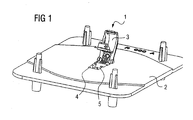
- FIG 1 is a battery door 1 in the opened state shown. In the case shown, it is on one Plastic plate 2 mounted, the one like the housing cover Hearing aid represents a plastic injection molded part.
- the Battery charger 1 has a battery holder 3 in which the Battery of a hearing aid is held. When closed is the battery holder including battery in an opening 4 pivoted. There is an electronic module in the opening 5 inserted. If the battery door 1 is swung down it covers the entire opening 4 including of the electronics module 5.
- Figure 2 shows the joint mechanism of the battery drawer 1 in detail.
- the joint around which the battery door 1 is pivotally mounted is consists of a wire spring 6, guides 7, which the battery door 1 are attached, and recordings 8, the the plate 2 are attached.
- the wire spring 6 is essentially ⁇ -shaped, wherein the ends of which correspond to the axis of the joint. The two ends respectively End sections are through the two guides 7 led into the respective recordings 8. This results in a Hinge for the battery door 1, the elastic hinge pin is given by the wire spring 6.
- the electronics module 5 is guided by guides 9 into the plate 2 inserted and thus fixed in this position. It is with it not possible that the electronic module 5 related to the Representation of Figure 2 slips forward. Because the electronics module 5 at its also on the representation of figure 2 related back has an extension, not shown, the under the joint with the wire spring 6 and the guides 7 is sufficient, the electronic module 5 cannot be removed from the Opening 4 are removed when the battery door 1 with the Joint is attached to the plate 2. Essential for this Function is not the extension not shown on Electronics module 5 but the fact that the battery charger 1 also reduces the opening 4 in the swung-open state, that the electronics module 5 is not through the opening 4 can be pushed. This ensures that the electronics module 5 fixed in the opening 4 without a special holder becomes.
- the Wire spring 6 for example, with tweezers at the narrow point of the ⁇ shape and compressed. Thereby the extreme ends of the wire spring from the receptacles 8 pulled, which removes the battery door from the plate 2 leaves. Then the electronics module from the Opening 4 can be removed.
- the electronics module 5 has a microphone, its outlet opening 10 is shown in Figure 2. So that opening 10 not in the closed state of the battery door 1 is covered by this, the battery drawer 1 has corresponding Set up a through opening 11. Because this opening 11 is arranged in the vicinity of the joint 6, 7, 8 the ⁇ -shape of the wire spring 6 also because cheap because with this wire shape the wire around the opening 11 is performed.
- the wire spring 6 in this way is dimensioned that only the Ends of the wire spring from the receptacles 8 but not from the Guides 7 are pulled. So that the wire spring 6 at the battery charge is not lost and the The battery drawer 1 can be installed in a few simple steps take place.
Landscapes
- Health & Medical Sciences (AREA)
- General Health & Medical Sciences (AREA)
- Neurosurgery (AREA)
- Otolaryngology (AREA)
- Physics & Mathematics (AREA)
- Engineering & Computer Science (AREA)
- Acoustics & Sound (AREA)
- Signal Processing (AREA)
- Battery Mounting, Suspending (AREA)
- Auxiliary Devices For And Details Of Packaging Control (AREA)
- Casings For Electric Apparatus (AREA)
- Charge And Discharge Circuits For Batteries Or The Like (AREA)
Abstract
Description
- Figur 1
- eine perspektivische Ansicht einer aufgeschwenkten Batterielade gemäß der vorliegenden Erfindung; und
- Figur 2
- eine perspektivische Detailansicht des Verschlussmechanismus der in Figur 1 dargestellten Batterielade.
Claims (8)
- Vorrichtung zum Abdecken eines Hörgerätegehäuses mitdadurch gekennzeichnet, dasseinem Gehäusedeckel (2), der eine Öffnung (4) zur Durchführung einer Batterie und eines Elektronikmoduls (5) aufweist, undeiner Batterielade (1), die durch ein Verbindungselement schwenkbar an dem Gehäusedeckel (2) angebracht ist, zur Aufnahme einer Batterie,
die Batterielade (1) in jedem Schwenkzustand die Öffnung (4) derart bedeckt, dass das Elektronikmodul (5) nicht durch die Öffnung (4) durchführbar ist, und das Verbindungselement mit der Batterielade (1) von dem Gehäusedeckel (2) abnehmbar ist, so dass bei abgenommener Batterielade (1) das Elektronikmodul (5) durch die Öffnung (4) durchführbar ist. - Vorrichtung nach Anspruch 1, wobei das Verbindungselement eine Drahtfeder (6) mit zwei Endabschnitten und einem dazwischenliegenden elastischen Mittelabschnitt umfasst.
- Vorrichtung nach Anspruch 2, wobei die Endabschnitte der Drahtfeder (6) im eingespannten Zustand auf einer Achse liegen und der Mittelabschnitt kreisbogenförmig, U-förmig oder dreiecksförmig ist.
- Vorrichtung nach Anspruch 2 oder 3, wobei die Endabschnitte der Drahtfeder (6) durch Führungen (7) der Batterielade (1) in Aufnahmen (8) des Gehäusedeckels (2) ragen.
- Vorrichtung nach Anspruch 4, wobei der Mittelabschnitt der Drahtfeder (6) derart verbiegbar ist, dass die Endabschnitte der Drahtfeder (6) vollständig aus den Aufnahmen (8) des Gehäusedeckels (2) gezogen werden können, um die Batterielade (1) von dem Gehäusedeckel (2) zu entnehmen.
- Vorrichtung nach einem der Ansprüche 1 bis 5, wobei die Öffnung (4) in dem Gehäusedeckel (2) mindestens eine Führungsnut (9) zur Führung des Elektronikmoduls (5) bei dessen Durchführung durch die Öffnung (4) umfasst.
- Vorrichtung nach einem der Ansprüche 1 bis 6, wobei die Batterielade (1) in einen Schließzustand schwenkbar ist, in dem sie die Öffnung (4) vollständig verdeckt.
- Vorrichtung nach einem der Ansprüche 1 bis 7, wobei die Batterielade (1) eine Schallöffnung (11) für ein in das Elektronikmodul (5) integriertes Mikrofon aufweist.
Applications Claiming Priority (2)
| Application Number | Priority Date | Filing Date | Title |
|---|---|---|---|
| DE10213847 | 2002-03-27 | ||
| DE10213847A DE10213847B4 (de) | 2002-03-27 | 2002-03-27 | Vorrichtung zum Abdecken eines Hörgerätegehäuses |
Publications (3)
| Publication Number | Publication Date |
|---|---|
| EP1349422A2 true EP1349422A2 (de) | 2003-10-01 |
| EP1349422A3 EP1349422A3 (de) | 2004-04-07 |
| EP1349422B1 EP1349422B1 (de) | 2006-01-25 |
Family
ID=27798216
Family Applications (1)
| Application Number | Title | Priority Date | Filing Date |
|---|---|---|---|
| EP03005839A Expired - Lifetime EP1349422B1 (de) | 2002-03-27 | 2003-03-14 | Abdeckvorrichtung für Hörgeräte |
Country Status (6)
| Country | Link |
|---|---|
| US (1) | US7039209B2 (de) |
| EP (1) | EP1349422B1 (de) |
| AT (1) | ATE316748T1 (de) |
| DE (2) | DE10213847B4 (de) |
| DK (1) | DK1349422T3 (de) |
| ES (1) | ES2256605T3 (de) |
Cited By (1)
| Publication number | Priority date | Publication date | Assignee | Title |
|---|---|---|---|---|
| EP1414270A3 (de) * | 2003-11-21 | 2004-05-26 | Phonak Ag | Gehäuse für eine Hörhilfe resp. ein Hörgerät |
Families Citing this family (6)
| Publication number | Priority date | Publication date | Assignee | Title |
|---|---|---|---|---|
| DK1404151T3 (da) * | 2002-09-25 | 2017-09-18 | Sivantos Gmbh | I øret bærbart høreapparat med et hus |
| AU2004317775B2 (en) * | 2004-03-31 | 2007-06-28 | Widex A/S | Component for a hearing aid and a hearing aid |
| US7443992B2 (en) * | 2004-04-15 | 2008-10-28 | Starkey Laboratories, Inc. | Method and apparatus for modular hearing aid |
| DE602005026060D1 (en) * | 2005-06-25 | 2011-03-03 | Siemens Audiologische Technik | Hörgeräteeinrichtung |
| DE102007055384A1 (de) * | 2007-11-20 | 2009-05-28 | Siemens Medical Instruments Pte. Ltd. | Hörhilfsgerät, insbesondere IO-Hörgerät |
| US9774964B2 (en) * | 2010-12-28 | 2017-09-26 | Sonova Ag | PIM housing |
Family Cites Families (9)
| Publication number | Priority date | Publication date | Assignee | Title |
|---|---|---|---|---|
| US4570290A (en) * | 1981-07-20 | 1986-02-18 | Hartwell Corporation | Hinge having a laterally outwardly extending flat spring |
| IT1209958B (it) * | 1985-05-09 | 1989-08-30 | Coselgi Spa | Perfezionamento nelle piastre esterne delle protesi acustiche intracanale |
| US4870688A (en) * | 1986-05-27 | 1989-09-26 | Barry Voroba | Mass production auditory canal hearing aid |
| DE8621021U1 (de) * | 1986-08-05 | 1988-01-21 | Siemens AG, 1000 Berlin und 8000 München | Scharnier für eine Klappe an einem Hörgerät |
| CA1274184A (en) * | 1986-10-07 | 1990-09-18 | Edward S. Kroetsch | Modular hearing aid with lid hinged to faceplate |
| US5347584A (en) * | 1991-05-31 | 1994-09-13 | Rion Kabushiki-Kaisha | Hearing aid |
| US5784470A (en) * | 1995-06-07 | 1998-07-21 | Resistance Technology, Inc. | Battery door and faceplate arrangement for a completely in the canal hearing aid device |
| DK42197A (da) * | 1997-04-15 | 1998-10-16 | Toepholm & Westermann | Kompakt moduleret i-øret høreapparat |
| WO1999031934A1 (en) * | 1997-12-18 | 1999-06-24 | Softear Technologies, L.L.C. | Compliant hearing aid and method of manufacture |
-
2002
- 2002-03-27 DE DE10213847A patent/DE10213847B4/de not_active Expired - Lifetime
-
2003
- 2003-03-14 ES ES03005839T patent/ES2256605T3/es not_active Expired - Lifetime
- 2003-03-14 DE DE50302257T patent/DE50302257D1/de not_active Expired - Lifetime
- 2003-03-14 AT AT03005839T patent/ATE316748T1/de not_active IP Right Cessation
- 2003-03-14 EP EP03005839A patent/EP1349422B1/de not_active Expired - Lifetime
- 2003-03-14 DK DK03005839T patent/DK1349422T3/da active
- 2003-03-27 US US10/401,075 patent/US7039209B2/en not_active Expired - Lifetime
Cited By (2)
| Publication number | Priority date | Publication date | Assignee | Title |
|---|---|---|---|---|
| EP1414270A3 (de) * | 2003-11-21 | 2004-05-26 | Phonak Ag | Gehäuse für eine Hörhilfe resp. ein Hörgerät |
| CN1642361B (zh) * | 2003-11-21 | 2011-01-12 | 福纳克有限公司 | 听音装置的机体、具有该机体的听音装置及该机体的应用 |
Also Published As
| Publication number | Publication date |
|---|---|
| EP1349422B1 (de) | 2006-01-25 |
| DE50302257D1 (de) | 2006-04-13 |
| ES2256605T3 (es) | 2006-07-16 |
| DK1349422T3 (da) | 2006-06-06 |
| US20030185413A1 (en) | 2003-10-02 |
| ATE316748T1 (de) | 2006-02-15 |
| DE10213847B4 (de) | 2007-02-01 |
| US7039209B2 (en) | 2006-05-02 |
| EP1349422A3 (de) | 2004-04-07 |
| DE10213847A1 (de) | 2003-11-13 |
Similar Documents
| Publication | Publication Date | Title |
|---|---|---|
| DE69800577T2 (de) | Kompaktes im-ohr-hörhilfegerät | |
| EP1921894A2 (de) | Ladegerät für ein Hörgerät | |
| DE3336266A1 (de) | Hoergeraet | |
| EP1349422B1 (de) | Abdeckvorrichtung für Hörgeräte | |
| DE112005003189T5 (de) | Hinter-dem-Ohr-Hörgerät | |
| DE8621021U1 (de) | Scharnier für eine Klappe an einem Hörgerät | |
| DE4444586C1 (de) | Programmierbare Hörhilfe | |
| EP0260523A1 (de) | Halterung einer in einem zweiteiligen Gehäuse angeordneten Leiterplatte | |
| DE102011101594A1 (de) | Zentralscheibe eines elektrischen Installationsgerätes zum Ablegen und elektrischen Aufladen eines mobilen Audio- und Kommunikationsgerätes | |
| DE4121311C1 (de) | ||
| DE4035506C2 (de) | Gehäuse für ein elektrisches Gerät | |
| DE3107791C2 (de) | ||
| DE102024132598B3 (de) | Ablagefach mit Kabelauslass zur Verwendung als Bestandteil einer Innenraumausstattung eines Kraftfahrzeugs sowie Kraftfahrzeug | |
| DE2704671C2 (de) | Leiterplatten-Halterung | |
| DE8317845U1 (de) | Hoergeraet | |
| CH675657A5 (en) | Audio shoe for hearing aid - has holder preventing flexure of free ends of contact springs | |
| DE9306204U1 (de) | Adapter und dazu in technisch-funktionellem Zusammenhang stehendes Hörhilfegerät | |
| EP1404151B1 (de) | Im Ohr tragbares Hörgerät mit einem Gehäuse | |
| EP2375783B1 (de) | Hörgerät mit Audioschuh | |
| DE8915608U1 (de) | Hinter dem Ohr zu tragendes Hörgerät | |
| DE29811943U1 (de) | Aktenordner | |
| DE10212738A1 (de) | Handapparat | |
| DE9212231U1 (de) | Hinter dem Ohr zu tragendes Hörgerät | |
| DE9413843U1 (de) | Hörgerät | |
| DE19510145C1 (de) | Hörgerät |
Legal Events
| Date | Code | Title | Description |
|---|---|---|---|
| PUAI | Public reference made under article 153(3) epc to a published international application that has entered the european phase |
Free format text: ORIGINAL CODE: 0009012 |
|
| AK | Designated contracting states |
Kind code of ref document: A2 Designated state(s): AT BE BG CH CY CZ DE DK EE ES FI FR GB GR HU IE IT LI LU MC NL PT RO SE SI SK TR |
|
| AX | Request for extension of the european patent |
Extension state: AL LT LV MK |
|
| PUAL | Search report despatched |
Free format text: ORIGINAL CODE: 0009013 |
|
| AK | Designated contracting states |
Kind code of ref document: A3 Designated state(s): AT BE BG CH CY CZ DE DK EE ES FI FR GB GR HU IE IT LI LU MC NL PT RO SE SI SK TR |
|
| AX | Request for extension of the european patent |
Extension state: AL LT LV MK |
|
| 17P | Request for examination filed |
Effective date: 20040308 |
|
| 17Q | First examination report despatched |
Effective date: 20040525 |
|
| AKX | Designation fees paid |
Designated state(s): AT BE BG CH CY CZ DE DK EE ES FI FR GB GR HU IE IT LI LU MC NL PT RO SE SI SK TR |
|
| GRAP | Despatch of communication of intention to grant a patent |
Free format text: ORIGINAL CODE: EPIDOSNIGR1 |
|
| GRAS | Grant fee paid |
Free format text: ORIGINAL CODE: EPIDOSNIGR3 |
|
| GRAA | (expected) grant |
Free format text: ORIGINAL CODE: 0009210 |
|
| AK | Designated contracting states |
Kind code of ref document: B1 Designated state(s): AT BE BG CH CY CZ DE DK EE ES FI FR GB GR HU IE IT LI LU MC NL PT RO SE SI SK TR |
|
| PG25 | Lapsed in a contracting state [announced via postgrant information from national office to epo] |
Ref country code: IT Free format text: LAPSE BECAUSE OF FAILURE TO SUBMIT A TRANSLATION OF THE DESCRIPTION OR TO PAY THE FEE WITHIN THE PRESCRIBED TIME-LIMIT;WARNING: LAPSES OF ITALIAN PATENTS WITH EFFECTIVE DATE BEFORE 2007 MAY HAVE OCCURRED AT ANY TIME BEFORE 2007. THE CORRECT EFFECTIVE DATE MAY BE DIFFERENT FROM THE ONE RECORDED. Effective date: 20060125 Ref country code: SI Free format text: LAPSE BECAUSE OF FAILURE TO SUBMIT A TRANSLATION OF THE DESCRIPTION OR TO PAY THE FEE WITHIN THE PRESCRIBED TIME-LIMIT Effective date: 20060125 Ref country code: NL Free format text: LAPSE BECAUSE OF FAILURE TO SUBMIT A TRANSLATION OF THE DESCRIPTION OR TO PAY THE FEE WITHIN THE PRESCRIBED TIME-LIMIT Effective date: 20060125 Ref country code: SK Free format text: LAPSE BECAUSE OF FAILURE TO SUBMIT A TRANSLATION OF THE DESCRIPTION OR TO PAY THE FEE WITHIN THE PRESCRIBED TIME-LIMIT Effective date: 20060125 Ref country code: RO Free format text: LAPSE BECAUSE OF FAILURE TO SUBMIT A TRANSLATION OF THE DESCRIPTION OR TO PAY THE FEE WITHIN THE PRESCRIBED TIME-LIMIT Effective date: 20060125 Ref country code: IE Free format text: LAPSE BECAUSE OF FAILURE TO SUBMIT A TRANSLATION OF THE DESCRIPTION OR TO PAY THE FEE WITHIN THE PRESCRIBED TIME-LIMIT Effective date: 20060125 Ref country code: FI Free format text: LAPSE BECAUSE OF FAILURE TO SUBMIT A TRANSLATION OF THE DESCRIPTION OR TO PAY THE FEE WITHIN THE PRESCRIBED TIME-LIMIT Effective date: 20060125 |
|
| REG | Reference to a national code |
Ref country code: GB Ref legal event code: FG4D Free format text: NOT ENGLISH |
|
| REG | Reference to a national code |
Ref country code: CH Ref legal event code: NV Representative=s name: SIEMENS SCHWEIZ AG Ref country code: CH Ref legal event code: EP |
|
| GBT | Gb: translation of ep patent filed (gb section 77(6)(a)/1977) |
Effective date: 20060125 |
|
| REG | Reference to a national code |
Ref country code: IE Ref legal event code: FG4D Free format text: LANGUAGE OF EP DOCUMENT: GERMAN |
|
| PG25 | Lapsed in a contracting state [announced via postgrant information from national office to epo] |
Ref country code: AT Free format text: LAPSE BECAUSE OF NON-PAYMENT OF DUE FEES Effective date: 20060314 |
|
| PG25 | Lapsed in a contracting state [announced via postgrant information from national office to epo] |
Ref country code: MC Free format text: LAPSE BECAUSE OF NON-PAYMENT OF DUE FEES Effective date: 20060331 Ref country code: LU Free format text: LAPSE BECAUSE OF NON-PAYMENT OF DUE FEES Effective date: 20060331 Ref country code: BE Free format text: LAPSE BECAUSE OF NON-PAYMENT OF DUE FEES Effective date: 20060331 |
|
| REF | Corresponds to: |
Ref document number: 50302257 Country of ref document: DE Date of ref document: 20060413 Kind code of ref document: P |
|
| PG25 | Lapsed in a contracting state [announced via postgrant information from national office to epo] |
Ref country code: SE Free format text: LAPSE BECAUSE OF FAILURE TO SUBMIT A TRANSLATION OF THE DESCRIPTION OR TO PAY THE FEE WITHIN THE PRESCRIBED TIME-LIMIT Effective date: 20060425 Ref country code: BG Free format text: LAPSE BECAUSE OF FAILURE TO SUBMIT A TRANSLATION OF THE DESCRIPTION OR TO PAY THE FEE WITHIN THE PRESCRIBED TIME-LIMIT Effective date: 20060425 |
|
| REG | Reference to a national code |
Ref country code: DK Ref legal event code: T3 |
|
| PG25 | Lapsed in a contracting state [announced via postgrant information from national office to epo] |
Ref country code: PT Free format text: LAPSE BECAUSE OF FAILURE TO SUBMIT A TRANSLATION OF THE DESCRIPTION OR TO PAY THE FEE WITHIN THE PRESCRIBED TIME-LIMIT Effective date: 20060626 |
|
| NLV1 | Nl: lapsed or annulled due to failure to fulfill the requirements of art. 29p and 29m of the patents act | ||
| REG | Reference to a national code |
Ref country code: ES Ref legal event code: FG2A Ref document number: 2256605 Country of ref document: ES Kind code of ref document: T3 |
|
| REG | Reference to a national code |
Ref country code: IE Ref legal event code: FD4D |
|
| ET | Fr: translation filed | ||
| PLBE | No opposition filed within time limit |
Free format text: ORIGINAL CODE: 0009261 |
|
| STAA | Information on the status of an ep patent application or granted ep patent |
Free format text: STATUS: NO OPPOSITION FILED WITHIN TIME LIMIT |
|
| 26N | No opposition filed |
Effective date: 20061026 |
|
| BERE | Be: lapsed |
Owner name: SIEMENS AUDIOLOGISCHE TECHNIK G.M.B.H. Effective date: 20060331 |
|
| PG25 | Lapsed in a contracting state [announced via postgrant information from national office to epo] |
Ref country code: CZ Free format text: LAPSE BECAUSE OF FAILURE TO SUBMIT A TRANSLATION OF THE DESCRIPTION OR TO PAY THE FEE WITHIN THE PRESCRIBED TIME-LIMIT Effective date: 20060125 Ref country code: GR Free format text: LAPSE BECAUSE OF FAILURE TO SUBMIT A TRANSLATION OF THE DESCRIPTION OR TO PAY THE FEE WITHIN THE PRESCRIBED TIME-LIMIT Effective date: 20060426 |
|
| PG25 | Lapsed in a contracting state [announced via postgrant information from national office to epo] |
Ref country code: EE Free format text: LAPSE BECAUSE OF FAILURE TO SUBMIT A TRANSLATION OF THE DESCRIPTION OR TO PAY THE FEE WITHIN THE PRESCRIBED TIME-LIMIT Effective date: 20060125 |
|
| PG25 | Lapsed in a contracting state [announced via postgrant information from national office to epo] |
Ref country code: TR Free format text: LAPSE BECAUSE OF FAILURE TO SUBMIT A TRANSLATION OF THE DESCRIPTION OR TO PAY THE FEE WITHIN THE PRESCRIBED TIME-LIMIT Effective date: 20060125 Ref country code: HU Free format text: LAPSE BECAUSE OF FAILURE TO SUBMIT A TRANSLATION OF THE DESCRIPTION OR TO PAY THE FEE WITHIN THE PRESCRIBED TIME-LIMIT Effective date: 20060726 |
|
| PGFP | Annual fee paid to national office [announced via postgrant information from national office to epo] |
Ref country code: ES Payment date: 20080416 Year of fee payment: 6 |
|
| PG25 | Lapsed in a contracting state [announced via postgrant information from national office to epo] |
Ref country code: CY Free format text: LAPSE BECAUSE OF FAILURE TO SUBMIT A TRANSLATION OF THE DESCRIPTION OR TO PAY THE FEE WITHIN THE PRESCRIBED TIME-LIMIT Effective date: 20060125 |
|
| REG | Reference to a national code |
Ref country code: CH Ref legal event code: PCAR Free format text: SIEMENS SCHWEIZ AG;INTELLECTUAL PROPERTY FREILAGERSTRASSE 40;8047 ZUERICH (CH) |
|
| REG | Reference to a national code |
Ref country code: ES Ref legal event code: FD2A Effective date: 20090316 |
|
| PG25 | Lapsed in a contracting state [announced via postgrant information from national office to epo] |
Ref country code: ES Free format text: LAPSE BECAUSE OF NON-PAYMENT OF DUE FEES Effective date: 20090316 |
|
| PG25 | Lapsed in a contracting state [announced via postgrant information from national office to epo] |
Ref country code: DE Free format text: LAPSE BECAUSE OF NON-PAYMENT OF DUE FEES Effective date: 20111001 |
|
| REG | Reference to a national code |
Ref country code: DE Ref legal event code: R082 Ref document number: 50302257 Country of ref document: DE Representative=s name: FDST PATENTANWAELTE FREIER DOERR STAMMLER TSCH, DE |
|
| REG | Reference to a national code |
Ref country code: DE Ref legal event code: R082 Ref document number: 50302257 Country of ref document: DE Representative=s name: FDST PATENTANWAELTE FREIER DOERR STAMMLER TSCH, DE Ref country code: DE Ref legal event code: R081 Ref document number: 50302257 Country of ref document: DE Owner name: SIVANTOS GMBH, DE Free format text: FORMER OWNER: SIEMENS AUDIOLOGISCHE TECHNIK GMBH, 91058 ERLANGEN, DE |
|
| REG | Reference to a national code |
Ref country code: FR Ref legal event code: PLFP Year of fee payment: 14 |
|
| REG | Reference to a national code |
Ref country code: FR Ref legal event code: PLFP Year of fee payment: 15 |
|
| REG | Reference to a national code |
Ref country code: FR Ref legal event code: PLFP Year of fee payment: 16 |
|
| PGFP | Annual fee paid to national office [announced via postgrant information from national office to epo] |
Ref country code: GB Payment date: 20220324 Year of fee payment: 20 Ref country code: DK Payment date: 20220322 Year of fee payment: 20 Ref country code: DE Payment date: 20220322 Year of fee payment: 20 Ref country code: CH Payment date: 20220324 Year of fee payment: 20 |
|
| PGFP | Annual fee paid to national office [announced via postgrant information from national office to epo] |
Ref country code: FR Payment date: 20220323 Year of fee payment: 20 |
|
| REG | Reference to a national code |
Ref country code: DE Ref legal event code: R071 Ref document number: 50302257 Country of ref document: DE |
|
| REG | Reference to a national code |
Ref country code: CH Ref legal event code: PL |
|
| REG | Reference to a national code |
Ref country code: DK Ref legal event code: EUP Expiry date: 20230314 |
|
| REG | Reference to a national code |
Ref country code: GB Ref legal event code: PE20 Expiry date: 20230313 |
|
| PG25 | Lapsed in a contracting state [announced via postgrant information from national office to epo] |
Ref country code: GB Free format text: LAPSE BECAUSE OF EXPIRATION OF PROTECTION Effective date: 20230313 |