EP1349198A2 - Elektrische Glühlampe - Google Patents
Elektrische Glühlampe Download PDFInfo
- Publication number
- EP1349198A2 EP1349198A2 EP03005640A EP03005640A EP1349198A2 EP 1349198 A2 EP1349198 A2 EP 1349198A2 EP 03005640 A EP03005640 A EP 03005640A EP 03005640 A EP03005640 A EP 03005640A EP 1349198 A2 EP1349198 A2 EP 1349198A2
- Authority
- EP
- European Patent Office
- Prior art keywords
- filament
- tantalum
- power supply
- incandescent
- incandescent lamp
- Prior art date
- Legal status (The legal status is an assumption and is not a legal conclusion. Google has not performed a legal analysis and makes no representation as to the accuracy of the status listed.)
- Withdrawn
Links
Images
Classifications
-
- H—ELECTRICITY
- H01—ELECTRIC ELEMENTS
- H01K—ELECTRIC INCANDESCENT LAMPS
- H01K1/00—Details
- H01K1/02—Incandescent bodies
- H01K1/16—Electric connection thereto
-
- H—ELECTRICITY
- H01—ELECTRIC ELEMENTS
- H01K—ELECTRIC INCANDESCENT LAMPS
- H01K1/00—Details
- H01K1/18—Mountings or supports for the incandescent body
- H01K1/20—Mountings or supports for the incandescent body characterised by the material thereof
-
- H—ELECTRICITY
- H01—ELECTRIC ELEMENTS
- H01K—ELECTRIC INCANDESCENT LAMPS
- H01K1/00—Details
- H01K1/52—Means for obtaining or maintaining the desired pressure within the vessel
- H01K1/54—Means for absorbing or absorbing gas, or for preventing or removing efflorescence, e.g. by gettering
- H01K1/56—Means for absorbing or absorbing gas, or for preventing or removing efflorescence, e.g. by gettering characterised by the material of the getter
Definitions
- Such an incandescent lamp is, for example, in the international patent application with publication number WO 98/38670.
- This document describes a halogen incandescent lamp for a motor vehicle headlight, the incandescent filaments on their ends are each wrapped in a molybdenum foil in order to supply them with a power supply to weld. Since the power supply is usually also off There is molybdenum, the power supply in the aforementioned welding or the molybdenum foil or both parts are melted. A safe one Connection between the power supply and that embedded in the molybdenum foil The end of the filament cannot therefore be guaranteed.
- the electric light bulb according to the invention has at least one filament and power supplies for the at least one filament, at least one End of the at least one filament surrounded by a metallic shell which is welded to a power supply and essentially according to the invention consists of tantalum or a tantalum alloy.
- the metallic one consisting essentially of tantalum or a tantalum alloy Sheath serves as an aid for welding the incandescent filament to its power supply.
- the metallic shell is usually made of molybdenum Power supply through a weld, for example a resistance weld, connected. Since the metallic shell is essentially made of tantalum or one Tantalum alloy, it has a much higher melting point than that Power supply. As a result, during the production of the welded connection between the casing and the power supply melted the metal of the power supply, but not the metal of the cover. The end of the filament enclosed by the envelope is therefore when welding from the melt of the power supply metal wetted.
- the envelope and the end of the filament arranged inside are after Solidification of the melt reliably in the solidified metal of the power supply fixed. That is the decisive advantage over that in the published patent application WO 98/38670 disclosed connection technology. It also serves essentially Shell made of tantalum or a tantalum alloy as a getter for numerous gaseous Impurities that are arranged in the interior of the lamp vessel can.
- the tantalum of the shell acts as a getter for oxygen, hydrogen, Nitrogen and also for carbon. This eliminates the need for other getters become.
- the shell consisting essentially of tantalum or a tantalum alloy has two different functions in the incandescent lamp according to the invention. she serves on the one hand as a welding aid when fixing the filament to its power supply and on the other hand it serves as a getter for unwanted contaminants within of the lamp vessel.
- the use of essentially tantalum has also proven to be particularly advantageous or an existing tantalum alloy envelope in incandescent halogen lamps because the halogen cycle process is not impaired by the presence of tantalum and further getters can be dispensed with.
- the invention can therefore be particularly advantageous for headlight lamps for motor vehicles such as H4 lamps or H7 lamps or similar lamps are used.
- the shell consisting essentially of tantalum or a tantalum alloy is advantageous formed as a tape or film that with the power supply connecting end of the filament encloses.
- the tape or film can be on easy way to be wrapped around the end of the filament so that the resulting sleeve with a clamp fit is arranged on the end of the filament.
- Sheath can be designed as a tube with a clamp on the one with the power supply to be connected end of the filament is arranged. The pipe is on the end the filament is threaded and then squeezed the tube the clamp seat is made with the end of the filament. In this way in both of the aforementioned cases, a reliable attachment of the casing to the filament achieved.
- the tape or film has a thickness of approximately 0.1 mm to 0.15 mm or the tube has a wall thickness of about 0.1 mm to 0.15 mm.
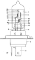
- the figure shows a side view of an incandescent lamp according to the preferred embodiment the invention.
- This lamp is a halogen lamp, in particular an H4 lamp that is used in the headlight of a Motor vehicle is provided.
- This incandescent lamp has a glass lamp vessel 1, which is in a metallic Socket 2 is fixed.
- a first incandescent filament 3 is provided within the lamp vessel 1 Generation of the low beam and a second filament 4 for generating the High beam and a dimming cap 5 are arranged.
- the two filaments 3, 4 consist of tungsten and the anti-dazzle device 5 consists of a molybdenum sheet.
- the ends 31, 32 and 41, 42 of the filaments 3, 4 are each made of a film 61, 62, 63, 64 wrapped, which consists essentially of tantalum.
- the tantalum portion in the Films 61, 62, 63, 64 is more than 99 percent by weight.
- the tantalum foils 61, 62, 63, 64 have a thickness of 0.12 mm and are each a tubular casing shaped, which surrounds the respective end 31, 32, 41 and 42 with a clamp fit.
- to Bracket and electrical power supply of the filaments 3, 4 serve three Power supply wires 7, 8, 9, which are made of molybdenum.
- the power supply wires 7, 8, 9 are fixed in a web 10 made of quartz glass, from the sealed End 11 of the lamp vessel 1 led out and each with an electric Contact 20, 21 of the base 2 connected.
- the first end 31 of the first filament 3 wrapped by the tantalum foil 61 is included the first power supply wire 7 by resistance welding between the tantalum foil 61 and the first power supply wire 7. That from the Tantalum foil 62 covered second end 32 of the first filament 3 is on the anti-dazzle device 5 by resistance welding between the tantalum foil 62 and one hump 50 arranged in the molybdenum sheet of the anti-dazzle device 5 is fixed.
- the Dimming cap 5 is used here together with the first 7 and third power supply wire 9 additionally also as a power supply for the first filament 3.
- the second filament 4 is fixed to the power supply wires 8, 9.
- the first end 41 of the second incandescent filament 4 enveloped by the tantalum foil 63 is by resistance welding between the tantalum foil 63 and the third Power supply wire 9 attached to the power supply wire 9.
- That from the tantalum foil 64 encased second end 42 of the second filament 4 is by resistance welding between the tantalum foil 64 and the second power supply wire 8 attached to the power supply wire 8.
- the molybdenum the power supply wires 7, 8, 9 or the anti-dazzle cap 5 melted and that respective filament ends of the molybdenum melt encased by the tantalum foil wetted. After the molybdenum melt has solidified, it is from the tantalum foil coated filament end fixed to the corresponding power supply.
- laser welding can also be used be performed.
- foils can also be used, for example are used, which are made of a tantalum alloy, for example a tantalum-molybdenum alloy, consist.
Landscapes
- Non-Portable Lighting Devices Or Systems Thereof (AREA)
- Resistance Heating (AREA)
Abstract
Description
Claims (5)
- Elektrische Glühlampe mit mindestens einer Glühwendel (4) und Stromzuführungen (8, 9) für die mindestens eine Glühwendel (4), wobei mindestens ein Ende (41) der mindestens einen Glühwendel (4) von einer metallischen Hülle (63) umschlossen ist, und die metallische Hülle (63) mit einer Stromzuführung (9) verschweißt ist,
dadurch gekennzeichnet, dass
die metallische Hülle (63) im wesentlichen aus Tantal oder einer Tantallegierung besteht. - Elektrische Glühlampe nach Anspruch 1, dadurch gekennzeichnet, dass die Hülle (63) aus einem Band oder einer Folie besteht, das bzw. die das mindestens eine Ende (41) der mindestens einen Glühwendel (4) umschließt.
- Elektrische Glühlampe nach Anspruch 1, dadurch gekennzeichnet, dass die Hülle (63) als Rohr ausgebildet ist, das mit Klemmsitz auf dem mindestens einem Ende (41) der mindestens einen Glühwendel (4) angeordnet ist.
- Elektrische Glühlampe nach einem der Ansprüche 1, 2 oder 3, dadurch gekennzeichnet, dass beide Enden (63, 64) der mindestens einen Glühwendel (4) jeweils von einer metallischen Hülle (63, 64) umschlossen sind, wobei die metallischen Hüllen (63, 64) jeweils mit einer Stromzuführung (8, 9) verschweißt sind.
- Elektrische Glühlampe nach Anspruch 1, dadurch gekennzeichnet, dass die Glühlampe eine Halogenglühlampe ist.
Applications Claiming Priority (2)
| Application Number | Priority Date | Filing Date | Title |
|---|---|---|---|
| DE10213297 | 2002-03-25 | ||
| DE2002113297 DE10213297A1 (de) | 2002-03-25 | 2002-03-25 | Elektrische Glühlampe |
Publications (2)
| Publication Number | Publication Date |
|---|---|
| EP1349198A2 true EP1349198A2 (de) | 2003-10-01 |
| EP1349198A3 EP1349198A3 (de) | 2006-04-19 |
Family
ID=27798173
Family Applications (1)
| Application Number | Title | Priority Date | Filing Date |
|---|---|---|---|
| EP03005640A Withdrawn EP1349198A3 (de) | 2002-03-25 | 2003-03-12 | Elektrische Glühlampe |
Country Status (2)
| Country | Link |
|---|---|
| EP (1) | EP1349198A3 (de) |
| DE (1) | DE10213297A1 (de) |
Cited By (1)
| Publication number | Priority date | Publication date | Assignee | Title |
|---|---|---|---|---|
| WO2006066534A3 (de) * | 2004-12-22 | 2006-10-19 | Patent Treuhand Ges Fuer Elektrische Gluehlampen Mbh | Befestigungsverfahren und danach hergestellte lampe |
Family Cites Families (4)
| Publication number | Priority date | Publication date | Assignee | Title |
|---|---|---|---|---|
| US4032809A (en) * | 1966-03-21 | 1977-06-28 | Westinghouse Electric Corporation | Tantalum carbide or tantalum-alloy carbide filament mounting and method |
| US4295185A (en) * | 1979-09-26 | 1981-10-13 | Westinghouse Electric Corp. | Filament mount assembly for miniature incandescent lamp, and method of manufacture |
| DE19707245A1 (de) * | 1997-02-25 | 1998-08-27 | Patent Treuhand Ges Fuer Elektrische Gluehlampen Mbh | Verfahren zur Herstellung einer elektrischen Glühlampe |
| US6281630B1 (en) * | 1997-04-28 | 2001-08-28 | Osram Sylvania, Inc. | Vehicle lamps with glare control |
-
2002
- 2002-03-25 DE DE2002113297 patent/DE10213297A1/de not_active Withdrawn
-
2003
- 2003-03-12 EP EP03005640A patent/EP1349198A3/de not_active Withdrawn
Cited By (1)
| Publication number | Priority date | Publication date | Assignee | Title |
|---|---|---|---|---|
| WO2006066534A3 (de) * | 2004-12-22 | 2006-10-19 | Patent Treuhand Ges Fuer Elektrische Gluehlampen Mbh | Befestigungsverfahren und danach hergestellte lampe |
Also Published As
| Publication number | Publication date |
|---|---|
| DE10213297A1 (de) | 2003-10-16 |
| EP1349198A3 (de) | 2006-04-19 |
Similar Documents
| Publication | Publication Date | Title |
|---|---|---|
| DE19812298C2 (de) | Verfahren zur Herstellung einer Metall-Halogenlampe sowie eine derartige Metall-Halogenlampe | |
| EP0910867B1 (de) | Verfahren zur herstellung einer elektrischen glühlampe | |
| DE19855412A1 (de) | Elektrische Lampe | |
| EP1294013B1 (de) | Glühlampe für Kraftfahrzeugscheinwerfer | |
| EP2087506B1 (de) | Halogenglühlampe | |
| EP0776025B1 (de) | Elektrische Glühlampe mit Abblendkappe und Verfahren zur Herstellung einer derartigen Lampe sowie Abblendkappe für eine elektrische Glühlampe | |
| DE10213297A1 (de) | Elektrische Glühlampe | |
| EP0321867B1 (de) | Hochdruckentladungslampe | |
| DE10336087A1 (de) | Elektrodensystem mit neuartiger Verbindung, zugehörige Lampe mit dieser Folie und Verfahren zur Herstellung der Verbindung | |
| DE69110097T2 (de) | Elektrische Glühlampe. | |
| DE69603007T2 (de) | Elektrische glühlampe | |
| DE3035786A1 (de) | Gluehlampe | |
| EP0807316B1 (de) | Verfahren zur herstellung einer elektrischen glühlampe | |
| DE19538497C2 (de) | Verfahren zur Herstellung einer elektrischen Lampe | |
| EP0588201A2 (de) | Hochdruckentladungslampe und Herstellungsverfahren für eine Hochdruckentladungslampe | |
| EP1447837A2 (de) | Glühlampe für Fahrzeugscheinwerfer | |
| EP1564789B1 (de) | Elektrische Glühlampe | |
| WO2008055943A2 (de) | Halogenglühlampe | |
| EP1560258A2 (de) | Glühlampe für Fahrzeugscheinwerfer | |
| DE102007059340B4 (de) | Stromzuführungssystem | |
| EP2106615A2 (de) | Abblendkappe mit wendel | |
| EP0914674A1 (de) | Elektrische lampe | |
| DE202006002886U1 (de) | Lampe | |
| DE3141330A1 (de) | "wolfram-gluehfaden/anschlussdraht-hartloetverbindung" | |
| DE1927796C3 (de) | Leitungsführung für elektrische Lampen und Verfahren zu ihrer Herstellung |
Legal Events
| Date | Code | Title | Description |
|---|---|---|---|
| PUAI | Public reference made under article 153(3) epc to a published international application that has entered the european phase |
Free format text: ORIGINAL CODE: 0009012 |
|
| AK | Designated contracting states |
Kind code of ref document: A2 Designated state(s): AT BE BG CH CY CZ DE DK EE ES FI FR GB GR HU IE IT LI LU MC NL PT SE SI SK TR |
|
| AX | Request for extension of the european patent |
Extension state: AL LT LV MK RO |
|
| PUAL | Search report despatched |
Free format text: ORIGINAL CODE: 0009013 |
|
| AK | Designated contracting states |
Kind code of ref document: A3 Designated state(s): AT BE BG CH CY CZ DE DK EE ES FI FR GB GR HU IE IT LI LU MC NL PT SE SI SK TR |
|
| AX | Request for extension of the european patent |
Extension state: AL LT LV MK RO |
|
| 17P | Request for examination filed |
Effective date: 20060508 |
|
| AKX | Designation fees paid |
Designated state(s): AT BE BG CH CY CZ DE DK EE ES FI FR GB GR HU IE IT LI LU MC NL PT SE SI SK TR |
|
| 17Q | First examination report despatched |
Effective date: 20070508 |
|
| STAA | Information on the status of an ep patent application or granted ep patent |
Free format text: STATUS: THE APPLICATION IS DEEMED TO BE WITHDRAWN |
|
| 18D | Application deemed to be withdrawn |
Effective date: 20071120 |