EP1348784A1 - Fettpatrone für eine Spurlagerung von Offenend-Spinnrotoren - Google Patents
Fettpatrone für eine Spurlagerung von Offenend-Spinnrotoren Download PDFInfo
- Publication number
- EP1348784A1 EP1348784A1 EP03001493A EP03001493A EP1348784A1 EP 1348784 A1 EP1348784 A1 EP 1348784A1 EP 03001493 A EP03001493 A EP 03001493A EP 03001493 A EP03001493 A EP 03001493A EP 1348784 A1 EP1348784 A1 EP 1348784A1
- Authority
- EP
- European Patent Office
- Prior art keywords
- housing
- grease
- wall
- cartridge according
- bore
- Prior art date
- Legal status (The legal status is an assumption and is not a legal conclusion. Google has not performed a legal analysis and makes no representation as to the accuracy of the status listed.)
- Withdrawn
Links
Images
Classifications
-
- F—MECHANICAL ENGINEERING; LIGHTING; HEATING; WEAPONS; BLASTING
- F16—ENGINEERING ELEMENTS AND UNITS; GENERAL MEASURES FOR PRODUCING AND MAINTAINING EFFECTIVE FUNCTIONING OF MACHINES OR INSTALLATIONS; THERMAL INSULATION IN GENERAL
- F16C—SHAFTS; FLEXIBLE SHAFTS; ELEMENTS OR CRANKSHAFT MECHANISMS; ROTARY BODIES OTHER THAN GEARING ELEMENTS; BEARINGS
- F16C33/00—Parts of bearings; Special methods for making bearings or parts thereof
- F16C33/02—Parts of sliding-contact bearings
- F16C33/04—Brasses; Bushes; Linings
- F16C33/06—Sliding surface mainly made of metal
- F16C33/10—Construction relative to lubrication
- F16C33/102—Construction relative to lubrication with grease as lubricant
-
- D—TEXTILES; PAPER
- D01—NATURAL OR MAN-MADE THREADS OR FIBRES; SPINNING
- D01H—SPINNING OR TWISTING
- D01H4/00—Open-end spinning machines or arrangements for imparting twist to independently moving fibres separated from slivers; Piecing arrangements therefor; Covering endless core threads with fibres by open-end spinning techniques
- D01H4/04—Open-end spinning machines or arrangements for imparting twist to independently moving fibres separated from slivers; Piecing arrangements therefor; Covering endless core threads with fibres by open-end spinning techniques imparting twist by contact of fibres with a running surface
- D01H4/08—Rotor spinning, i.e. the running surface being provided by a rotor
- D01H4/12—Rotor bearings; Arrangements for driving or stopping
-
- F—MECHANICAL ENGINEERING; LIGHTING; HEATING; WEAPONS; BLASTING
- F16—ENGINEERING ELEMENTS AND UNITS; GENERAL MEASURES FOR PRODUCING AND MAINTAINING EFFECTIVE FUNCTIONING OF MACHINES OR INSTALLATIONS; THERMAL INSULATION IN GENERAL
- F16C—SHAFTS; FLEXIBLE SHAFTS; ELEMENTS OR CRANKSHAFT MECHANISMS; ROTARY BODIES OTHER THAN GEARING ELEMENTS; BEARINGS
- F16C17/00—Sliding-contact bearings for exclusively rotary movement
- F16C17/04—Sliding-contact bearings for exclusively rotary movement for axial load only
- F16C17/08—Sliding-contact bearings for exclusively rotary movement for axial load only for supporting the end face of a shaft or other member, e.g. footstep bearings
-
- F—MECHANICAL ENGINEERING; LIGHTING; HEATING; WEAPONS; BLASTING
- F16—ENGINEERING ELEMENTS AND UNITS; GENERAL MEASURES FOR PRODUCING AND MAINTAINING EFFECTIVE FUNCTIONING OF MACHINES OR INSTALLATIONS; THERMAL INSULATION IN GENERAL
- F16C—SHAFTS; FLEXIBLE SHAFTS; ELEMENTS OR CRANKSHAFT MECHANISMS; ROTARY BODIES OTHER THAN GEARING ELEMENTS; BEARINGS
- F16C2340/00—Apparatus for treating textiles
- F16C2340/18—Apparatus for spinning or twisting
Definitions
- the invention relates to a grease cartridge for a track bearing of open-end spinning rotors, with one essentially cylindrical housing which contains a grease chamber containing grease has, with a track bearing ball arranged in the grease chamber, with one the grease chamber limiting rear housing wall, which has a through hole for an abutment, with a front housing wall, which has a first bore for a rotor shaft, and with a Partition wall, which has a second bore opening into the grease chamber for a rotor shaft having.
- a grease cartridge of this type is state of the art through DE 198 17 911 A1.
- the well-known Grease cartridge is designed together with the thrust bearing ball as a disposable part, whereby after Consumption of the grease the grease cartridge against a new grease cartridge with a new grease is exchanged. As a result, the workload and thus the costs for the Relubrication of the track bearing significantly reduced.
- Such grease cartridges are on one Fixed mounting of an open-end spinning unit releasably attached, for example by means of Clip connections or plug connections or the like.
- the invention is based on the object, a fat cartridge of the type mentioned design that also a relatively simple retrofitting of older open-end spinning machines Fat cartridges is possible.
- the object is achieved in that the housing in the area of the intermediate wall front housing wall having a first partial housing and a rear housing wall having the second sub-housing is divided.
- the housing of the grease cartridge is made into two that can be joined together Sub-housing divided, each of a significantly shorter length than the fully assembled housing exhibit. This gives the advantage of not including the entire housing of the grease cartridge to have to retrofit, but first the rear housing wall having to retrofit the second partial housing and then the front housing wall having the first partial housing to add. It has been shown that this clearly cost-effective retrofitting of older open-end spinning machines with grease cartridges is possible because not an assembly room that was originally not available was created by reworking must become.
- the length of the first sub-housing should be at least a third of the length of the second Partial housing. It is expediently provided that the first partial housing and second sub-housing associated with each other and used for assembly Circumferential surfaces are provided. As a result, the first partial housing can be simply Attach it to the pre-assembled second sub-housing during installation.
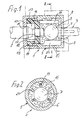
- the fat cartridge 1 shown in Figures 1 and 2 is for a track bearing of open-end spinning rotors provided, a large number of which are present in an open-end spinning machine is.
- the grease cartridge 1 contains an essentially cylindrical housing 5 which contains a grease containing fat chamber 6.
- a track bearing ball 7 is arranged in the grease chamber 6 is inherently part of the grease cartridge 1 and which is in operation when the rotor shaft 2 supports, while the thrust bearing ball 7 in turn on the bolt-like slotted Abutment 3 supports.
- the housing 5 has a rear end housing wall 8, which with a Through hole 9 is provided for the bolt-like abutment 3.
- a front housing wall 10 is provided which has a first bore 11 for has the rotor shaft 2.
- the front one closes Housing wall 10 does not directly on the fat chamber 6, but it is the fat chamber 6 delimiting partition 12 is provided which has a second bore 13 for the rotor shaft 2 having.
- the diameter of the through the first Bore 11 and the second bore 13 inserted through the rotor shaft 2 are on the Adjusted the diameter of the first bore 11 and the second bore 13 in such a way that there is a non-contact sealing of the fat chamber 6 to the outside.
- the fat cartridge 1 is designed as a disposable part, which together with the Track bearing ball 7 can be replaced when the grease is used up.
- the fat cartridge 1 is thus an overall interchangeable spare part, which is easily detachably attached to the holder 4 is.
- a such a grease cartridge 1 supplied as a spare part initially contains two in a manner not shown simple end covers for the first bore 11 and for the through bore 9, wherein these covers are then removed when mounting the grease cartridge 1 on the holder 4, when the rotor shaft 2 and the abutment 3 are inserted up to the grease chamber 6.
- the object is achieved in that the housing 5 approximately in the region of the intermediate wall 12 in a first partial housing 14 having the front housing wall 10 and one the rear one Housing wall 8 having second sub-housing 15 is divided.
- the arrangement is like this met that the length of the first partial housing 14 at least a third of the length of the second partial housing 15.
- the first partial housing 14 and the second partial housing 15 are expediently in each case with one another associated and the mounting peripheral surfaces 16 provided.
- One circumferential surface 16 is on the first part of the housing 14 inside, the other peripheral surface 16 on the second part of the housing 15 attached outside, so that the two sub-housings 14 and 15 are simple in their longitudinal direction can be joined together. This is expedient on the peripheral surfaces 16 for a press fit.
- the front housing wall 10 does not directly limit the fat chamber 6. Rather, there is such a between the fat chamber 6 and the front housing wall 10 mentioned collection space 17 for grease components emerging from the grease chamber 6.
- the Invention as was also the case with the prior art mentioned above, means provided that the grease located in the grease chamber 6 by an operator in "stir" at certain time intervals, thereby removing used grease from the old location removed and fresh grease is brought up to the bearing ball 7.
- the intermediate wall 12 is thus on a separate housing part 18 attached, which is opposite the first partial housing 14 and the second partial housing 15 is rotatably arranged.
- the one containing the partition 12 is expedient Housing part 18 rotatably supported in the first partial housing 14. It is also provided that the housing part 18 containing the intermediate wall 12 also protruding into the fat chamber 6 Stirrer blades 19 is provided, which surround the bearing ball 7 finger-like at a distance.
- the axis of the impeller 19 is coaxial with the axis of the rotor shaft 2. Through occasional rotation of the impeller 19, which after removing the rotor shaft 2 by a Operator can be made using a tool, the grease can escape, and it is thereby unused grease to the critical support point of the Rotor shaft 2 pressed against the bearing ball 7.
- the stirring vanes 19 have stop ribs 20 arranged in a stationary manner are assigned, for example radially from the hollow cylindrical peripheral wall of the second Part of the housing 15 can protrude inwards. Between these stop ribs 20, the Agitator blades 19 can be rotated, and when they abut against a stop rib 20 means this for the operator that the next time they lubricate the impeller 19 in the has to twist in another direction. You always turn the impeller 19 in the direction that is currently possible.
- the stop ribs 20, for example three or four in number, can also be the ball bearing ball 7 surrounded at a short distance, so that when removing the rotor shaft 2 as a support of the Track bearing ball 7 can serve.
Landscapes
- Engineering & Computer Science (AREA)
- General Engineering & Computer Science (AREA)
- Mechanical Engineering (AREA)
- Textile Engineering (AREA)
- Rolling Contact Bearings (AREA)
- Spinning Or Twisting Of Yarns (AREA)
Abstract
Description
Claims (8)
- Fettpatrone für eine Spurlagerung von Offenend-Spinnrotoren, mit einem im Wesentlichen zylindrischen Gehäuse, welches eine Schmierfett enthaltende Fettkammer aufweist, mit einer in der Fettkammer angeordneten Spurlagerkugel, mit einer die Fettkammer begrenzenden hinteren Gehäusewand, die eine Durchtrittsbohrung für ein Widerlager aufweist, mit einer vorderen Gehäusewand, die eine erste Bohrung für einen Rotorschaft aufweist, und mit einer Zwischenwand, die eine zweite, in die Fettkammer mündende Bohrung für einen Rotorschaft aufweist, dadurch gekennzeichnet, dass das Gehäuse (5) etwa im Bereich der Zwischenwand (12) in ein die vordere Gehäusewand (10) aufweisendes erstes Teilgehäuse (14) und ein die hintere Gehäusewand (8) aufweisendes zweites Teilgehäuse (15) unterteilt ist.
- Fettpatrone nach Anspruch 1, dadurch gekennzeichnet, dass die Zwischenwand (12) an einem Gehäuseteil (18) angebracht ist, welches gegenüber dem ersten Teilgehäuse (14) und dem zweiten Teilgehäuse (15) verdrehbar angeordnet ist.
- Fettpatrone nach Anspruch 2, dadurch gekennzeichnet, dass das die zweite Zwischenwand (12) enthaltende Gehäuseteil (18) im ersten Teilgehäuse (14) verdrehbar gelagert ist.
- Fettpatrone nach Anspruch 2 oder 3, dadurch gekennzeichnet, dass das die Zwischenwand (12) enthaltende Gehäuseteil (18) mit in die Fettkammer (6) hineinragenden Rührflügeln (19) versehen ist, welche die Spurlagerkugel (7) mit Abstand fingerartig umgeben.
- Fettpatrone nach einem der Ansprüche 1 bis 4, dadurch gekennzeichnet, dass die an der Zwischenwand (12) vorgesehene zweite Bohrung (13) einen gegenüber der in der vorderen Gehäusewand (10) vorgesehenen ersten Bohrung (11) verringerten Durchmesser aufweist.
- Fettpatrone nach einem der Ansprüche 1 bis 5, dadurch gekennzeichnet, dass zwischen der vorderen Gehäusewand (10) und der Zwischenwand (12) ein Auffangraum (17) für aus der Fettkammer (6) austretende Schmierfettbestandteile vorgesehen ist.
- Fettpatrone nach einem der Ansprüche 1 bis 6, dadurch gekennzeichnet, dass die Länge des ersten Teilgehäuses (14) wenigstens ein Drittel der Länge des zweiten Teilgehäuses (15) beträgt.
- Fettpatrone nach einem der Ansprüche 1 bis 7, dadurch gekennzeichnet, dass das erste Teilgehäuse (14) und das zweite Teilgehäuse (15) jeweils mit einander zugeordneten und der Montage dienenden Umfangsflächen (16) versehen sind.
Applications Claiming Priority (2)
| Application Number | Priority Date | Filing Date | Title |
|---|---|---|---|
| DE10214488 | 2002-03-25 | ||
| DE10214488A DE10214488A1 (de) | 2002-03-25 | 2002-03-25 | Fettpatrone für eine Spurlagerung von Offenend-Spinnrotoren |
Publications (1)
| Publication Number | Publication Date |
|---|---|
| EP1348784A1 true EP1348784A1 (de) | 2003-10-01 |
Family
ID=27798272
Family Applications (1)
| Application Number | Title | Priority Date | Filing Date |
|---|---|---|---|
| EP03001493A Withdrawn EP1348784A1 (de) | 2002-03-25 | 2003-01-23 | Fettpatrone für eine Spurlagerung von Offenend-Spinnrotoren |
Country Status (4)
| Country | Link |
|---|---|
| US (1) | US20030179970A1 (de) |
| EP (1) | EP1348784A1 (de) |
| CN (1) | CN1446958A (de) |
| DE (1) | DE10214488A1 (de) |
Families Citing this family (4)
| Publication number | Priority date | Publication date | Assignee | Title |
|---|---|---|---|---|
| DE102006031943A1 (de) * | 2006-07-11 | 2008-01-17 | Schaeffler Kg | Axialwälzlager |
| WO2015000509A1 (en) * | 2013-07-03 | 2015-01-08 | Aktiebolaget Skf | Bearing assembly with lubrication cartridge |
| CN105155055B (zh) * | 2015-10-15 | 2017-11-24 | 郑州润成轴承技术有限公司 | 转杯纺纱机的纺杯轴承机构及润滑系统 |
| CN109723821A (zh) * | 2018-12-12 | 2019-05-07 | 大连橡胶塑料机械有限公司 | 大型水下切粒机刀轴机械密封 |
Citations (3)
| Publication number | Priority date | Publication date | Assignee | Title |
|---|---|---|---|---|
| US4618273A (en) * | 1984-11-09 | 1986-10-21 | Fritz Stahlecker | Step bearing for a spinning rotor shaft |
| DE3622523A1 (de) * | 1986-07-04 | 1988-01-07 | Fritz Stahlecker | Oe-rotorspinnvorrichtung |
| DE19817911A1 (de) * | 1998-04-22 | 1999-10-28 | Novibra Gmbh | Spurlagergehäuse für einen Offenend-Spinnrotor |
Family Cites Families (4)
| Publication number | Priority date | Publication date | Assignee | Title |
|---|---|---|---|---|
| DE2514734C2 (de) * | 1975-04-04 | 1982-10-28 | Stahlecker, Fritz, 7347 Bad Überkingen | Lagerung für einen Offenend-Spinnrotor |
| DE3734545A1 (de) * | 1987-10-13 | 1989-05-03 | Schubert & Salzer Maschinen | Offenend-rotorspinnmaschine |
| DE19652507B4 (de) * | 1996-12-17 | 2009-03-12 | Maschinenfabrik Rieter Ag | Spurlager für einen mit einer Axialkraft belasteten Schaft eines Spinnrotors |
| DE19743744A1 (de) * | 1997-10-02 | 1999-04-08 | Schlafhorst & Co W | Schaft zur Lagerung und zum Antrieb eines Offenend-Spinnrotors |
-
2002
- 2002-03-25 DE DE10214488A patent/DE10214488A1/de not_active Withdrawn
-
2003
- 2003-01-23 EP EP03001493A patent/EP1348784A1/de not_active Withdrawn
- 2003-03-24 US US10/394,211 patent/US20030179970A1/en not_active Abandoned
- 2003-03-25 CN CN03107951A patent/CN1446958A/zh active Pending
Patent Citations (3)
| Publication number | Priority date | Publication date | Assignee | Title |
|---|---|---|---|---|
| US4618273A (en) * | 1984-11-09 | 1986-10-21 | Fritz Stahlecker | Step bearing for a spinning rotor shaft |
| DE3622523A1 (de) * | 1986-07-04 | 1988-01-07 | Fritz Stahlecker | Oe-rotorspinnvorrichtung |
| DE19817911A1 (de) * | 1998-04-22 | 1999-10-28 | Novibra Gmbh | Spurlagergehäuse für einen Offenend-Spinnrotor |
Also Published As
| Publication number | Publication date |
|---|---|
| US20030179970A1 (en) | 2003-09-25 |
| CN1446958A (zh) | 2003-10-08 |
| DE10214488A1 (de) | 2003-10-16 |
Similar Documents
| Publication | Publication Date | Title |
|---|---|---|
| DE69521023T2 (de) | Achslager | |
| DE3244893C2 (de) | Axialschublager fuer turbolader | |
| DE3126243C2 (de) | Nebenantrieb einer Brennkraftmaschine | |
| DE3779904T2 (de) | Lager fuer hochgeschwindigkeitsmotor. | |
| DE19817911A1 (de) | Spurlagergehäuse für einen Offenend-Spinnrotor | |
| DE2733377A1 (de) | Schmiersystem fuer eine lageranordnung in einer turbine mit treibstoffzufuhr | |
| DE10201055A1 (de) | Hydraulische Dichtungsanordnung | |
| DE102018104247A1 (de) | Zentrifugalkompressor | |
| DE3720745C2 (de) | ||
| EP3688331B1 (de) | Verfahren und vorrichtung zum schmieren eines kreuzgelenkes | |
| DE2451562A1 (de) | Lippendichtungsanordnung | |
| WO2020083434A1 (de) | Lagervorrichtung für einen abgasturbolader und abgasturbolader | |
| DE3407081C2 (de) | ||
| DE10214488A1 (de) | Fettpatrone für eine Spurlagerung von Offenend-Spinnrotoren | |
| EP1968871A1 (de) | Trommelmotor | |
| DE19652507B4 (de) | Spurlager für einen mit einer Axialkraft belasteten Schaft eines Spinnrotors | |
| DE2631376B1 (de) | Kreuzkopfzapfenlager fuer Kolbenmaschinen,insbesondere fuer Dieselbrennkraftmaschinen | |
| DE7000388U (de) | Schmiervorrichtung fuer leitlager. | |
| DE102015006311B4 (de) | Planetengetriebe mit Reservoir für Bolzenschmierung | |
| DE19651417B4 (de) | Auflöseeinrichtung für Offenend-Spinnmaschinen | |
| EP3290552A1 (de) | Galettenwalze | |
| DE3714884C2 (de) | Lagerung eines Rotationskörpers in einer Bohrmaschine | |
| DE10237040B4 (de) | Vorrichtung zum Abdichten einer Öffnung eines Rotorgehäuses | |
| DE112013005092B4 (de) | Kupplungsbeölung | |
| DE1813749A1 (de) | Motorgetriebene Pumpe mit Lagergestell und Verfahren zu ihrer Herstellung |
Legal Events
| Date | Code | Title | Description |
|---|---|---|---|
| PUAI | Public reference made under article 153(3) epc to a published international application that has entered the european phase |
Free format text: ORIGINAL CODE: 0009012 |
|
| AK | Designated contracting states |
Kind code of ref document: A1 Designated state(s): AT BE BG CH CY CZ DE DK EE ES FI FR GB GR HU IE IT LI LU MC NL PT SE SI SK TR |
|
| AX | Request for extension of the european patent |
Extension state: AL LT LV MK RO |
|
| 17P | Request for examination filed |
Effective date: 20030909 |
|
| AKX | Designation fees paid |
Designated state(s): CH CZ IT LI |
|
| REG | Reference to a national code |
Ref country code: DE Ref legal event code: 8566 |
|
| 17Q | First examination report despatched |
Effective date: 20040916 |
|
| STAA | Information on the status of an ep patent application or granted ep patent |
Free format text: STATUS: THE APPLICATION IS DEEMED TO BE WITHDRAWN |
|
| 18D | Application deemed to be withdrawn |
Effective date: 20050127 |