EP1347167A1 - Stellantrieb - Google Patents
Stellantrieb Download PDFInfo
- Publication number
- EP1347167A1 EP1347167A1 EP02027328A EP02027328A EP1347167A1 EP 1347167 A1 EP1347167 A1 EP 1347167A1 EP 02027328 A EP02027328 A EP 02027328A EP 02027328 A EP02027328 A EP 02027328A EP 1347167 A1 EP1347167 A1 EP 1347167A1
- Authority
- EP
- European Patent Office
- Prior art keywords
- unit
- drive
- housing
- output
- shaft
- Prior art date
- Legal status (The legal status is an assumption and is not a legal conclusion. Google has not performed a legal analysis and makes no representation as to the accuracy of the status listed.)
- Granted
Links
- 238000002485 combustion reaction Methods 0.000 claims abstract description 4
- 230000005405 multipole Effects 0.000 claims 1
- 230000005540 biological transmission Effects 0.000 abstract description 8
- 238000003860 storage Methods 0.000 description 6
- 238000009434 installation Methods 0.000 description 3
- 238000011109 contamination Methods 0.000 description 2
- 238000006243 chemical reaction Methods 0.000 description 1
- 238000006073 displacement reaction Methods 0.000 description 1
- 238000004519 manufacturing process Methods 0.000 description 1
- 230000001105 regulatory effect Effects 0.000 description 1
- 238000005476 soldering Methods 0.000 description 1
- 238000013519 translation Methods 0.000 description 1
- 230000014616 translation Effects 0.000 description 1
- 238000003466 welding Methods 0.000 description 1
Images


Classifications
-
- H—ELECTRICITY
- H02—GENERATION; CONVERSION OR DISTRIBUTION OF ELECTRIC POWER
- H02K—DYNAMO-ELECTRIC MACHINES
- H02K7/00—Arrangements for handling mechanical energy structurally associated with dynamo-electric machines, e.g. structural association with mechanical driving motors or auxiliary dynamo-electric machines
- H02K7/10—Structural association with clutches, brakes, gears, pulleys or mechanical starters
- H02K7/116—Structural association with clutches, brakes, gears, pulleys or mechanical starters with gears
- H02K7/1163—Structural association with clutches, brakes, gears, pulleys or mechanical starters with gears where at least two gears have non-parallel axes without having orbital motion
-
- F—MECHANICAL ENGINEERING; LIGHTING; HEATING; WEAPONS; BLASTING
- F02—COMBUSTION ENGINES; HOT-GAS OR COMBUSTION-PRODUCT ENGINE PLANTS
- F02M—SUPPLYING COMBUSTION ENGINES IN GENERAL WITH COMBUSTIBLE MIXTURES OR CONSTITUENTS THEREOF
- F02M26/00—Engine-pertinent apparatus for adding exhaust gases to combustion-air, main fuel or fuel-air mixture, e.g. by exhaust gas recirculation [EGR] systems
- F02M26/52—Systems for actuating EGR valves
- F02M26/53—Systems for actuating EGR valves using electric actuators, e.g. solenoids
- F02M26/54—Rotary actuators, e.g. step motors
-
- F—MECHANICAL ENGINEERING; LIGHTING; HEATING; WEAPONS; BLASTING
- F16—ENGINEERING ELEMENTS AND UNITS; GENERAL MEASURES FOR PRODUCING AND MAINTAINING EFFECTIVE FUNCTIONING OF MACHINES OR INSTALLATIONS; THERMAL INSULATION IN GENERAL
- F16H—GEARING
- F16H1/00—Toothed gearings for conveying rotary motion
- F16H1/02—Toothed gearings for conveying rotary motion without gears having orbital motion
- F16H1/04—Toothed gearings for conveying rotary motion without gears having orbital motion involving only two intermeshing members
- F16H1/12—Toothed gearings for conveying rotary motion without gears having orbital motion involving only two intermeshing members with non-parallel axes
- F16H1/14—Toothed gearings for conveying rotary motion without gears having orbital motion involving only two intermeshing members with non-parallel axes comprising conical gears only
-
- F—MECHANICAL ENGINEERING; LIGHTING; HEATING; WEAPONS; BLASTING
- F16—ENGINEERING ELEMENTS AND UNITS; GENERAL MEASURES FOR PRODUCING AND MAINTAINING EFFECTIVE FUNCTIONING OF MACHINES OR INSTALLATIONS; THERMAL INSULATION IN GENERAL
- F16H—GEARING
- F16H1/00—Toothed gearings for conveying rotary motion
- F16H1/02—Toothed gearings for conveying rotary motion without gears having orbital motion
- F16H1/04—Toothed gearings for conveying rotary motion without gears having orbital motion involving only two intermeshing members
- F16H1/12—Toothed gearings for conveying rotary motion without gears having orbital motion involving only two intermeshing members with non-parallel axes
- F16H1/16—Toothed gearings for conveying rotary motion without gears having orbital motion involving only two intermeshing members with non-parallel axes comprising worm and worm-wheel
-
- F—MECHANICAL ENGINEERING; LIGHTING; HEATING; WEAPONS; BLASTING
- F16—ENGINEERING ELEMENTS AND UNITS; GENERAL MEASURES FOR PRODUCING AND MAINTAINING EFFECTIVE FUNCTIONING OF MACHINES OR INSTALLATIONS; THERMAL INSULATION IN GENERAL
- F16H—GEARING
- F16H37/00—Combinations of mechanical gearings, not provided for in groups F16H1/00 - F16H35/00
- F16H37/02—Combinations of mechanical gearings, not provided for in groups F16H1/00 - F16H35/00 comprising essentially only toothed or friction gearings
- F16H37/04—Combinations of toothed gearings only
- F16H37/041—Combinations of toothed gearings only for conveying rotary motion with constant gear ratio
-
- H—ELECTRICITY
- H02—GENERATION; CONVERSION OR DISTRIBUTION OF ELECTRIC POWER
- H02K—DYNAMO-ELECTRIC MACHINES
- H02K11/00—Structural association of dynamo-electric machines with electric components or with devices for shielding, monitoring or protection
-
- H—ELECTRICITY
- H02—GENERATION; CONVERSION OR DISTRIBUTION OF ELECTRIC POWER
- H02K—DYNAMO-ELECTRIC MACHINES
- H02K5/00—Casings; Enclosures; Supports
- H02K5/04—Casings or enclosures characterised by the shape, form or construction thereof
- H02K5/22—Auxiliary parts of casings not covered by groups H02K5/06-H02K5/20, e.g. shaped to form connection boxes or terminal boxes
- H02K5/225—Terminal boxes or connection arrangements
Definitions
- the invention relates to an actuating device for valve and flap devices Internal combustion engine with a drive unit consisting of one in a first Housing arranged drive, in particular an electric motor with a drive shaft exists and one in a second housing, which with the first is connected, arranged output unit, which consists of a with the drive shaft of the Drive connected transmission unit and an integrated in the second housing Storage unit exists.
- the invention is based on the object of a universally applicable control element to create, which both with changed space conditions as well different actuating forces required can be used.
- valve or flap means can be operated via the radial or the axial output shaft.
- one of the output shafts can therefore optionally be used for driving can be used by valve or flap devices.
- Output unit of this actuator from a fixed on the motor drive shaft Bevel or worm gear, which is a second larger bevel or Drives worm wheel, but its diameter is not larger than that Housing of the driving motor.
- This second worm wheel is firmly connected with a shaft, which is mounted in a bearing unit integrated in the housing and on which has a second smaller worm gear or helical gear, which drives the two larger helical spur gears, which with the two output shafts are connected, which in turn are mounted in the bearing unit are.
- This type of self-locking gearbox is extremely compact, so that the diameter of the housing of the output unit is not larger than that the drive unit. Only the connection flange and connector socket protrude the diameter of the drive unit. Depending on the available space, it is however also conceivable to arrange the connector socket in alignment with the motor housing.
- the output unit and the transmission are further designed so that different motor sizes and thus motor powers can be selected, depending on which components are to be driven and which actuating forces for them are needed. It is integrated into the housing, just like the conventional one electric drive module, an electronic unit for control and sensor technology of the Drive that is controlled via a multi-pin standard plug. As a sensor usually a non-contact, in particular a Hall sensor is used here.
- the axial shifted parallel to the drive shaft due to the gear arrangement The output shaft as well as the radial output shaft lead through two corresponding ones Through openings in the housing to the components to be driven.
- the through openings each have pre-assembled seals, so that no contamination can penetrate into the housing.
- FIG. 1 shows the side view of such an adjustment device with a drive unit, Gear unit, output shafts and the associated housing.
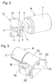
- Figure 2 shows an actuating device according to the invention without a housing in perspective Presentation.
- Figure 3 shows the embodiment of the invention in perspective with housing and electrical connection.
- FIG. 4 shows the embodiment according to the invention without the housing of the output unit but with the storage unit in perspective
- the drive unit A of the actuating device shown for valve and flap devices consists of an electric motor 1 with a drive shaft 2 and Housing 3.
- a first worm wheel 4 which is designed as a bevel gear and rotatably connected to the drive shaft 2 and is axially secured against displacement.
- This bevel gear 4 drives via its teeth a second worm gear 5, which is also designed as a bevel gear.
- This bevel gear is rotatably connected to a shaft 6.
- the center line of this wave 6 intersects the center line of the drive shaft 2 at an angle of 90 °.
- On the wave 6 is non-rotatably connected to it a helical small spur gear 7, which in two further helical gears of the radial output 8 and the axial output 9 engages.
- the first spur gear 8 is thus on the radial Output shaft 10, the second spur gear 9 on the axial output shaft 11.
- the housing 12 has a first through opening 13 for the radial output shaft 10 and a second through opening 14 through which the axial output shaft at Assembly of the output unit B occurs. Both through openings 13, 14 have pre-assembled Seals 15 and 16 on the transmission from external contamination Protect when installed.
- the center line of the shaft 10 intersects the Center line of the input shaft at an angle of 90 °, while the center line of the output shaft 11 is offset parallel to the center line of the drive shaft 2.
- An electronic unit 18 indicated in FIG. 4 for control is also integrated and sensors, which in the exemplary embodiment have a three-pin standard plug 19 is controlled.
- This connector is part of the housing 12, which the further has an L-shaped connecting flange 20 which has four through holes has two for the connection of the adjusting device in the axial direction 21st and two for connection in the radial direction 22 to the motor housing.
- a storage unit 23 is also shown, for receiving and storage the shaft 6 and the two output shafts 10, 11 serves.
- This storage unit is executed so that the gear unit C is integrated in it and initially with one exception the radial output shaft 10 can be assembled. It includes also the control electronics 18.
- the housing 12 is about when assembling the bearing unit 23 is pushed with the gear unit C without the radial output shaft.
- the inner dimensions of the housing 12 and the outer dimensions of the bearing unit 23 are selected so that the bearing unit 23 is firmly seated after being pushed on of the housing 12 via the bearing unit 23 and no additional attachment the bearing or gear unit C in the housing is necessary. Only after that can the radial output shaft 10 with the helical gear 8 through the passage opening 13 with the pre-assembled seal 15 of the housing 12 into the transmission and thus into the bearing unit 23 against an attachment point 24 the storage unit 23 are pushed and clipped.
- this shaft 10 must be at least as large as that of the Gear 8, since there is a seal on the housing passage opening 13 must as well as the gear 8 must fit through this passage opening 13. For this reason, the shaft 10 with a shoulder 17 to the gear side.
- this embodiment requires extremely little installation space.
- the total existing diameter is not larger than that of the drive unit, so the electric motor.
- the housing of the drive unit 3 can with the Housing 12 can be connected in different ways. Both are to be presented integral connections by welding or soldering as well as plug connections with appropriate execution of connection devices on the two Housings. Flanging or the like is also conceivable.
Landscapes
- Engineering & Computer Science (AREA)
- Power Engineering (AREA)
- Chemical & Material Sciences (AREA)
- Combustion & Propulsion (AREA)
- Mechanical Engineering (AREA)
- General Engineering & Computer Science (AREA)
- Electrically Driven Valve-Operating Means (AREA)
- Mechanically-Actuated Valves (AREA)
- Gear Transmission (AREA)
- Valve Device For Special Equipments (AREA)
Abstract
Description
Claims (8)
- Stellvorrichtung für Ventil- und Klappeneinrichtungen einer Verbrennungskraftmaschine mit einer Antriebseinheit, die aus einem in einem ersten Gehäuse angeordneten Antrieb, insbesondere einem Elektromotor mit einer Antriebswelle besteht und einer in einem zweiten Gehäuse, welches mit dem ersten verbunden ist, angeordneten Abtriebseinheit, die aus einer mit der Antriebswelle des Antriebes verbundenen Getriebeeinheit und einer in das zweite Gehäuse integrierten Lagereinheit besteht, dadurch gekennzeichnet, dass die Getriebeeinheit C mindestens eine radiale Abtriebswelle (10) und eine axiale Abtriebswelle (11) aufweist, wobei die Ventil- oder Klappeneinrichtungen über die radiale oder die axiale Abtriebswelle (10,11) betätigt werden.
- Stellvorrichtung nach Anspruch 1 dadurch gekennzeichnet, dass das Gehäuse (12) der Abtriebseinheit B über zwei Verschraubungsebenen entsprechend des Anschlusses der zwei Abtriebswellen (10,11) verfügt.
- Stellvorrichtung nach Anspruch 1 oder 2 dadurch gekennzeichnet, dass die Abtriebseinheit B ein standardisiertes Modul ist, welches bezüglich Größe, Form und Stabilität so ausgelegt ist, daß Motorgröße und -leistung des Antriebes frei wählbar sind.
- Stellvorrichtung nach einem der vorhergehenden Ansprüche dadurch gekennzeichnet, dass der Außendurchmesser des Gehäuses (12), in dem die Lagereinheit (23) und die Getriebeeinheit C der Abtriebseinheit B angeordnet sind, ohne Anschlußflansch (19) und Steckverbinderdose (18) aufgrund der kompakten Bauform nicht größer ist als der Außendurchmesser eines verwendeten Motorgehäuses (3).
- Stellvorrichtung nach einem der vorhergehenden Ansprüche dadurch gekennzeichnet, dass in die Lagereinheit (23) eine Elektronikeinheit (18) zur Steuerung und Sensorik des Antriebes integriert ist, die über einen mehrpoligen Normstekker (19) ansteuerbar ist.
- Stellvorrichtung nach einem der vorhergehenden Ansprüche dadurch gekennzeichnet, dass die Sensorik einen berührungslosen Sensor, insbesondere einen Hall-Sensor aufweist.
- Stellvorrichtung nach einem der vorhergehenden Ansprüche dadurch gekennzeichnet, dass die axiale Abtriebswelle (11) parallel verschoben zur Antriebswelle (2) angeordnet ist.
- Stellvorrichtung nach einem der vorhergehenden Ansprüche dadurch gekennzeichnet, dass das Gehäuse mindestens eine Durchgangsöffnung (13) radial zur Antriebswelle (2) der Antriebseinheit und eine Durchgangsöffnung (14) axial zur Antriebswelle (2) der Antriebseinheit aufweist durch die die Abtriebswellen (10,11) der Stellvorrichtung geführt sind, um den Kontakt zum anzutreibenden Bauteil herzustellen, und dass Dichtungen (15,16) im Gehäuse (12) vormontiert sind, die im fertig montierten Zustand von innen an der Gehäusewand anliegen und um die Abtriebswellen angeordnet sind und die Durchgangsöffnungen (13,14) mit den Abtriebswellen nach aussen abdichten.
Applications Claiming Priority (2)
| Application Number | Priority Date | Filing Date | Title |
|---|---|---|---|
| DE10212189 | 2002-03-20 | ||
| DE10212189A DE10212189A1 (de) | 2002-03-20 | 2002-03-20 | Stellantrieb |
Publications (2)
| Publication Number | Publication Date |
|---|---|
| EP1347167A1 true EP1347167A1 (de) | 2003-09-24 |
| EP1347167B1 EP1347167B1 (de) | 2004-09-01 |
Family
ID=27771433
Family Applications (1)
| Application Number | Title | Priority Date | Filing Date |
|---|---|---|---|
| EP02027328A Expired - Lifetime EP1347167B1 (de) | 2002-03-20 | 2002-12-07 | Stellantrieb |
Country Status (3)
| Country | Link |
|---|---|
| EP (1) | EP1347167B1 (de) |
| DE (2) | DE10212189A1 (de) |
| ES (1) | ES2223025T3 (de) |
Families Citing this family (2)
| Publication number | Priority date | Publication date | Assignee | Title |
|---|---|---|---|---|
| DE102004040818B4 (de) * | 2004-08-24 | 2009-04-02 | Pierburg Gmbh | Abgasklappeneinrichtung |
| DE102008014609A1 (de) * | 2008-03-17 | 2009-09-24 | Continental Automotive Gmbh | Aktuator für Schaltelement einer Verbrennungskraftmaschine |
Citations (4)
| Publication number | Priority date | Publication date | Assignee | Title |
|---|---|---|---|---|
| US4873957A (en) * | 1987-02-25 | 1989-10-17 | Mitsubishi Denki Kabushiki Kaisha | Throttle valve control apparatus |
| EP0939245A1 (de) * | 1998-02-25 | 1999-09-01 | Eaton Corporation | Motorisiertes zwei stufiges Betätigungsgerät |
| EP1101919A2 (de) * | 1999-11-19 | 2001-05-23 | Eaton Corporation | Servomotor mit Schneckenantrieb und Federrückstellvorrichtung und Drehklappe versehen mit solchem Servomotor |
| US20010032632A1 (en) * | 2000-02-18 | 2001-10-25 | Cook John Edward | Rotary valve actuating system |
Family Cites Families (3)
| Publication number | Priority date | Publication date | Assignee | Title |
|---|---|---|---|---|
| DE3704188C2 (de) * | 1987-02-11 | 1995-06-14 | Pierburg Gmbh | Drosselklappenansteller für Luft- bzw. Brenngemischdrosseleinrichtungen von Brennkraftmaschinen |
| DE19502341A1 (de) * | 1995-01-26 | 1996-08-01 | Wiha Werkzeuge Willi Hahn Gmbh | Werkzeugmaschine |
| DE19709748A1 (de) * | 1996-12-16 | 1998-06-18 | Bosch Gmbh Robert | Drosselvorrichtung für eine Brennkraftmaschine |
-
2002
- 2002-03-20 DE DE10212189A patent/DE10212189A1/de not_active Withdrawn
- 2002-12-07 ES ES02027328T patent/ES2223025T3/es not_active Expired - Lifetime
- 2002-12-07 EP EP02027328A patent/EP1347167B1/de not_active Expired - Lifetime
- 2002-12-07 DE DE50200922T patent/DE50200922D1/de not_active Expired - Lifetime
Patent Citations (4)
| Publication number | Priority date | Publication date | Assignee | Title |
|---|---|---|---|---|
| US4873957A (en) * | 1987-02-25 | 1989-10-17 | Mitsubishi Denki Kabushiki Kaisha | Throttle valve control apparatus |
| EP0939245A1 (de) * | 1998-02-25 | 1999-09-01 | Eaton Corporation | Motorisiertes zwei stufiges Betätigungsgerät |
| EP1101919A2 (de) * | 1999-11-19 | 2001-05-23 | Eaton Corporation | Servomotor mit Schneckenantrieb und Federrückstellvorrichtung und Drehklappe versehen mit solchem Servomotor |
| US20010032632A1 (en) * | 2000-02-18 | 2001-10-25 | Cook John Edward | Rotary valve actuating system |
Also Published As
| Publication number | Publication date |
|---|---|
| DE10212189A1 (de) | 2003-10-16 |
| EP1347167B1 (de) | 2004-09-01 |
| ES2223025T3 (es) | 2005-02-16 |
| DE50200922D1 (de) | 2004-10-07 |
Similar Documents
| Publication | Publication Date | Title |
|---|---|---|
| WO2009156268A1 (de) | Aktuator | |
| DE60100225T2 (de) | Elektronisches Drosselklappensteuersystem mit reduzierter Reibung und reduziertem Verschleiss | |
| EP2089619A1 (de) | Regelvorrichtung für eine verbrennungskraftmaschine | |
| EP1068093A1 (de) | Spindel- oder schneckenantrieb für verstelleinrichtungen in kraftfahrzeugen | |
| EP1456561A1 (de) | Planetengetriebe, getriebemotor und baureihe von getriebemotoren | |
| DE102005011872A1 (de) | Motormodul für ein elektromechanisches Hybridgetriebe | |
| EP3717722B1 (de) | Spindelantriebsbaugruppe sowie fahrzeugklappe mit einer spindelantriebsbaugruppe | |
| DE202012009415U1 (de) | Industriegetriebe | |
| DE102017207929B4 (de) | Stelleinrichtung und zugehöriges Herstellungsverfahren | |
| EP0413082A1 (de) | Lastverstelleinrichtung | |
| EP3717725B1 (de) | Spindelantriebsbaugruppe, fahrzeugklappe mit einer spindelantriebsbaugruppe sowie verfahren zur montage einer spindelantriebsbaugruppe | |
| DE10321653B3 (de) | Stellvorrichtung für eine Verbrennungskraftmaschine | |
| DE19861273B4 (de) | Spindel- oder Schneckenantrieb für Verstelleinrichtungen in Kraftfahrzeugen | |
| DE102004003665A1 (de) | Stellvorrichtung | |
| EP1156200A2 (de) | Klappenstelleinheit | |
| EP2398698B1 (de) | Bootsantrieb mit steuereinrichtung | |
| DE102019128049B4 (de) | Elektrische Stelleinheit | |
| DE10336976B4 (de) | Ventilvorrichtung für eine Verbrennungskraftmaschine | |
| DE102018124220A1 (de) | Elektrischer Pumpenaktor und Kupplung, sowie Verfahren zur Montage eines Pumpenaktors | |
| EP1347167B1 (de) | Stellantrieb | |
| EP3913267B1 (de) | Antriebsvorrichtung zum betätigen eines drehschiebers | |
| WO2020048668A1 (de) | Elektromechanische fahrzeuglenkung | |
| DE102005027441A1 (de) | Motor mit einem Reduktionsgetriebe und einer Steuerschaltung | |
| DE102021006591A1 (de) | Expansionsventil | |
| EP2138690A1 (de) | Aktuator |
Legal Events
| Date | Code | Title | Description |
|---|---|---|---|
| PUAI | Public reference made under article 153(3) epc to a published international application that has entered the european phase |
Free format text: ORIGINAL CODE: 0009012 |
|
| 17P | Request for examination filed |
Effective date: 20021207 |
|
| AK | Designated contracting states |
Kind code of ref document: A1 Designated state(s): AT BE BG CH CY CZ DE DK EE ES FI FR GB GR IE IT LI LU MC NL PT SE SI SK TR |
|
| AX | Request for extension of the european patent |
Extension state: AL LT LV MK RO |
|
| GRAP | Despatch of communication of intention to grant a patent |
Free format text: ORIGINAL CODE: EPIDOSNIGR1 |
|
| GRAS | Grant fee paid |
Free format text: ORIGINAL CODE: EPIDOSNIGR3 |
|
| AKX | Designation fees paid |
Designated state(s): DE ES FR GB IT |
|
| GRAA | (expected) grant |
Free format text: ORIGINAL CODE: 0009210 |
|
| AK | Designated contracting states |
Kind code of ref document: B1 Designated state(s): DE ES FR GB IT |
|
| REG | Reference to a national code |
Ref country code: GB Ref legal event code: FG4D Free format text: NOT ENGLISH |
|
| GBT | Gb: translation of ep patent filed (gb section 77(6)(a)/1977) |
Effective date: 20040910 |
|
| REG | Reference to a national code |
Ref country code: IE Ref legal event code: FG4D Free format text: GERMAN |
|
| REF | Corresponds to: |
Ref document number: 50200922 Country of ref document: DE Date of ref document: 20041007 Kind code of ref document: P |
|
| REG | Reference to a national code |
Ref country code: ES Ref legal event code: FG2A Ref document number: 2223025 Country of ref document: ES Kind code of ref document: T3 |
|
| REG | Reference to a national code |
Ref country code: IE Ref legal event code: FD4D |
|
| PLBE | No opposition filed within time limit |
Free format text: ORIGINAL CODE: 0009261 |
|
| STAA | Information on the status of an ep patent application or granted ep patent |
Free format text: STATUS: NO OPPOSITION FILED WITHIN TIME LIMIT |
|
| ET | Fr: translation filed | ||
| 26N | No opposition filed |
Effective date: 20050602 |
|
| PGFP | Annual fee paid to national office [announced via postgrant information from national office to epo] |
Ref country code: ES Payment date: 20051216 Year of fee payment: 4 |
|
| GBPC | Gb: european patent ceased through non-payment of renewal fee |
Effective date: 20061207 |
|
| PG25 | Lapsed in a contracting state [announced via postgrant information from national office to epo] |
Ref country code: GB Free format text: LAPSE BECAUSE OF NON-PAYMENT OF DUE FEES Effective date: 20061207 |
|
| REG | Reference to a national code |
Ref country code: ES Ref legal event code: FD2A Effective date: 20061209 |
|
| PG25 | Lapsed in a contracting state [announced via postgrant information from national office to epo] |
Ref country code: ES Free format text: LAPSE BECAUSE OF NON-PAYMENT OF DUE FEES Effective date: 20061209 |
|
| PGFP | Annual fee paid to national office [announced via postgrant information from national office to epo] |
Ref country code: FR Payment date: 20100105 Year of fee payment: 8 Ref country code: IT Payment date: 20091223 Year of fee payment: 8 |
|
| REG | Reference to a national code |
Ref country code: FR Ref legal event code: ST Effective date: 20110831 |
|
| PG25 | Lapsed in a contracting state [announced via postgrant information from national office to epo] |
Ref country code: FR Free format text: LAPSE BECAUSE OF NON-PAYMENT OF DUE FEES Effective date: 20110103 |
|
| PG25 | Lapsed in a contracting state [announced via postgrant information from national office to epo] |
Ref country code: IT Free format text: LAPSE BECAUSE OF NON-PAYMENT OF DUE FEES Effective date: 20101207 |
|
| PGFP | Annual fee paid to national office [announced via postgrant information from national office to epo] |
Ref country code: DE Payment date: 20151217 Year of fee payment: 14 |
|
| REG | Reference to a national code |
Ref country code: DE Ref legal event code: R119 Ref document number: 50200922 Country of ref document: DE |
|
| PG25 | Lapsed in a contracting state [announced via postgrant information from national office to epo] |
Ref country code: DE Free format text: LAPSE BECAUSE OF NON-PAYMENT OF DUE FEES Effective date: 20170701 |