EP1346859A2 - Steuereinrichtung für Heizungs- und/oder Klimaanlagen - Google Patents
Steuereinrichtung für Heizungs- und/oder Klimaanlagen Download PDFInfo
- Publication number
- EP1346859A2 EP1346859A2 EP03006571A EP03006571A EP1346859A2 EP 1346859 A2 EP1346859 A2 EP 1346859A2 EP 03006571 A EP03006571 A EP 03006571A EP 03006571 A EP03006571 A EP 03006571A EP 1346859 A2 EP1346859 A2 EP 1346859A2
- Authority
- EP
- European Patent Office
- Prior art keywords
- control device
- roller
- housing
- drive shaft
- frame
- Prior art date
- Legal status (The legal status is an assumption and is not a legal conclusion. Google has not performed a legal analysis and makes no representation as to the accuracy of the status listed.)
- Granted
Links
Images
Classifications
-
- B—PERFORMING OPERATIONS; TRANSPORTING
- B60—VEHICLES IN GENERAL
- B60H—ARRANGEMENTS OF HEATING, COOLING, VENTILATING OR OTHER AIR-TREATING DEVICES SPECIALLY ADAPTED FOR PASSENGER OR GOODS SPACES OF VEHICLES
- B60H1/00—Heating, cooling or ventilating [HVAC] devices
- B60H1/00642—Control systems or circuits; Control members or indication devices for heating, cooling or ventilating devices
- B60H1/00664—Construction or arrangement of damper doors
- B60H1/00692—Damper doors moved by translation, e.g. curtain doors
-
- B—PERFORMING OPERATIONS; TRANSPORTING
- B60—VEHICLES IN GENERAL
- B60H—ARRANGEMENTS OF HEATING, COOLING, VENTILATING OR OTHER AIR-TREATING DEVICES SPECIALLY ADAPTED FOR PASSENGER OR GOODS SPACES OF VEHICLES
- B60H1/00—Heating, cooling or ventilating [HVAC] devices
- B60H1/00642—Control systems or circuits; Control members or indication devices for heating, cooling or ventilating devices
- B60H1/00664—Construction or arrangement of damper doors
- B60H2001/00728—Film doors
Definitions
- the invention relates to a control device for controlling air flows in particular in heating and / or air conditioning systems of motor vehicles in particular according to the preamble of claim 1.
- DE 44 42 000 discloses a so-called blind cassette, which in Air ducts of a heating and / or air conditioning for a motor vehicle is used, namely to control the amount and also the direction the passing air stream.
- the cassette is through a frame formed in which a plurality of pivotable blades is arranged, which form a flap blind.
- This blind cassette has a variety of Split, due to the lamella type and the associated Control. In narrow air gaps whistling can occur and possibly also rattling noises.
- a Venetian blind cassette a relatively high air resistance, d. H. Pressure drop on.
- Latter consists of a roller belt, which is partially provided with cutouts and the passage openings of air flow channels closes or partially or completely free.
- the roller belt is about individual rollers guided, wound up and unwound and by means of a servomotor over a Drive roller brought into closing, opening or intermediate position.
- roller blind A further development of such a roller blind was made by EP 0 705 725 A1 known.
- a film-like roller tape which, over his Length distributed, a variety of different cutouts for the Passage of an air flow, at the outlet openings of the Air conditioning housing passed and thus controlled the Outlet cross section for the air.
- one Roller conveyor located immediately in front of the radiator and controls the through the radiator passing through the air and the radiator flowing bypass current.
- This type of roller blinds is in each case to the special installation conditions and configurations of a special Heating and / or air conditioning adapted.
- the control device is advantageous as a structural unit with a roller blind educated. In this case, the control device starting from the middle open and close. In another embodiment may also of open and close a page.
- control unit is in the form of a cassette formed, which is versatile in an air conditioner, as they individually or in combination with other cassettes in different places Control of air flows can be used.
- the cassette is made a housing with drive and deflection shaft, via which one as endless roller blind trained roller blind is guided.
- the transport of the Rollbands via a peripheral perforation in the roll band and a Gearing on the drive shaft or direct attachment of the band by gluing, welding, clamping, on the drive shaft. This results a slip-free transport of the roller conveyor and thus an exact Adjustment of the desired flow cross-section for the air flow.
- the Housing longitudinal slotted hollow cylindrical areas, the drive and Pick up the deflection shaft The wall of the hollow cylinder ends in one elastic tongue, which applies with a radius to the roll band and thus acts as a clamping element. This allows you to work on a tensioner without.
- the housing is made of a few Assembled plastic parts, which are easily assembled by clipping and kept together. In this respect, the manufacturing costs are low.
- the drive via a flanged actuator, the by rotation of the drive shaft the desired passage cross section sets.
- the drive shaft as a hollow shaft be formed, which gives the possibility of the servomotor at least partially integrated into the drive shaft.
- the cassette with Roller blind and drive as a complete unit for installation in one Heating and / or air conditioning to be delivered.
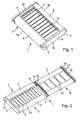
- Fig. 1 shows a unit constructed as a cassette 1 with a roller blind 2, which is designed as an endless roller belt.
- a cassette is in a not shown here heating and / or air conditioning for a Motor vehicle used, the cassette in terms of their Outside dimensions adapted to the respective air flow channel, so that the entire air flow cross section through the cassette controlled can be.
- the cassette 1 consists of a housing 3, which has an approximately rectangular floor plan with two longitudinal sides 3a, 3b and two narrow sides 3c, 3d.
- the Housing 3 each in the form of a slotted hollow cylinder 4, 5, within which a drive shaft 6 and a deflection shaft 7th are included.
- a more detailed view of the hollow cylinder 4 shows Fig. 4.
- the housing 3 is on its narrow sides 3c, 3d by side parts 8, 9 completed.
- the drive shaft 6 and the deflection shaft 7 are with not shown in front end pin or hollow pin in corresponding bearing points of the side parts 8, 9 rotatably mounted.
- On the Circumference of the drive shaft 6 and the deflection shaft 7 is the roller belt. 2 guided; It has a cutout 10 which is a rectangular Cross section between the longitudinal and narrow sides 3a, 3b, 3c, 3d releases, and by opposing movement of the band sections of the endless Rolling tape 2, see also the description of FIG. 4 and FIG.
- Fig. 2 shows the cassette 1 of FIG. 1 in a preassembled state, d. H. in two preassembled assemblies 11 and 12.
- the first assembly 11 consists of the housing 3 with the two hollow cylindrical Edge regions 4 and 5 and from the clipped side part 8.
- Das Housing 3 has a window 13 (passage cross-section), which passes through thin bars 14 is divided. These parallel bars arranged 14 serve the strength of the housing 3 and the orientation of the passing air flow.
- a receiving opening 15 is provided in the side part 8 as a storage location for the Drive point 6 a receiving opening 15 is provided.
- the second assembly 12 consists of the second side part 9 and the Drive shaft 6 and the deflection shaft 7; both are not closer illustrated manner end by means of pins in corresponding openings the side part 9 stored.
- the roller blind 2 guided, which has a cutout 10, with respect to its Cross-section of the window 13 in the housing 3 corresponds.
- the Section 10 is divided by individual narrow strips 16 so that in the Rolling tape 2 the required tension over the entire width maintained and a dense system of the roller belt 2 to the two Waves 6 and 7 is guaranteed.
- Edge side, the roller belt 2 a Perforation 17, 18, in each of which an earning 19, 20 of the Drive shaft 6 engages.
- Both assemblies 11 and 12 are assembled in the manner in the arranged in the drawing right assembly 12 in the left Assembly 11, d. H. in the housing 3 in the direction of the two shaft axes is introduced until the ends of the drive shaft 6 and the deflection shaft 7 in the receiving opening 15 of the side part 8 or of a not bearing shown in the side part 8 are added. The side part 9 is then clipped to the housing 3, whereby the cassette is fully assembled.
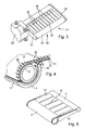
- Fig. 3 shows a further embodiment of the invention, namely a Cassette 21 with a flanged actuator 22.
- the cassette is with respect to its housing 23 and the two side parts 24, 25 similar to built the previous embodiments.
- the roller belt 26 is because that Window 27 is almost completely open, only by a narrow strip too recognize.
- the roller belt 26 is thus within the housing 23.
- Die Air flow direction is indicated by an arrow 28, d. H. the air pushes the roller belt 26 from the inside against the housing 23 and their Grids 29.
- the servomotor 22 is preferably as a geared motor or designed as a so-called flat drive, whose not shown Output shaft coaxial with the not visible here axis of the drive shaft for the roller belt 26 runs.
- the attachment of the servomotor 22 takes place preferably via the side part 24.
- Fig. 4 shows an enlarged section of the roller belt 2 in the region of Drive shaft 6 as shown in Fig. 2, where largely the same reference numbers are used.
- the drive shaft 6, the is shown in dashed lines, is located in the hollow cylindrical portion. 4 of the housing 3, wherein this wood cylinder 4 is not closed, but in Direction housing center is open.
- the wall of the hollow cylinder 4 runs in a resilient tongue 30 having a radius R out, above which introduced the roller belt 2 in the hollow cylindrical portion 4 and is led out again.
- the endless roller belt 2 has an upper layer 31 and a lower layer 32, which move in opposite directions.
- the Rolling tape 2 wraps around 3 ⁇ 4 of the circumference of the drive shaft 6 and is stretched by the resilient tongue 30.
- the tongue 30 thus replaces one Tensioner.
- On the circumference of the drive shaft 6 is a knob-shaped Gearing 20 provided in a corresponding perforation 18 in Edge region of the roller belt 2 engages.
- Fig. 5 shows the roller belt 2 as an endless belt, d. H. with the upper layer 31 and the lower layer 32, which merge into each other and thus one form a closed loop.
- the roller belt 2 instead of the above-described knob-like toothing 20 on the Drive shaft 6 in conjunction with the perforation 18 of the roller belt 2 can the roller belt 2 also with its two ends to the drive shaft. 6 be attached by placing the roller tape ends either in a longitudinal direction running slot clamped or in the longitudinal direction of the drive shaft. 6 be welded with this. The adjustment for the roller conveyor is then depending on the circumference of the drive shaft or the wrap angle.
Abstract
Description
- Fig. 1
- eine Kassette mit Rolljalousie,
- Fig. 2
- die Kassette mit Rolljalousie in vormontiertem Zustand,
- Fig. 3
- die Kassette mit Rolljalousie und angeflanschtem Stellmotor,
- Fig. 4
- einen vergrößerten Ausschnitt von Antriebswelle und Rollband und
- Fig. 5
- das Rollband als Endlosband.
Claims (11)
- Steuereinrichtung zum Steuern von Luftströmen in Heizungsund/oder Klimaanlagen von Kraftfahrzeugen, bestehend aus einem Rahmen, der in die Heizungs- und/oder Klimaanlage einsetzbar ist und Steuermittel zum Verändern des Durchtrittsquerschnittes für die Luftströmung innerhalb des Rahmens aufweist, dadurch gekennzeichnet, dass die Steuermittel als Rolljalousie ausgebildet sind.
- Steuereinrichtung nach Anspruch 1, dadurch gekennzeichnet, dass der Rahmen als Kassette mit einer Antriebs- und einer Umlenkwelle ausgebildet ist, über welche die Rolljalousie geführt ist.
- Steuereinrichtung nach Anspruch 1 oder 2, dadurch gekennzeichnet, dass die Rolljalousie als endloses Rollband mit Aussparungen zur Freigabe des Durchtrittsquerschnittes ausgebildet ist.
- Steuermittel nach Anspruch 2 oder 3, dadurch gekennzeichnet, dass die Antriebswelle stirnseitig Verzahnungen aufweist, die in Perforationen des Rollbandes eingreifen.
- Steuereinrichtung nach Anspruch 2, 3 oder 4, dadurch gekennzeichnet, dass der Rahmen aus einem Gehäuse mit längsseitig offenen hohlzylindrischen Bereichen besteht, welche die Antriebs- und die Umlenkwelle mit Rolljalousie in sich aufnehmen und seitlich durch je ein Seitenteil abgeschlossen sind.
- Steuereinrichtung nach Anspruch 5, dadurch gekennzeichnet, dass der hohlzylindrische Bereich des Gehäuses eine elastisch ausgebildete Zunge aufweist, die als Spannelement für das Rollband ausgebildet ist.
- Steuereinrichtung nach Anspruch 5 oder 6, dadurch gekennzeichnet, dass das Gehäuse, die Seitenteile, die Antriebs- und die Umlenkwelle als Kunststoffteile ausgebildet und miteinander durch Clipsverbindungen zu einer Baueinheit verbunden sind.
- Steuereinrichtung nach Anspruch 5, 6 oder 7, dadurch gekennzeichnet, dass das Gehäuse einen freien Durchtrittsquerschnitt aufweist, der durch Gitterstäbe unterteilt ist.
- Steuereinrichtung nach einem der Ansprüche 2 bis 8, dadurch gekennzeichnet, dass an den Rahmen ein Stellmotor zum Verstellen der Antriebswelle angeflanscht ist.
- Steuereinrichtung nach Anspruch 9, dadurch gekennzeichnet, dass der Stellmotor koaxial zur Antriebswelle angeordnet ist.
- Steuereinrichtung nach Anspruch 10, dadurch gekennzeichnet, dass der Stellmotor in die als Hohlwelle ausgebildete Antriebswelle integriert ist.
Applications Claiming Priority (2)
| Application Number | Priority Date | Filing Date | Title |
|---|---|---|---|
| DE10213177 | 2002-03-23 | ||
| DE2002113177 DE10213177A1 (de) | 2002-03-23 | 2002-03-23 | Steuereinrichtung für Heizungs- und/oder Klimaanlagen |
Publications (3)
| Publication Number | Publication Date |
|---|---|
| EP1346859A2 true EP1346859A2 (de) | 2003-09-24 |
| EP1346859A3 EP1346859A3 (de) | 2004-02-04 |
| EP1346859B1 EP1346859B1 (de) | 2006-11-29 |
Family
ID=27771522
Family Applications (1)
| Application Number | Title | Priority Date | Filing Date |
|---|---|---|---|
| EP03006571A Expired - Fee Related EP1346859B1 (de) | 2002-03-23 | 2003-03-24 | Steuereinrichtung für Heizungs- und/oder Klimaanlagen |
Country Status (3)
| Country | Link |
|---|---|
| EP (1) | EP1346859B1 (de) |
| DE (2) | DE10213177A1 (de) |
| ES (1) | ES2275966T3 (de) |
Cited By (8)
| Publication number | Priority date | Publication date | Assignee | Title |
|---|---|---|---|---|
| EP1369269A3 (de) * | 2002-06-05 | 2005-03-16 | Behr GmbH & Co. KG | Vorrichtung zur Steuerung eines Luftstroms, insbesondere für eine Heizungs- oder Klimaanlage von Kraftfahrzeugen |
| EP1522435A1 (de) * | 2003-10-08 | 2005-04-13 | Behr GmbH & Co. KG | Vorrichtung zum Verschliessen und Freigeben von Luftdurchtritts-Öffnungen und Klimaanlage mit einer derartigen Vorrichtung |
| EP1630014A1 (de) * | 2004-08-27 | 2006-03-01 | Delphi Technologies, Inc. | Seitlich geführte Rolljalousie-Steuermittel |
| EP1630017A3 (de) * | 2004-08-27 | 2006-03-29 | Delphi Technologies, Inc. | Rolljalousie-Steuermittel |
| DE102008004188A1 (de) | 2008-01-11 | 2009-07-16 | Behr Gmbh & Co. Kg | Rollband für eine Steuereinrichtung für Heizungs- und/oder Klimaanlagen |
| DE102008004187A1 (de) | 2008-01-11 | 2009-07-16 | Behr Gmbh & Co. Kg | Steuereinrichtung für Heizungs- und/oder Klimaanlagen |
| US20140179213A1 (en) * | 2012-12-26 | 2014-06-26 | Kia Motors Corporation | Control door for air conditioner |
| CN104417312A (zh) * | 2013-09-09 | 2015-03-18 | 现代自动车株式会社 | 车辆的主动式风门系统 |
Families Citing this family (3)
| Publication number | Priority date | Publication date | Assignee | Title |
|---|---|---|---|---|
| DE10343695A1 (de) * | 2003-09-18 | 2005-04-21 | Behr Gmbh & Co Kg | Fahrzeug-Klimatisierungsvorrichtung |
| DE102008031883B4 (de) | 2008-07-08 | 2017-10-26 | Mahle International Gmbh | Steuereinrichtung |
| DE202010014871U1 (de) | 2010-11-02 | 2011-01-05 | Behr Gmbh & Co. Kg | Kraftfahrzeugklimaanlage |
Citations (3)
| Publication number | Priority date | Publication date | Assignee | Title |
|---|---|---|---|---|
| DE3514358A1 (de) | 1985-04-20 | 1986-10-23 | Süddeutsche Kühlerfabrik Julius Fr. Behr GmbH & Co KG, 7000 Stuttgart | Vorrichtung zum wahlweisen absperren oder vollstaendigem oder teilweisem freigeben von luftstroemungswegen |
| EP0705725A1 (de) | 1994-10-07 | 1996-04-10 | Nippondenso Co., Ltd. | Klimaanlage mit einer Luftklappe aus Folie |
| DE4442000A1 (de) | 1994-11-28 | 1996-05-30 | Behr Gmbh & Co | Heizungs- und/oder Klimaeinrichtung |
Family Cites Families (6)
| Publication number | Priority date | Publication date | Assignee | Title |
|---|---|---|---|---|
| US5160115A (en) * | 1991-12-19 | 1992-11-03 | Nippondenso Co., Ltd. | Device for operating a damper in an air conditioning system for a vehicle |
| FR2746715B1 (fr) * | 1996-03-29 | 1998-05-22 | Valeo Climatisation | Dispositif de commande d'un flux d'air, en particulier pour une installation de chauffage et/ou climatisation de vehicule automobile |
| FR2752047B1 (fr) * | 1996-07-30 | 1998-10-09 | Valeo Climatisation | Dispositif du type a film enroule pour la commande d'un flux d'air, en particulier pour vehicule automobile |
| DE19717413C1 (de) * | 1997-04-25 | 1998-05-28 | Mc Micro Compact Car Ag | Belüftungseinrichtung für Fahrgastzellen von Fahrzeugen |
| GB2324600B (en) * | 1997-04-25 | 1999-03-10 | Mc Micro Compact Car Ag | Ventilation device for passenger cells of vehicles |
| US6273811B1 (en) * | 2000-01-21 | 2001-08-14 | Delphi Technologies, Inc. | Dual film belt vehicle air conditioning system |
-
2002
- 2002-03-23 DE DE2002113177 patent/DE10213177A1/de not_active Withdrawn
-
2003
- 2003-03-24 DE DE50305806T patent/DE50305806D1/de not_active Expired - Lifetime
- 2003-03-24 EP EP03006571A patent/EP1346859B1/de not_active Expired - Fee Related
- 2003-03-24 ES ES03006571T patent/ES2275966T3/es not_active Expired - Lifetime
Patent Citations (3)
| Publication number | Priority date | Publication date | Assignee | Title |
|---|---|---|---|---|
| DE3514358A1 (de) | 1985-04-20 | 1986-10-23 | Süddeutsche Kühlerfabrik Julius Fr. Behr GmbH & Co KG, 7000 Stuttgart | Vorrichtung zum wahlweisen absperren oder vollstaendigem oder teilweisem freigeben von luftstroemungswegen |
| EP0705725A1 (de) | 1994-10-07 | 1996-04-10 | Nippondenso Co., Ltd. | Klimaanlage mit einer Luftklappe aus Folie |
| DE4442000A1 (de) | 1994-11-28 | 1996-05-30 | Behr Gmbh & Co | Heizungs- und/oder Klimaeinrichtung |
Cited By (10)
| Publication number | Priority date | Publication date | Assignee | Title |
|---|---|---|---|---|
| EP1369269A3 (de) * | 2002-06-05 | 2005-03-16 | Behr GmbH & Co. KG | Vorrichtung zur Steuerung eines Luftstroms, insbesondere für eine Heizungs- oder Klimaanlage von Kraftfahrzeugen |
| EP1522435A1 (de) * | 2003-10-08 | 2005-04-13 | Behr GmbH & Co. KG | Vorrichtung zum Verschliessen und Freigeben von Luftdurchtritts-Öffnungen und Klimaanlage mit einer derartigen Vorrichtung |
| EP1630014A1 (de) * | 2004-08-27 | 2006-03-01 | Delphi Technologies, Inc. | Seitlich geführte Rolljalousie-Steuermittel |
| EP1630017A3 (de) * | 2004-08-27 | 2006-03-29 | Delphi Technologies, Inc. | Rolljalousie-Steuermittel |
| US7371161B2 (en) | 2004-08-27 | 2008-05-13 | Delphi Technologies, Inc. | Sliding film valve driven at edge |
| US7527551B2 (en) | 2004-08-27 | 2009-05-05 | Delphi Technologies, Inc. | Sliding valve, especially for heating, ventilation and air conditioning system |
| DE102008004188A1 (de) | 2008-01-11 | 2009-07-16 | Behr Gmbh & Co. Kg | Rollband für eine Steuereinrichtung für Heizungs- und/oder Klimaanlagen |
| DE102008004187A1 (de) | 2008-01-11 | 2009-07-16 | Behr Gmbh & Co. Kg | Steuereinrichtung für Heizungs- und/oder Klimaanlagen |
| US20140179213A1 (en) * | 2012-12-26 | 2014-06-26 | Kia Motors Corporation | Control door for air conditioner |
| CN104417312A (zh) * | 2013-09-09 | 2015-03-18 | 现代自动车株式会社 | 车辆的主动式风门系统 |
Also Published As
| Publication number | Publication date |
|---|---|
| DE50305806D1 (de) | 2007-01-11 |
| DE10213177A1 (de) | 2003-10-02 |
| EP1346859A3 (de) | 2004-02-04 |
| ES2275966T3 (es) | 2007-06-16 |
| EP1346859B1 (de) | 2006-11-29 |
Similar Documents
| Publication | Publication Date | Title |
|---|---|---|
| EP0740617B1 (de) | Heizungs- und/oder klimaeinrichtung | |
| EP1256472A2 (de) | Sonnenrollo für ein Fahrzeugdach | |
| EP1532011B1 (de) | Steuereinrichtung mit rollbandkassette | |
| EP1346859B1 (de) | Steuereinrichtung für Heizungs- und/oder Klimaanlagen | |
| DE3514358C2 (de) | Vorrichtung zum wahlweisen Absperren oder vollständigem oder teilweisem Freigeben von wenigstens zwei Luftströmungswegen einer Heizungs- und/oder Klimaanlage | |
| EP1270286B1 (de) | Luftleitvorrichtung, insbesondere eines Fahrzeugs | |
| DE102007053531A1 (de) | Rolloeinrichtung | |
| DE19936688C2 (de) | Gebläseeinheit für die Klimaanlage eines Kraftfahrzeugs | |
| DE102019206739A1 (de) | Luftausströmer mit einer Luftregelklappe und einer Torsionsfeder | |
| DE19711679B4 (de) | Vorrichtung und Verfahren zur Regelung einer Luftströmung | |
| DE102008004189A1 (de) | Luftausströmer | |
| EP1344664B1 (de) | Luftmischeinrichtung | |
| DE19632147B4 (de) | Heiz- oder Klimaanlage | |
| DE19711822A1 (de) | Vorrichtung zur Steuerung eines Luftstroms, insbesondere für eine Heizungs- und/oder Klimaanlage von Kraftfahrzeugen | |
| DE19711209A1 (de) | Vorrichtung zur Steuerung eines Luftstroms, insbesondere für eine Heizungs- und/oder Klimaanlage von Kraftfahrzeugen | |
| EP1832450B1 (de) | Klappenanordnung, insbesondere für ein Kraftfahrzeug | |
| DE10105182B4 (de) | Schiebervorrichtung | |
| EP1369269B1 (de) | Vorrichtung zur Steuerung eines Luftstroms, insbesondere für eine Heizungs- oder Klimaanlage von Kraftfahrzeugen | |
| DE102005063235A1 (de) | Kraftfahrzeugbelüftungs- und Klimagerät | |
| DE19631024B4 (de) | Heiz- oder Klimaanlage | |
| DE19853932B4 (de) | Schlitzabdeckung einer Schaltvorrichtung | |
| DE19711821A1 (de) | Vorrichtung zur Steuerung eines Luftstroms, insbesondere für eine Heizungs- und/oder Klimaanlage von Kraftfahrzeugen | |
| EP2050598B1 (de) | Klappenanordnung, für eine Fahrzeug-Klimaanlage | |
| DE10351064A1 (de) | Fahrzeugklimaanlage | |
| WO2022069765A2 (de) | Luftführungssteuerung für ein kraftfahrzeug |
Legal Events
| Date | Code | Title | Description |
|---|---|---|---|
| PUAI | Public reference made under article 153(3) epc to a published international application that has entered the european phase |
Free format text: ORIGINAL CODE: 0009012 |
|
| AK | Designated contracting states |
Kind code of ref document: A2 Designated state(s): AT BE BG CH CY CZ DE DK EE ES FI FR GB GR HU IE IT LI LU MC NL PT RO SE SI SK TR |
|
| AX | Request for extension of the european patent |
Extension state: AL LT LV MK |
|
| PUAL | Search report despatched |
Free format text: ORIGINAL CODE: 0009013 |
|
| AK | Designated contracting states |
Kind code of ref document: A3 Designated state(s): AT BE BG CH CY CZ DE DK EE ES FI FR GB GR HU IE IT LI LU MC NL PT RO SE SI SK TR |
|
| AX | Request for extension of the european patent |
Extension state: AL LT LV MK |
|
| 17P | Request for examination filed |
Effective date: 20040804 |
|
| AKX | Designation fees paid |
Designated state(s): DE ES FR GB IT SE |
|
| 17Q | First examination report despatched |
Effective date: 20041019 |
|
| RAP1 | Party data changed (applicant data changed or rights of an application transferred) |
Owner name: BEHR GMBH & CO. KG |
|
| GRAP | Despatch of communication of intention to grant a patent |
Free format text: ORIGINAL CODE: EPIDOSNIGR1 |
|
| GRAS | Grant fee paid |
Free format text: ORIGINAL CODE: EPIDOSNIGR3 |
|
| GRAA | (expected) grant |
Free format text: ORIGINAL CODE: 0009210 |
|
| AK | Designated contracting states |
Kind code of ref document: B1 Designated state(s): DE ES FR GB IT SE |
|
| REG | Reference to a national code |
Ref country code: GB Ref legal event code: FG4D Free format text: NOT ENGLISH |
|
| REF | Corresponds to: |
Ref document number: 50305806 Country of ref document: DE Date of ref document: 20070111 Kind code of ref document: P |
|
| REG | Reference to a national code |
Ref country code: SE Ref legal event code: TRGR |
|
| GBT | Gb: translation of ep patent filed (gb section 77(6)(a)/1977) |
Effective date: 20070208 |
|
| REG | Reference to a national code |
Ref country code: ES Ref legal event code: FG2A Ref document number: 2275966 Country of ref document: ES Kind code of ref document: T3 |
|
| ET | Fr: translation filed | ||
| PLBE | No opposition filed within time limit |
Free format text: ORIGINAL CODE: 0009261 |
|
| STAA | Information on the status of an ep patent application or granted ep patent |
Free format text: STATUS: NO OPPOSITION FILED WITHIN TIME LIMIT |
|
| 26N | No opposition filed |
Effective date: 20070830 |
|
| PGFP | Annual fee paid to national office [announced via postgrant information from national office to epo] |
Ref country code: ES Payment date: 20080328 Year of fee payment: 6 |
|
| PGFP | Annual fee paid to national office [announced via postgrant information from national office to epo] |
Ref country code: IT Payment date: 20080318 Year of fee payment: 6 Ref country code: SE Payment date: 20080320 Year of fee payment: 6 |
|
| PGFP | Annual fee paid to national office [announced via postgrant information from national office to epo] |
Ref country code: GB Payment date: 20090326 Year of fee payment: 7 |
|
| EUG | Se: european patent has lapsed | ||
| REG | Reference to a national code |
Ref country code: ES Ref legal event code: FD2A Effective date: 20090325 |
|
| PGFP | Annual fee paid to national office [announced via postgrant information from national office to epo] |
Ref country code: FR Payment date: 20100408 Year of fee payment: 8 |
|
| PG25 | Lapsed in a contracting state [announced via postgrant information from national office to epo] |
Ref country code: ES Free format text: LAPSE BECAUSE OF NON-PAYMENT OF DUE FEES Effective date: 20090325 |
|
| GBPC | Gb: european patent ceased through non-payment of renewal fee |
Effective date: 20100324 |
|
| PG25 | Lapsed in a contracting state [announced via postgrant information from national office to epo] |
Ref country code: GB Free format text: LAPSE BECAUSE OF NON-PAYMENT OF DUE FEES Effective date: 20100324 Ref country code: IT Free format text: LAPSE BECAUSE OF NON-PAYMENT OF DUE FEES Effective date: 20090324 |
|
| PG25 | Lapsed in a contracting state [announced via postgrant information from national office to epo] |
Ref country code: SE Free format text: LAPSE BECAUSE OF NON-PAYMENT OF DUE FEES Effective date: 20090325 |
|
| REG | Reference to a national code |
Ref country code: FR Ref legal event code: ST Effective date: 20111130 |
|
| PG25 | Lapsed in a contracting state [announced via postgrant information from national office to epo] |
Ref country code: FR Free format text: LAPSE BECAUSE OF NON-PAYMENT OF DUE FEES Effective date: 20110331 |
|
| REG | Reference to a national code |
Ref country code: DE Ref legal event code: R082 Ref document number: 50305806 Country of ref document: DE Representative=s name: GRAUEL, ANDREAS, DIPL.-PHYS. DR. RER. NAT., DE |
|
| REG | Reference to a national code |
Ref country code: DE Ref legal event code: R082 Ref document number: 50305806 Country of ref document: DE Representative=s name: GRAUEL, ANDREAS, DIPL.-PHYS. DR. RER. NAT., DE Effective date: 20150318 Ref country code: DE Ref legal event code: R081 Ref document number: 50305806 Country of ref document: DE Owner name: MAHLE INTERNATIONAL GMBH, DE Free format text: FORMER OWNER: BEHR GMBH & CO. KG, 70469 STUTTGART, DE Effective date: 20150318 |
|
| PGFP | Annual fee paid to national office [announced via postgrant information from national office to epo] |
Ref country code: DE Payment date: 20200514 Year of fee payment: 18 |
|
| REG | Reference to a national code |
Ref country code: DE Ref legal event code: R119 Ref document number: 50305806 Country of ref document: DE |
|
| PG25 | Lapsed in a contracting state [announced via postgrant information from national office to epo] |
Ref country code: DE Free format text: LAPSE BECAUSE OF NON-PAYMENT OF DUE FEES Effective date: 20211001 |