EP1346710A1 - Sprunggelenkorthese - Google Patents
Sprunggelenkorthese Download PDFInfo
- Publication number
- EP1346710A1 EP1346710A1 EP03006260A EP03006260A EP1346710A1 EP 1346710 A1 EP1346710 A1 EP 1346710A1 EP 03006260 A EP03006260 A EP 03006260A EP 03006260 A EP03006260 A EP 03006260A EP 1346710 A1 EP1346710 A1 EP 1346710A1
- Authority
- EP
- European Patent Office
- Prior art keywords
- ankle
- area
- connections
- subchambers
- chamber
- Prior art date
- Legal status (The legal status is an assumption and is not a legal conclusion. Google has not performed a legal analysis and makes no representation as to the accuracy of the status listed.)
- Granted
Links
Images


Classifications
-
- A—HUMAN NECESSITIES
- A61—MEDICAL OR VETERINARY SCIENCE; HYGIENE
- A61F—FILTERS IMPLANTABLE INTO BLOOD VESSELS; PROSTHESES; DEVICES PROVIDING PATENCY TO, OR PREVENTING COLLAPSING OF, TUBULAR STRUCTURES OF THE BODY, e.g. STENTS; ORTHOPAEDIC, NURSING OR CONTRACEPTIVE DEVICES; FOMENTATION; TREATMENT OR PROTECTION OF EYES OR EARS; BANDAGES, DRESSINGS OR ABSORBENT PADS; FIRST-AID KITS
- A61F5/00—Orthopaedic methods or devices for non-surgical treatment of bones or joints; Nursing devices ; Anti-rape devices
- A61F5/01—Orthopaedic devices, e.g. long-term immobilising or pressure directing devices for treating broken or deformed bones such as splints, casts or braces
- A61F5/0102—Orthopaedic devices, e.g. long-term immobilising or pressure directing devices for treating broken or deformed bones such as splints, casts or braces specially adapted for correcting deformities of the limbs or for supporting them; Ortheses, e.g. with articulations
- A61F5/012—Orthopaedic devices, e.g. long-term immobilising or pressure directing devices for treating broken or deformed bones such as splints, casts or braces specially adapted for correcting deformities of the limbs or for supporting them; Ortheses, e.g. with articulations inflatable
-
- A—HUMAN NECESSITIES
- A61—MEDICAL OR VETERINARY SCIENCE; HYGIENE
- A61F—FILTERS IMPLANTABLE INTO BLOOD VESSELS; PROSTHESES; DEVICES PROVIDING PATENCY TO, OR PREVENTING COLLAPSING OF, TUBULAR STRUCTURES OF THE BODY, e.g. STENTS; ORTHOPAEDIC, NURSING OR CONTRACEPTIVE DEVICES; FOMENTATION; TREATMENT OR PROTECTION OF EYES OR EARS; BANDAGES, DRESSINGS OR ABSORBENT PADS; FIRST-AID KITS
- A61F5/00—Orthopaedic methods or devices for non-surgical treatment of bones or joints; Nursing devices ; Anti-rape devices
- A61F5/01—Orthopaedic devices, e.g. long-term immobilising or pressure directing devices for treating broken or deformed bones such as splints, casts or braces
- A61F5/0102—Orthopaedic devices, e.g. long-term immobilising or pressure directing devices for treating broken or deformed bones such as splints, casts or braces specially adapted for correcting deformities of the limbs or for supporting them; Ortheses, e.g. with articulations
- A61F5/0104—Orthopaedic devices, e.g. long-term immobilising or pressure directing devices for treating broken or deformed bones such as splints, casts or braces specially adapted for correcting deformities of the limbs or for supporting them; Ortheses, e.g. with articulations without articulation
- A61F5/0111—Orthopaedic devices, e.g. long-term immobilising or pressure directing devices for treating broken or deformed bones such as splints, casts or braces specially adapted for correcting deformities of the limbs or for supporting them; Ortheses, e.g. with articulations without articulation for the feet or ankles
Definitions
- the invention relates to an ankle orthosis with two over the ankles the lower leg along the thighs that pass under the foot a flexible web connected and with a fluid-containing cushion chambers are provided.
- the invention is based, an ankle brace with the task To create fluid-containing cushioning chambers where the ankle is particularly special is exposed to low pressure and also when walking as a result of it associated rhythmic pressure effect on the upholstery one in the direction Knee-reducing surface pressure arises, through which the outflow of blood is promoted from the ankle.
- the latter is particularly important when it comes to treating swelling in the area of the Ankle.
- the problem is solved by having a single cushion chamber per leg is provided with a longitudinal division, each in the area of an ankle a zone of reduced extensibility and thus one compared to the ankle this receiving recess forms, and the web of such elastic Material exists that this when walking and unrolling the Foot and rhythmic pumping of the upholstery chambers intermittently lengthened and shortened.
- This ankle orthosis according to the invention initially leads to the advantage of a Simplified production, since the ankle orthosis with each leg only one upholstery chamber needs, so that for the respective upholstery chamber too only one inlet valve is required.
- the desired different surface pressure is used in spite of the use of only a single cushion chamber Leg achieved in that each cushioning chamber has a longitudinal division, the zone of reduced extensibility in the area of the ankle creates because of the longitudinal subdivision in this area the cushion chamber Indentation forms, in which the ankle can protrude relatively free of pressure.
- connections arranged opposite walls of this cushion chamber manufactured that run along the longitudinal division.
- These connections are expediently formed by welding in accordance with current technology. However, it should be noted that of course the connections also e.g. can be brought about by gluing.
- a particularly favorable design of the longitudinal division results from that two routes of connections are provided for their implementation, which run in a V-shape such that the two sections meet in the area of the ankle and aim towards the knee so far apart that, going out from the area of the ankle, next to this two subchambers and in Transition of the stretches towards the knee three adjacent subchambers are formed, the cross section of which decreases in the filled state is the cross section of each of the two subchambers in the area of the ankle.
- This design of the connections results in the area of the ankle in the Effect two subchambers next to the ankle and in the wider area the leg in the transition of the stretches towards the knee three side by side lying subchambers, all part of the single padding chamber per leg are and are thus also filled when filling the cushion chamber and their internal pressure towards the entire area of the Can also compensate for the upholstery chamber.
- This design results in addition to the ankle an area with two larger subchambers and in the area at the end of the "V" formed by the connections, three next to each other Subchambers whose cross-section when filled is smaller than the cross-section of the two subchambers in the area of the ankle.
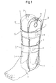
- the ankle brace placed on a foot in FIG. 1 has the two Legs 1 and 2, which extend from the sole of the foot towards the knee and connected in the area of the sole of the foot by the web 3, which is invisible in FIG are.
- the design and function of the web 3 is related to of Figure 2 discussed in more detail.
- Both legs 1 and 2 serve the two belts 4 and 5, which on the leg 2 are fixed and overlap in the area of the leg 1.
- the one below lying part 6 and 7 is equipped with a Velcro part 8 and 9, respectively with a corresponding part on the inner side of the overlapping end of the Belt 4 or 5 acts together in a known manner. That kind of fixing an ankle orthosis equipped with two legs is known.
- the leg 1 is connected to the continuous cushion chamber 10, which at put on ankle orthosis between the leg 1 and the leg of the wearer lies.
- the cushion chamber 10 is inflated via the valve 11, which is known in the art Is designed. Instead of air to inflate the upholstery chamber 10 other fluid can of course be used, but be on it noted that for the purposes described here, primarily air is a suitable medium.
- the one on the other side of the leg Leg 2 carries the cushion chamber 12, which is filled via the valve 13. insofar so here are mirror images of leg 1 and padding chamber 2 Conditions before.
- FIG. 2 shows the ankle orthosis according to FIG. 1 in a top view shown the shin of the wearer, so that the two legs 1 and 2 directly with their edges 14, 15 are visible.
- Legs 1 and 2 are in the area the sole of the foot, as already described in connection with FIG. 1, by the Web 3 connected, which consists of an elastic material.
- the legs 1 and 2 have the edges 14 and 15 which merge into the web 3.
- the bridge 3 itself as can be seen, is thinner than the edge 14 or 15, which is due to the two weakening points 16 and 17 in the region of the transition of the web 3 in the legs 1 and 2 can be seen.
- the material of the web 3 can be e.g.
- thermoplastic elastomer that is incorporated into the material of the legs 1 and 2 passes over the two weakening points 16 and 17.
- This design has the consequence that there is a result of walking and rolling of the foot lateral pushing apart of the legs 1 and 2 in the area of the sole of the foot allows without complaints, namely by the web 3 correspondingly elastic yields what is indicated by the two dashed arrangements in the area of the web 3 is indicated, denoted by the areas 3 'and 3 ".
- Figure 3 shows the ankle orthosis according to Figure 2 rotated by 90 °, the Viewer of the leg 1 facing is visible.
- Figure 3 clearly shows that seen from the viewer behind the leg 1, the cushion chamber 10 is arranged, which therefore rests on the leg of the wearer.
- FIG. 4 shows a section along the line IV-IV from Figure 2, wherein therefore the web 3 is drawn in section. 4 shows the viewer accordingly the inside of the cushion chamber 10 with their Valve 11 and the leg 1 drawn in dashed lines behind it.
- the upholstery chamber 10 contains the single chamber space 18 in which via the valve 11 and the channel 35 air is blown in.
- the channel 35 is laid accordingly Welds formed.
- FIG. 5 shows a variant of the representation according to FIG there is that here the welding spots 19 lying in series by the two Welds 27 and 28 are formed, which in effect effect the same as the welding points 19 lying on the lines 20 and 21.
- FIG. 6 shows a section along the line VI-VI from FIG. 4.
- the So the cut runs in the area where the lines 20 and 21 converge, where the ankle of the ankle orthosis is located.
- the welding points 19 present there or the weld seams which have converged 27 and 28 according to FIG. 5 there is the indentation 29, into which an ankle can protrude without being subjected to any particular pressure there.
- FIG. 7 shows a section along line VII-VII from FIG largely corresponds to the representation in FIG. 6, but with the change, that the section VII-VII through the area of the subchambers 24, 25 and 26 runs, which are connected to the common chamber space 18 and be fed with air via the feed channel 35.
Landscapes
- Health & Medical Sciences (AREA)
- Vascular Medicine (AREA)
- Animal Behavior & Ethology (AREA)
- Engineering & Computer Science (AREA)
- Biomedical Technology (AREA)
- Heart & Thoracic Surgery (AREA)
- Nursing (AREA)
- Life Sciences & Earth Sciences (AREA)
- Orthopedic Medicine & Surgery (AREA)
- General Health & Medical Sciences (AREA)
- Public Health (AREA)
- Veterinary Medicine (AREA)
- Orthopedics, Nursing, And Contraception (AREA)
- Prostheses (AREA)
- Rehabilitation Tools (AREA)
Abstract
Description
- Figur 1
- eine an einem linken Fuß angebrachte Sprunggelenkorthese in perspektivischer Sicht;
- Figur 2
- die gleiche Sprunggelenkorthese in einer Draufsicht auf das Schienbein;
- Figur 3
- die Gestaltung gemäß Figur 2 um 90° gedreht;
- Figur 4
- eine Polsterkammer im Schnitt mit durch Schweißpunkte gebildete Verbindungen;
- Figur 5
- eine Polsterkammer im Schnitt mit durch Schweißnähte gebildete Verbindungen;
- Figur 6
- einen Schnitt durch die Anordnung gemäß Figur 4 längs der Linie VI-VI;
- Figur 7
- einen Schnitt durch die Anordnung gemäß Figur 4 längs der Linie VII-VII.
Claims (6)
- Sprunggelenkorthese mit zwei über die Knöchel den Unterschenkel entlang verlaufenden Schenkeln 1,2, die unter dem Fuß durch einen biegsamen Steg 2 verbunden und mit ein Fluid enthaltenden Polsterkammern 10,12 versehen sind, dadurch gekennzeichnet, dass pro Schenkel 1,2 eine einzige Polsterkammer 10,12 mit einer Längsunterteilung 20,21; 27,28 vorgesehen ist, die jeweils im Bereich eines Knöchels eine Zone reduzierter Ausdehnbarkeit und damit gegenüber dem Knöchel eine diesen aufnehmende Einbuchtung 29 bildet, und der Steg 3 aus derart zugelastischem Material besteht, dass dieser beim Gehen und dabei erfolgendem Abrollen des Fußes sowie rhythmischem Pumpen der Polsterkammern 10,12 sich intermittierend verlängert und verkürzt.
- Sprunggelenkorthese nach Anspruch 1, dadurch gekennzeichnet, dass die Längsunterteilung durch zwischen gegenüberliegenden Wänden 31,31 jeder Polsterkammer angeordnete Verbindungen gestaltet ist, die entlang der Längsunterteilung verlaufen.
- Sprunggelenkorthese nach Anspruch 2, dadurch gekennzeichnet, dass die Verbindungen durch Verschweißen gebildet sind.
- Sprunggelenkorthese nach Anspruch 3, dadurch gekennzeichnet, dass die Verbindungen durch in Reihe liegende Schweißpunkte 19 gebildet sind.
- Sprunggelenkorthese nach Anspruch 3, dadurch gekennzeichnet, dass die Verbindungen durch Schweißnähte 27,28 gebildet sind.
- Sprunggelenkorthese nach einem der Ansprüche 2 bis 5, dadurch gekennzeichnet, dass zwei Strecken 20,21 von Verbindungen vorgesehen sind, die derart V-förmig verlaufen, dass die beiden Strecken im Bereich des Knöchels zusammenlaufen und in Richtung zum Knie so weit auseinander streben, dass, ausgehend vom Bereich des Knöchels, neben diesem zwei Unterkammern 22,23 und im Übergang der Strecken in Richtung zum Knie drei nebeneinanderliegende Unterkammern 24,25,26 gebildet sind, deren Querschnitt im gefüllten Zustand abnehmend geringer ist als der Querschnitt jeder der beiden Unterkammern 22,23 im Bereich des Knöchels.
Applications Claiming Priority (2)
| Application Number | Priority Date | Filing Date | Title |
|---|---|---|---|
| DE10213238A DE10213238B4 (de) | 2002-03-22 | 2002-03-22 | Sprunggelenkorthese |
| DE10213238 | 2002-03-22 |
Publications (2)
| Publication Number | Publication Date |
|---|---|
| EP1346710A1 true EP1346710A1 (de) | 2003-09-24 |
| EP1346710B1 EP1346710B1 (de) | 2006-10-25 |
Family
ID=27771524
Family Applications (1)
| Application Number | Title | Priority Date | Filing Date |
|---|---|---|---|
| EP03006260A Expired - Lifetime EP1346710B1 (de) | 2002-03-22 | 2003-03-21 | Sprunggelenkorthese |
Country Status (4)
| Country | Link |
|---|---|
| US (1) | US6875190B2 (de) |
| EP (1) | EP1346710B1 (de) |
| DE (1) | DE10213238B4 (de) |
| ES (1) | ES2271404T3 (de) |
Cited By (3)
| Publication number | Priority date | Publication date | Assignee | Title |
|---|---|---|---|---|
| USD696409S1 (en) | 2012-09-17 | 2013-12-24 | Shock Doctor, Inc. | Ankle brace |
| US11259947B2 (en) | 2016-06-03 | 2022-03-01 | Shock Doctor, Inc. | Ankle brace devices, systems and methods |
| US12053405B2 (en) | 2018-09-27 | 2024-08-06 | Shock Doctor, Inc. | Ankle brace devices, systems, and methods |
Families Citing this family (9)
| Publication number | Priority date | Publication date | Assignee | Title |
|---|---|---|---|---|
| WO2006079095A2 (en) * | 2005-01-21 | 2006-07-27 | Aircast Llc | Brace having inflatable support |
| US20070049855A1 (en) * | 2005-08-25 | 2007-03-01 | Restorative Care Of America Incorporated | Ankle stirrup brace |
| EP2076224B1 (de) * | 2006-09-12 | 2016-08-24 | Boa Technology, Inc. | Verschlusssystem für gurte, schutzkleidung und ähnliche artikel |
| US20090227927A1 (en) * | 2008-03-10 | 2009-09-10 | Frazer Michael J | Orthopedic walking brace |
| US8622946B2 (en) * | 2008-12-02 | 2014-01-07 | Ossur Hf | Ankle brace |
| USD620124S1 (en) * | 2009-09-14 | 2010-07-20 | Ossur Hf | Orthopedic device |
| US8979783B2 (en) | 2012-02-03 | 2015-03-17 | Tate L. Viehweg | Orthopedic devices, systems, and methods of use |
| CN105771226B (zh) * | 2016-04-19 | 2018-06-22 | 东华大学 | 一种防护踝关节内翻的半刚性踝护具及其制备方法 |
| KR102395943B1 (ko) * | 2020-03-31 | 2022-05-12 | 서울대학교병원 | 보행 재활 훈련용 하지 로봇 보조기와 그 제어 방법 및 자율 주행 캐리어 |
Citations (5)
| Publication number | Priority date | Publication date | Assignee | Title |
|---|---|---|---|---|
| US4977891A (en) * | 1989-11-08 | 1990-12-18 | Royce Medical Company | Variable support ankle brace |
| US5125400A (en) | 1985-12-16 | 1992-06-30 | Aircast Incorporated | Ankle brace having multiple inflatable aircells |
| US5348530A (en) * | 1993-07-29 | 1994-09-20 | Royce Medical Company | Pneumatic ankle brace with bladder and pump arrangement |
| US5389065A (en) * | 1993-06-15 | 1995-02-14 | Aircast, Inc. | Ankle brace with ATF compression |
| US5489259A (en) * | 1993-10-27 | 1996-02-06 | Sundance Enterprises, Inc. | Pressure-normalizing single-chambered static pressure device for supporting and protecting a body extremity |
Family Cites Families (16)
| Publication number | Priority date | Publication date | Assignee | Title |
|---|---|---|---|---|
| DE306226C (de) | ||||
| AT306226B (de) * | 1968-12-05 | 1973-03-26 | Josef Swoboda Dr Med | Vorrichtung zum Behandeln hypostatischer Beinleiden |
| DE2238961A1 (de) * | 1972-08-08 | 1974-02-28 | Lange Asschenfeldt Henning Dr | Pneumatische kompressionsbinde |
| CA1133349A (en) * | 1978-04-06 | 1982-10-12 | Glenn W. Johnson, Jr. | Ankle brace |
| US5242379A (en) * | 1990-07-02 | 1993-09-07 | Exoflex, Inc. | Ankle brace with floating pivot hinge |
| US5250021A (en) * | 1992-02-10 | 1993-10-05 | Chang Shin Ju D | Foot and ankle brace |
| US5352189A (en) * | 1992-02-19 | 1994-10-04 | Tecnol Medical Products, Inc. | Ankle brace walker |
| US5209722A (en) * | 1992-03-26 | 1993-05-11 | Joint Solutions, Inc. | Ankle brace |
| US5637077A (en) * | 1995-10-30 | 1997-06-10 | Smith & Nephew Casting, Inc. | Custom-molded ankle brace |
| US5630792A (en) * | 1995-12-07 | 1997-05-20 | Deroyal Industries, Inc. | Ankle brace |
| US6056713A (en) * | 1996-05-31 | 2000-05-02 | Hayashi; Melvin M. | Moldable custom-fitted ankle brace |
| AU739674B2 (en) * | 1996-08-29 | 2001-10-18 | Royce Medical Company | Comfortable orthopaedic support and the method of making the same |
| NL1004931C2 (nl) * | 1997-01-05 | 1998-07-08 | Floor Schrijver | Middelzware enkelsteun. |
| US6146350A (en) * | 1998-01-30 | 2000-11-14 | Active Ankle Systems, Inc. | Ankle brace with removable single piece hinge |
| US6053884A (en) * | 1999-02-18 | 2000-04-25 | Athlete Protection Gear, Llc | Ankle brace with cuff |
| US6602215B1 (en) * | 2002-07-03 | 2003-08-05 | Douglas H. Richie, Jr. | Ankle brace with arch sling support |
-
2002
- 2002-03-22 DE DE10213238A patent/DE10213238B4/de not_active Expired - Lifetime
-
2003
- 2003-03-21 EP EP03006260A patent/EP1346710B1/de not_active Expired - Lifetime
- 2003-03-21 US US10/392,962 patent/US6875190B2/en not_active Expired - Lifetime
- 2003-03-21 ES ES03006260T patent/ES2271404T3/es not_active Expired - Lifetime
Patent Citations (5)
| Publication number | Priority date | Publication date | Assignee | Title |
|---|---|---|---|---|
| US5125400A (en) | 1985-12-16 | 1992-06-30 | Aircast Incorporated | Ankle brace having multiple inflatable aircells |
| US4977891A (en) * | 1989-11-08 | 1990-12-18 | Royce Medical Company | Variable support ankle brace |
| US5389065A (en) * | 1993-06-15 | 1995-02-14 | Aircast, Inc. | Ankle brace with ATF compression |
| US5348530A (en) * | 1993-07-29 | 1994-09-20 | Royce Medical Company | Pneumatic ankle brace with bladder and pump arrangement |
| US5489259A (en) * | 1993-10-27 | 1996-02-06 | Sundance Enterprises, Inc. | Pressure-normalizing single-chambered static pressure device for supporting and protecting a body extremity |
Cited By (4)
| Publication number | Priority date | Publication date | Assignee | Title |
|---|---|---|---|---|
| USD696409S1 (en) | 2012-09-17 | 2013-12-24 | Shock Doctor, Inc. | Ankle brace |
| USD708344S1 (en) | 2012-09-17 | 2014-07-01 | Shock Doctor, Inc. | Ankle brace |
| US11259947B2 (en) | 2016-06-03 | 2022-03-01 | Shock Doctor, Inc. | Ankle brace devices, systems and methods |
| US12053405B2 (en) | 2018-09-27 | 2024-08-06 | Shock Doctor, Inc. | Ankle brace devices, systems, and methods |
Also Published As
| Publication number | Publication date |
|---|---|
| US6875190B2 (en) | 2005-04-05 |
| EP1346710B1 (de) | 2006-10-25 |
| ES2271404T3 (es) | 2007-04-16 |
| DE10213238A1 (de) | 2003-10-30 |
| DE10213238B4 (de) | 2012-06-06 |
| US20040010214A1 (en) | 2004-01-15 |
Similar Documents
| Publication | Publication Date | Title |
|---|---|---|
| DE60126045T2 (de) | Kompressionsmanschette | |
| DE60017944T2 (de) | Orthopädische sprunggelenkstütze | |
| DE60315698T2 (de) | FUßGELENKORTHOSE | |
| DE69329472T2 (de) | Medizinisches gerät zur behandlung durch intermittierende kompression | |
| EP1086675B1 (de) | Kompressionsmanschette zur Behandlung von Beinleiden | |
| DE69523080T2 (de) | Knieorthese zur Behandlung von Osteoarthritis | |
| DE3686948T2 (de) | Aufblasbare stuetzschiene. | |
| EP1346710A1 (de) | Sprunggelenkorthese | |
| DE20219638U1 (de) | Aufblasbare Körper-Struktur für eine Luftmatratze | |
| DE2713627A1 (de) | Vorrichtung zum aufbringen eines pulsierenden drucks auf einen teil des menschlichen koerpers | |
| DE1879386U (de) | Fusspolster. | |
| DE102004004633A1 (de) | Kompressionsstützbandmaterial mit einer inneren Gewebezwischenlage | |
| DE2122907B2 (de) | In einem Schuh, Stiefel o.dgl. anzuordnendes Stützpolster | |
| EP1629811A1 (de) | Elastische Kniegelenkbandage | |
| DE10034354A1 (de) | Fußbandage | |
| EP0305999A1 (de) | Fussgelenk-Stützmanschette | |
| DE3511250A1 (de) | Bandage fuer menschen zur behandlung von erkrankungen oder verletzungen | |
| EP1284695B1 (de) | Orthopädische schiene und orthopädisches kleidungsstück | |
| DE20203275U1 (de) | Fußbandage | |
| DE69621426T2 (de) | Knieorthese mit einem die patella einfassenden, aufblasbarem kissen | |
| DE3415657C2 (de) | Fußgelenkbandage | |
| EP3117808B1 (de) | Vorrichtung zur vermeidung einer thrombose in den beinvenen | |
| DE10358146B4 (de) | Elastische Bandage und Verfahren zu deren Herstellung | |
| EP0751754B1 (de) | Knieorthese | |
| DE19844545B4 (de) | Gelenkorthese |
Legal Events
| Date | Code | Title | Description |
|---|---|---|---|
| PUAI | Public reference made under article 153(3) epc to a published international application that has entered the european phase |
Free format text: ORIGINAL CODE: 0009012 |
|
| AK | Designated contracting states |
Kind code of ref document: A1 Designated state(s): AT BE BG CH CY CZ DE DK EE ES FI FR GB GR HU IE IT LI LU MC NL PT RO SE SI SK TR |
|
| AX | Request for extension of the european patent |
Extension state: AL LT LV MK |
|
| 17P | Request for examination filed |
Effective date: 20030901 |
|
| AKX | Designation fees paid |
Designated state(s): ES FR GB IT |
|
| REG | Reference to a national code |
Ref country code: DE Ref legal event code: 8566 |
|
| RAP1 | Party data changed (applicant data changed or rights of an application transferred) |
Owner name: BAUERFEIND AG |
|
| GRAP | Despatch of communication of intention to grant a patent |
Free format text: ORIGINAL CODE: EPIDOSNIGR1 |
|
| GRAS | Grant fee paid |
Free format text: ORIGINAL CODE: EPIDOSNIGR3 |
|
| GRAA | (expected) grant |
Free format text: ORIGINAL CODE: 0009210 |
|
| AK | Designated contracting states |
Kind code of ref document: B1 Designated state(s): ES FR GB IT |
|
| REG | Reference to a national code |
Ref country code: GB Ref legal event code: FG4D Free format text: NOT ENGLISH |
|
| GBT | Gb: translation of ep patent filed (gb section 77(6)(a)/1977) |
Effective date: 20061025 |
|
| REG | Reference to a national code |
Ref country code: ES Ref legal event code: FG2A Ref document number: 2271404 Country of ref document: ES Kind code of ref document: T3 |
|
| ET | Fr: translation filed | ||
| PLBE | No opposition filed within time limit |
Free format text: ORIGINAL CODE: 0009261 |
|
| STAA | Information on the status of an ep patent application or granted ep patent |
Free format text: STATUS: NO OPPOSITION FILED WITHIN TIME LIMIT |
|
| 26N | No opposition filed |
Effective date: 20070726 |
|
| REG | Reference to a national code |
Ref country code: FR Ref legal event code: PLFP Year of fee payment: 14 |
|
| REG | Reference to a national code |
Ref country code: FR Ref legal event code: PLFP Year of fee payment: 15 |
|
| REG | Reference to a national code |
Ref country code: FR Ref legal event code: PLFP Year of fee payment: 16 |
|
| PGFP | Annual fee paid to national office [announced via postgrant information from national office to epo] |
Ref country code: GB Payment date: 20220324 Year of fee payment: 20 |
|
| PGFP | Annual fee paid to national office [announced via postgrant information from national office to epo] |
Ref country code: FR Payment date: 20220322 Year of fee payment: 20 |
|
| PGFP | Annual fee paid to national office [announced via postgrant information from national office to epo] |
Ref country code: IT Payment date: 20220331 Year of fee payment: 20 Ref country code: ES Payment date: 20220420 Year of fee payment: 20 |
|
| REG | Reference to a national code |
Ref country code: GB Ref legal event code: PE20 Expiry date: 20230320 |
|
| REG | Reference to a national code |
Ref country code: ES Ref legal event code: FD2A Effective date: 20230427 |
|
| PG25 | Lapsed in a contracting state [announced via postgrant information from national office to epo] |
Ref country code: GB Free format text: LAPSE BECAUSE OF EXPIRATION OF PROTECTION Effective date: 20230320 |
|
| PG25 | Lapsed in a contracting state [announced via postgrant information from national office to epo] |
Ref country code: ES Free format text: LAPSE BECAUSE OF EXPIRATION OF PROTECTION Effective date: 20230322 |