EP1345839B1 - Dispositif de remplissage aseptique d'emballages en forme de bouteilles - Google Patents
Dispositif de remplissage aseptique d'emballages en forme de bouteilles Download PDFInfo
- Publication number
- EP1345839B1 EP1345839B1 EP01985403A EP01985403A EP1345839B1 EP 1345839 B1 EP1345839 B1 EP 1345839B1 EP 01985403 A EP01985403 A EP 01985403A EP 01985403 A EP01985403 A EP 01985403A EP 1345839 B1 EP1345839 B1 EP 1345839B1
- Authority
- EP
- European Patent Office
- Prior art keywords
- package
- chamber
- carrier
- bottle
- conveyor
- Prior art date
- Legal status (The legal status is an assumption and is not a legal conclusion. Google has not performed a legal analysis and makes no representation as to the accuracy of the status listed.)
- Expired - Lifetime
Links
Images


Classifications
-
- B—PERFORMING OPERATIONS; TRANSPORTING
- B65—CONVEYING; PACKING; STORING; HANDLING THIN OR FILAMENTARY MATERIAL
- B65G—TRANSPORT OR STORAGE DEVICES, e.g. CONVEYORS FOR LOADING OR TIPPING, SHOP CONVEYOR SYSTEMS OR PNEUMATIC TUBE CONVEYORS
- B65G35/00—Mechanical conveyors not otherwise provided for
- B65G35/08—Mechanical conveyors not otherwise provided for comprising trains of unconnected load-carriers, e.g. belt sections, movable in a path, e.g. a closed path, adapted to contact each other and to be propelled by means arranged to engage each load-carrier in turn
-
- B—PERFORMING OPERATIONS; TRANSPORTING
- B67—OPENING, CLOSING OR CLEANING BOTTLES, JARS OR SIMILAR CONTAINERS; LIQUID HANDLING
- B67C—CLEANING, FILLING WITH LIQUIDS OR SEMILIQUIDS, OR EMPTYING, OF BOTTLES, JARS, CANS, CASKS, BARRELS, OR SIMILAR CONTAINERS, NOT OTHERWISE PROVIDED FOR; FUNNELS
- B67C7/00—Concurrent cleaning, filling, and closing of bottles; Processes or devices for at least two of these operations
- B67C7/0073—Sterilising, aseptic filling and closing
Definitions
- the invention relates to a device for sterile filling of bottle-shaped packages with flowable food, for example beverages, in which an intermittently driven Conveying device in a line in the conveying direction (1st direction) arranged one behind the other, by processing stations movable pack carrier and in one at the inlet and outlet with packing through-holes and provided with at least one inlet for sterilizing medium Hygiene chamber is arranged, with means for adjacent movement of the pack carrier in the region of the upper run of the conveyor such that the pack carrier in a first Process level form a predominantly closed field, forming an upper Space is spaced apart from the top wall of the sanitary chamber, with one in the top wall the sanitary chamber attached inlet for the sterilizing medium, means for pushing of the sterilization medium under overpressure in the upper chamber of the sanitary chamber and with means for guiding the sterilizing medium essentially parallel to the conveying direction (1st running direction) of the Package carrier.
- endless conveyors according to WO 00/45 862 A1 packs are intermittent in a first Running direction (conveying direction) in packing carriers on a first process plane in positions below transported by various processing stations, and the pack carriers are on a second return plane in a second, parallel to the first direction of travel promoted back to form a delivery cycle.
- the delivery cycle runs after a loop when looking sideways at the conveyors.
- the workpiece carriers act like blades, so that introduced from the contaminated ambient air packs at least partly outside with the contaminated air in a clean room, or also contaminated air outside and inside the pack under the sterilized processing station be guided.
- disadvantage are thus promoted from outside germs to positions where The air volume should actually be sterile.
- the person skilled in the art therefore does not know how to avoid the entry of contaminated air in the known devices and, on the other hand, should reduce the growth conditions in especially closed systems with hygiene chambers so that, for example, introduced germs do not grow or spread less.
- a person skilled in the art would pump sterile air or a sterilizing medium in the form of sterile air and sterilizing agent, for example H 2 O 2 , into the hygiene chamber and maintain it continuously in this one overpressure on this sterilizing medium with respect to the environment. Unfortunately, this would not only consume a great deal of sterilization medium and energy for the sterile air, but the environment would also be heavily loaded with hydrogen peroxide with all health hazards.
- the object of the invention is therefore to provide a device of the type mentioned in at which is a higher concentration of sterilizing medium in the sanitary chamber is obtained and worsens the growth conditions for germs, bacteria and spores in a sanitary chamber and the conditions of contamination already in the sanitary chamber despite use of small quantities of sterilants are reduced.
- the invention solves this problem with the features specified in claim 1.
- the entire conveyor system according to the The invention is thus designed such that a pack carrier rests closest to and more Pack carrier in the region of the upper strand of the conveyor an entire area or a field form.
- This field represents a kind of wall, even if it has holes and gaps.
- This wall forms the lower wall of an "upper room", which is between the upper wall of the hygiene chamber and just this closed field lies.
- This upper space above the through the pack carrier The closed field formed can even be open at the front and back of the field. Nevertheless, you can you can see the upper space bounded on the side and top and bottom in the upper area of the hygiene chamber to introduce.
- the pack carriers can be configured or provided with additives designed in this way be that they form means for guiding the sterilizing medium substantially parallel to the conveying direction (the first direction of travel) of the pack carrier. This term involves the flow of the in general gaseous or mist-like sterilizing medium in the direction of conveyance of Pakkungslittle and against this direction of conveyance; in both cases parallel to the conveying direction.
- the upper space in the sanitary chamber is more or less closed and at its entrance side as well as on its output side (each in the conveying direction) end of the closed carrier field open.
- the upper space is adjacent to the end faces of the Hygiene chamber in the area of the ends of the closed carrier field open by gaps.
- These Gaps provide means for extracting the sterilizing medium from the upper space to other areas in the sanitary chamber, where the pressure is lower, for example, where the sterilizing medium is sucked off.
- the dynamic lock according to the invention is a space next to the packing passage openings, where by the entry of packs from outside along with partially germinated air this contaminated air is aspirated, replaced with sterile air from the sanitary chamber or with this is mixed and also sucked off. It is in the area around the sanitary room conveyed packs around a room with relatively lively gas exchange under Continuous extraction of these gases until after a minimum of time the gases around the packs have substantially such a concentration of sterilizing agent as at least the Rooms in the hygiene chamber with low concentration. During or after the exchange of the Package contents, i.
- the packs leave the dynamic locks and then enter into rooms a slightly greater distance from the Gasabsaug Rheinen.
- the gas extraction devices in Form of blowers, paddle wheels, pumps or the like are next to the package passage openings and partly mounted outside the sanitary chamber.
- the advantage of this Gasabsaugonne is that on the one hand only small amount of sterile air Circuit is lost and on the other hand at the same time these sterile gases are not the ambient air contaminate.
- fewer sterilants are needed, and yet Growth conditions for germs throughout the sanitary chamber reduced.
- the measures mentioned The new device allows the entry of only small amounts of contaminated air in the Hygiene space.
- the packs to be filled must be filled in the hygiene chamber before filling introduced and then led out. In both cases, the packages happen their passages.
- the bottle-shaped packages hereinafter referred to as bottles
- bottles are held with their opening upwards and transported in such a way that the open side of the bottle in each case opposite the top wall with the inlets for the sterilizing medium.
- the substantially gaseous sterilizing medium is then preferably blown into the bottle, so that the exchange of already contaminated air from the inside of the bottle is completed quickly, but at the latest in the area of treatment stations, where sterilizing agent is sprayed and dried out.
- this method and the device according to the invention can also be applied to closed bottles or other packages.
- Germ reduction is all the more intense the less a bottle has to be internally sterilized, if bottles inside are sterile, for example, by manufacture and are kept closed and sterilized externally only and then opened just before filling. It is expedient if the sterile air is heated to more than 70 ° C.
- the closed chamber A plurality of inlets for the sterilizing medium are arranged in rows one behind the other, wherein preferably the inlet for the sterilizing medium has a plurality of openings arranged in the upper wall of the hygiene chamber spaced apart from one another closing or further opening one or the other opening through the valves in the individual supply lines in order to reach and modify a specific flow pattern of the sterilization medium in the hygiene chamber be arranged more or less distributed.
- the density of the openings may preferably be greatest in the area after spraying the sterilizing agent (preferably in gaseous form) and during the first drying. Then you can introduce the sterilizing medium with maximum temperature there and then blow in the direction or against this.
- the apparatus according to the invention can be the entire space in the sanitary chamber from Make start of operation sterile, so that once the base load of the air in the sanitary chamber is reduced in terms of germs.
- the inventive measures continue to succeed with little material required to keep the atmosphere in the hygiene chamber sterile.
- ongoing or controlled sterilizing medium through the inlets in the top wall of the sanitary chamber introduced at the same time at the entrances and exits for the packages and, where appropriate also through other openings more or less sterile air and also germinated air is sucked off.
- On the surface of each pack is therefore hardly a contaminated Holding or forming a layer with many germs.
- In the dynamic lock is sucked through the Air flows performed a kind of pre-sterilization of the bottle.
- contaminated air is preferably still in the dynamic locks the Absaugriosen and can not get into other critical areas with advantage, in particular in the filling area.
- the inventive measures can be defined flow conditions and flow directions reach the sterile air.
- the risk of recontamination of a treated Bottle or pack is greatly reduced.
- the air can be subjected to a specific flow pattern.
- a relatively flat upper space can be formed with the result that the sterile air or Sterilizing medium flows substantially to the two open ends of the closed field and from there from the so-called process level down to the main room of the sanitary chamber.
- sterilizing agent is preferably supplied only from above, the concentration of the Sterile air descends downwards on sterilizing agent in the hygiene chamber. It can be above the Process level in the upper room a volume of highest concentration and at the ends of the closed field of the pack carrier of high concentration and lower down middle or low concentration of sterilizing agent to be created.
- the pack carriers may preferably be in the form of pallets, which may also be carrier pallets can call.
- the conveyor provides movement of the package carriers along one closed path, either loop shape or the shape of a rectangle or other Quad can have. This closed, mechanical carrier cycle passes through the different Concentration areas of the hygiene chamber continuously.
- processing stations in the upper space of the Hygiene chamber are mounted under the upper wall.
- the series of in the conveying direction one behind the other arranged processing stations is located at the level of the so-called first Process level, wherein the conveyor is substantially horizontal in this process plane as well as well as in the second return plane arranged thereunder. In between are vertically working ones second and fourth lift conveyors connected.
- each conveyor has a separate Drive.
- a further third loading level Between the upper first process plane and the lower second return plane is located horizontally in a further embodiment of the invention, a further third loading level. All three levels are arranged substantially horizontally.
- Each pack carrier has in an advantageous embodiment of the invention a substantially level structure and is about the delivery circuit in a substantially horizontal position held.
- middle loading level are means for loading and unloading the packages provided in and / or out of the pack carriers in a loading direction that corresponds to the first Running direction (the conveying direction) of the packs is parallel.
- the pack carrier in the first Process plane (starting to the left, for example) moves from left to right through the first conveyor, at the end vertically from the second elevator down to the second return plane lowered, there by the third conveyor horizontally moved back to the left, so that the fourth Lift the pack carrier then vertically then back to the start position in the top raises first process level.
- the compact design of the conveyor undergoes no restriction when the middle, third loading level between the upper first process plane and the lower second return plane is provided. Due to the arrangement of this loading level but the performance of the conveyor be significantly increased by the fact that the loading and unloading surprisingly fast can be carried out.
- the loading and unloading can be with great acceleration on short Remove the finished packs from the pack carriers and empty packs Insert at the loading position in the pack carrier. This can be for a variety of packages take place simultaneously, if the pack carrier can accommodate several packs.
- the dynamic lock both for the introduction of the bottle-shaped Packs (bottles) and for their removal under the inlet side and drain side End of the closed box arranges the pack carrier.
- the packs are running on the input side from left to right, where they are removed on the output side, then is the dynamic lock for the supply of packs approximately in the middle between the upper Plane of the closed box of the pack carrier and the return conveyor arranged below. On the output side, it behaves accordingly with the dynamic withdrawal lock.
- the package carrier on two diametrically opposite sides U-shaped, having outwardly open recesses, in the first direction of the first conveyor are aligned.
- the invention hereafter teaches that this centerline the two oppositely arranged U-shaped recesses parallel to the first direction is. The orientation of these recesses has a particularly favorable in the third loading level during loading and unloading.
- the package carrier takes the form of an oblong, has transversely to the first direction extending bar such that the recesses in pairs next to each other. Except the aforementioned doubling of capacity a pack carrier from one to two packs is the capacity extension in the transverse direction to some extent possible, as the strength conditions allow. For this one can the Pack carriers designed in strip or bar shape and the recesses in pairs next to each other Arrange. The loading and unloading devices that work in the third loading level can then all juxtaposed packs in a bar at once out- or inside move. The capacity of such a conveyor is thereby significantly increased.
- the pack carrier for holding bottles a strip-shaped sheet arranged transversely to the first direction next to each other Pairs of mutually remote U-shaped recesses whose width is the outer diameter the bottleneck corresponds.
- a favorable application of the conveyor is the recording, mounting and transport preferably made of plastic manufactured, open-topped bottles.
- the width of each U-shaped recess corresponds then about the outer diameter of the bottle neck in question.
- a corresponding designed sheet metal or a strip with double walls and stiffening rails is easy to produce and requires no maintenance other than cleaning.
- a pack carrier can be used in the facilities described above and through the various transport routes be transported.
- At the narrow ends of a preferred strip-shaped sheet may be provided carriers, supports and rails attached to these, so that the Pakungskungss nave along the first process plane and also along the second return plane with simple Supported means and preferably slidably moved on mounting rails.
- a treatment station there are the stations of preheating, sterilizing, for example, spraying and optionally repeated drying, filling and sealing.
- stations of preheating, sterilizing for example, spraying and optionally repeated drying, filling and sealing.
- spraying for example, spraying
- optionally repeated drying filling and sealing.
- processing stations are provided for supplying flavoring or feeding orange pieces when fruit juices are being packaged. All these variations and changes in the number and type of processing stations in the Upper chamber of the sanitary chamber affect the other measures of sterilization and the Sterile not.
- Sterilizing medium is preferably sterile air and a sterilizing agent, for example hydrogen peroxide, used as a mixture.
- a sterilizing agent for example hydrogen peroxide
- This sterile air may preferably about 70 to 90% of the inlet openings for the sterilizing medium in the top wall of Hygiene chamber are introduced.
- the sterilant is introduced.
- the latter is preferably carried out in the front (with respect to the conveying direction) region of the upper Room after preheating the funded bottle-shaped packs.
- the can Bottles are to be held by the pack carriers so that only the bottlenecks and, in the case of open-topped bottles the openings above the closed box of the package carrier in protrude the upper room. After preheating the bottles held in this way is the sterilant plus sterile air, for example, in the first spray station or the first Sterilization station fed, while afterwards only sterile air through the inlets in the top wall the hygiene chamber is introduced.
- the openings for aspirating the more or less strongly sterile gases are in one Wall of the hygiene chamber.
- the gas extraction devices extend like roof-shaped Funnels over tunnel-like spaces, each through a series of bottles to be treated or already treated bottles are filled. From these rooms of the dynamic lock The packages are then pushed simultaneously in the manner described in the pack carrier. This is done in no time by the shortest route with the result that the loading of Carrier takes place quickly and easily. The same applies to the extraction tunnels, although there are less germs sucked with the gases surrounding the bottles.
- U-shaped recesses in the pack carrier with the on the bottle necks matched widths is that bottle bodies different format of a and can be picked up and transported in the same package carrier, provided that only the external dimensions of the bottleneck are the same. In many bottles of different format are the Neck dimensions normalized and have a solid structure.
- the package carriers according to an embodiment of the invention are not rigid in contrast to the prior art linked together so that you can stagger them flexible. You can almost all pack carriers for Move example to the first process level and clean the device on the other sub-conveyors or drive almost all pack carriers in the second return plane to the individual processing stations to clean from all sides. Subsections of the overall conveyor according to the Invention can therefore be emptied. Due to the practical and simple mounting of the package carrier On the mounting rails it is possible to do this in the shortest time and with the simplest tools exchange. This may be the case with bottle or format changes, for example become necessary.
- the two-sided loading of the pack carrier in a preferred embodiment from the front and from behind allows the two-sided, short-term and space-saving loading and transporting the Packs.
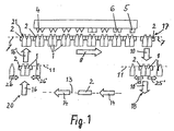
- bottles are sitting in packing carriers 2.
- various processing stations 4, 5, 6 are mounted, from left to right
- blowing nozzles for preheating then spray nozzles in the case of spraying a Sterilizing mixture as sterilizing medium, then various drying stations, a Cutting station, a filling station 6 and the sealing station 5, with the help of the filled bottles be closed.
- this closure may be which liquid food packaged sterile, by sealing a plastic-coated Aluminum foil done. It can be seen that all processing stations 4 and 6 are formed twice are, i. Two rows of bottles are always processed simultaneously, in the filling station 6, for example, filled, whereas the sealing station 5 with the relatively expensive sealing tools only simple or single-row is designed.
- the row of the pack carriers 2 under the processing stations 4 to 6 is in the first Process level 7, in which the package carrier 2 and thus the bottles 1 in the in FIG
- the first direction of travel shown arrow 8 are moved in Figure 1 so from left to right.
- FIG. 1 three dashed lines running parallel to one another which represent the represent first process plane 7, the second return plane 13 and the third loading plane 11.
- 17 is the above lying end between the horizontal working and along the first running direction in the first process plane 7 working first conveyor 19 and the second elevator conveyor 9.
- the below lying end 18 is the end of the second elevator 9 and the beginning of the third conveyor 12, which operates horizontally in the third direction 14.
- the latter ends in the lower one End 20 of the fourth elevator 15.
- the vertical and upward fourth elevator 15 finally creates the package carrier 2 again on the first process plane 7, namely on the overhead end 21 of the fourth elevator.
- the first conveyor 19 has the front end 21 and the rear end 17.
- the front end 21 is located above the lower end 20 of the fourth elevator 15, while the end 17 of the first conveyor 19 is above the lower end 18 of the second elevator 15. Be seen the ends 17 and 18 on the one hand and 21 and 20 on the other hand one above the other.
- the first conveyor 19 has a motor 22 as a separate drive.
- Both the lifting conveyor 9 and the lifting conveyor 15 each have a separate motor mounted in Figure 2 on the respective rear conveyor and therefore can not be seen. Their torque is transmitted via the drive shafts 23.
- the horizontal working third conveyor 12 in the second return plane 13 is also a separate Motor driven, think of the left lower and rear end in Figure 2 and therefore not shown. Its rotational force is transmitted via the drive shaft 24 to the horizontal conveyor lines 12 transmitted.
- the third loading plane 11 runs parallel to the first process plane 7, but also the Charging directions shown by the arrows 25, 25 'and 26, 26'.
- the means of loading and unloading are not shown in the drawings. But you can easily oscillate back and forth Introduce bar-mounted slides, with which a whole series of bottles at the same time for unloading in the directions 25 to the right and left and for loading in the direction 26 is moved from the right and from the left in the middle.
- the movement of the pack carrier 2 runs approximately as shown in FIGS. 1 and 2 such that most of the pack carriers 2 are located in the first process plane 7 and only one or two pack carriers are in the return, for example.
- the engine 22 ( Figure 2) drives via a gear 27 from the center to both sides towards each a shaft 28, so that on each side of a rocker arm 29 and a connecting rod 30 an oscillating hinund ago movement of a carriage 31 is generated to on each side of a push rod 32 to move in the first direction 8 and vice versa in the opposite direction.
- the intermittent movement of the individual pack carrier 2 by one Clock length concerned, especially in the movement from one processing station 4 to the next etc. up to the filling station 6. From there on, a two-stage movement takes place to the sealing station 5 towards, as will be described below.
- FIG. 3 shows the hygiene chamber 3, in the lower region of which the third conveyor 12 located.
- This moves just a pack carrier 2 to the left under the generally designated 40authenticnzu slaughter issued.
- This consists of two spaced apart tunnel-like spaces 41, in which bottle-shaped packs 1 are shown. These bottles are just by not shown pack passage openings against the line of sight Observers of Figure 3 in the hygiene room 3 has been promoted.
- the between the two tunnel-like Chambers 41 arranged pack carrier must first imagine empty. First after by computational sliding devices from retaining strips, not shown, the bottles 1 from the right and from the left have been inserted laterally into the pack carrier 2, are the bottles also supported on the package carrier 2, as shown in Figure 3. But then the bottles 1 would have to be taken out in the tunnel-like spaces 41.
- the Gas extraction devices are generally designated 42. They are above the tunnel-like Spaces 41 and extend in the direction of the viewer of Figure 3 from the front to the end behind to the 43 designated rear wall of the sanitary chamber 3. In this wall 43 are appropriately designed and sized holes through which the gases in the Space behind the sanitary chamber 3 and outside of the same can be sucked.
- a similar construction is also found below the downstream end of the upper process plane 7, namely on the bottle feeder 40 opposite side.
- Here's 44 in general referred to the bottle removal device. It consists of a similar way to the bottle feeder 40 from tunnel-like rooms, in which here the sterile filled and closed bottles 1 'are located. Above this, a gas suction device 42 is attached again.
- FIG 3 one has in the top wall 47 of the sanitary chamber 3, a plurality of openings as Intake 50 for sterilizing medium to think.
- the many white arrows show the entry of sterile Air from a source 51 for sterile air.
- the two dark arrows indicate the supply of sterilant from a source 52.
- Both the sterilant from source 52 and the sterile one Air from the source 51 in total so the (mixed) sterilization medium flows into the upper Room 48 of the hygiene chamber 3 (in Figure 3 perpendicular from top to bottom) and is characterized by the predominantly closed field 46 of the pack carrier 2 deflected so that it is substantially flows parallel to the conveying direction (first direction 8) of the pack carrier 2.
- an area 58 of medium concentration of the sterilizing medium of sterilizing agent develops next to and below the closed field 46 of the pack carrier 2.
- the region 59 of low concentration of the sterilizing medium of sterilizing agent develops.
- the different areas 56-59 are characterized by different degrees of gray coloration in FIG.
- the white ones Fields in the tunnel-like spaces 41 the lack of sterilant (areas of minimal concentration).
- Each pack carrier 2 has the shape in the preferred embodiment shown here an elongated, transversely to the first direction 8 extending bar and the shape of a Sheet. From the front 33 ( Figure 5) of the pack carrier 2 extending U-shaped, after outside to this side 33 out open recesses 35. Also from the diametrically opposite rear side 34 of the pack carrier 2 extends - but inversely to the recesses on the front 33 - a series of recesses 35 open to the rear in the case of the packs 1 here, bottles with a neck 36 arranged at their opening is the width B ( Figure 5) on the outer diameter D ( Figure 5) is adjusted so that the Bottle with her neck 36, for example, has external thread, drive into the recess 35 and can be held there.
- This holder is independent of the design of the bottle at the bottom, be it long, round, angular, short, tall or short.
- the second lifting conveyor 9 and the fourth elevator 15 work with vertically driven carriage 37, the on Both sides with the respective packing carriers 2 come into engagement and these from the first Lower process plane 7 into the second return plane 13 (lifting conveyor 9) or vice versa (lifting conveyor 15).
- the third, horizontal conveyor 12 works with an endless belt 38 with patch pockets 39, in which the package carrier 2 are inserted vertically.
- each push rod 32 are at intervals a ( Figure 2) feed cam 49 in a certain Angle of the push rod 32 mounted radially projecting. This distance a is equal to the center distance two adjacent to each other driven pack carrier 2. This allows the Push rods 32 are driven by oscillating unspecified locking grooves.
- the outer tunnel-like spaces 41 are empty, so that the pack carrier 2 by the above empty space from the loading level 11 are promoted upwards in the first process plane 7 where he can move according to trajectory 45 (black arrow, figure 4) on the horizontal conveyor is implemented.
- the package carrier 2 closes on the already existing strand of Pakkungschi on, so that the closed field 46 of the pack carrier 2 results, as in the figures 1-4 is illustrated.
- the bottle openings are now through the area 58 Medium Concentration has been moved to the 57 high concentration area and is now adding up their first running direction 8 (in Figures 1 to 4 from left to right) under the openings of the Inlet 50 for sterilizing medium.
- the package carrier 2 with the treated, sterile-filled and sealed bottles 1 becomes down to the third loading level 11 geföderf.
Landscapes
- Engineering & Computer Science (AREA)
- Mechanical Engineering (AREA)
- Filling Of Jars Or Cans And Processes For Cleaning And Sealing Jars (AREA)
- Basic Packing Technique (AREA)
- Apparatus For Disinfection Or Sterilisation (AREA)
- Supplying Of Containers To The Packaging Station (AREA)
- Food Preservation Except Freezing, Refrigeration, And Drying (AREA)
Claims (9)
- Dispositif de remplissage stérile d'emballages (1) en forme de bouteilles avec des produits alimentaires fluides, par exemple des boissons, dans lequel un dispositif de transport (19) entraíné par intermittence comporte des supports d'emballage, disposés en ligne les uns derrière les autres dans une première direction de déplacement (8) et passant par des stations de traitement (4, 5, 6), et est disposé dans une chambre d'hygiène (3) qui est dotée, à l'entrée (40) et à la sortie (44), d'ouvertures de passage d'emballages et d'au moins une entrée (50) destinée au fluide de stérilisation, de moyens (19, 27 à 32) destinés à déplacer de façon adjacente les supports d'emballage (2) au niveau du brin supérieur du dispositif de transport (19) de telle sorte que les supports d'emballage (2) forment dans un plan de traitement (7) une zone essentiellement fermée (46) qui est disposée à distance de la paroi supérieure (47) de la chambre d'hygiène (3) en formant un espace supérieur (48), d'une entrée (50) destinée au fluide de stérilisation qui est ménagée dans la paroi supérieure (47) de la chambre d'hygiène (3), de moyens d'injection du fluide de stérilisation avec une surpression dans l'espace supérieur (48) de la chambre d'hygiène (3), et de moyens d'amenée du fluide de stérilisation sensiblement parallèlement à une première direction de transport (8) des supports d'emballage (2),
caractérisé par
des moyens de chargement et déchargement des emballages (1) dans un plan de chargement (11) qui s'étend parallèlement au plan de traitement (7),
un autre transporteur (12) placé dans un plan de retour (13) avec une direction de déplacement (14) parallèle mais opposée à la première direction de déplacement (8) dans le plan de traitement (7),
des fentes aux extrémités de la zone de support fermée (46) dans la chambre d'hygiène (3) à côté de la surface frontale pour faire sortir le fluide de stérilisation de l'espace (48) et par les ouvertures de passage d'emballages conformées en sas dynamique, et
des dispositifs d'évacuation de gaz montés à côté des ouvertures de passage d'emballages et à l'extérieur de la chambre d'hygiène (3) et destinés à évacuer les gaz par aspiration vers l'extérieur de la chambre d'hygiène (3). - Dispositif selon la revendication 1, caractérisé en ce que l'entrée (50) destinée au fluide de stérilisation comporte un grand nombre d'ouvertures ménagées à distance les unes des autres dans la paroi supérieure (47) de la chambre d'hygiène (3).
- Dispositif selon la revendication 2, caractérisé en ce que les ouvertures sont reliées à des conduites d'amenée commandées par clapet.
- Dispositif selon l'une des revendications 1 à 3, caractérisé en ce que des stations de traitement (4, 5, 6) sont montées dans l'espace supérieur (48) de la chambre d'hygiène (3) sous sa paroi supérieure (47).
- Dispositif selon l'une des revendications 1 à 4, caractérisé en ce que chaque support d'emballage (2) a une structure sensiblement plane et est maintenu dans une position sensiblement horizontale par un circuit fermé de transport.
- Dispositif selon l'une des revendications 1 à 5, caractérisé en ce que le support d'emballage (2) comporte sur deux côtés diamétralement opposés (33, 34) des évidements (35) en forme de U qui sont ouverts vers l'extérieur et qui sont orientés parallèlement au premier sens de transport (8).
- Dispositif selon la revendication 6, caractérisé en ce que le support d'emballage (2) a la forme d'une baguette allongée s'étendant transversalement à la première direction de transport (8) de telle sorte que les évidements (35) viennent se placer par paire les uns à côté des autres.
- Dispositif selon l'une des revendications 1 à 7, caractérisé en ce que le support d'emballage (2) destiné à supporter des emballages (1) en forme de bouteille est une tôle en forme de baguette comportant des paires d'évidements (35) en forme de U qui sont opposés l'un à l'autre, lesdites paires étant disposées les unes à côté des autres transversalement au premier sens de transport (8) et la largeur (B) des évidements correspondant sensiblement au diamètre extérieur (D) du col (36) de l'emballage (1) en forme de bouteille.
- Dispositif selon l'une des revendications 1 à 8, caractérisé par des moyens d'amenée d'azote gazeux stérile dans l'emballage correspondant (1) de façon que l'azote remplisse à peu près tout le volume de l'emballage (1), de préférence avant de remplir l'emballage (1) avec le produit alimentaire liquide.
Applications Claiming Priority (3)
| Application Number | Priority Date | Filing Date | Title |
|---|---|---|---|
| DE10065591A DE10065591B4 (de) | 2000-12-28 | 2000-12-28 | Vorrichtung zum sterilen Befüllen von flaschenförmigen Packungen |
| DE10065591 | 2000-12-28 | ||
| PCT/EP2001/014745 WO2002053487A1 (fr) | 2000-12-28 | 2001-12-14 | Dispositif de remplissage aseptique d'emballages en forme de bouteilles |
Publications (2)
| Publication Number | Publication Date |
|---|---|
| EP1345839A1 EP1345839A1 (fr) | 2003-09-24 |
| EP1345839B1 true EP1345839B1 (fr) | 2005-04-06 |
Family
ID=7669350
Family Applications (1)
| Application Number | Title | Priority Date | Filing Date |
|---|---|---|---|
| EP01985403A Expired - Lifetime EP1345839B1 (fr) | 2000-12-28 | 2001-12-14 | Dispositif de remplissage aseptique d'emballages en forme de bouteilles |
Country Status (11)
| Country | Link |
|---|---|
| US (1) | US6820660B1 (fr) |
| EP (1) | EP1345839B1 (fr) |
| JP (1) | JP4100558B2 (fr) |
| CN (1) | CN1205110C (fr) |
| AT (1) | ATE292601T1 (fr) |
| BR (1) | BR0116602A (fr) |
| CA (1) | CA2430561C (fr) |
| DE (2) | DE10065591B4 (fr) |
| ES (1) | ES2236334T3 (fr) |
| MX (1) | MXPA03005765A (fr) |
| WO (1) | WO2002053487A1 (fr) |
Families Citing this family (15)
| Publication number | Priority date | Publication date | Assignee | Title |
|---|---|---|---|---|
| ATE342868T1 (de) * | 2001-12-14 | 2006-11-15 | Stork Food & Dairy Systems Bv | Abfüllvorrichtung mit ausrichtbarer begasungsvorrichtung |
| DE10326618A1 (de) * | 2003-06-13 | 2005-01-05 | Khs Maschinen- Und Anlagenbau Ag, Patentabteilung | Behälterbehandlungsmaschine |
| US7308919B1 (en) | 2004-10-18 | 2007-12-18 | Sergio Zavala | Refill apparatus for multiple containers |
| DE102006033264B4 (de) * | 2006-07-18 | 2008-07-31 | Venjakob Maschinenbau Gmbh & Co. Kg | Schalldämmende Fördervorrichtung |
| WO2008037326A2 (fr) * | 2006-09-26 | 2008-04-03 | CFS Bühl GmbH | Traitement sanitaire des aliments, chaîne de transport et d'emballage pour réaliser des produits allongés et pour déterminer la durée de stockage d'un produit |
| IT1391065B1 (it) * | 2008-10-17 | 2011-11-18 | Co Ri M A S R L | Macchina per il riempimento di fiale |
| DE102011007280A1 (de) | 2011-04-13 | 2012-10-18 | Krones Aktiengesellschaft | Behälterbehandlungsmaschine und Verfahren zur Behälterbehandlung |
| DE102011079077A1 (de) | 2011-07-13 | 2013-01-17 | Krones Aktiengesellschaft | Blasmaschine für Kunststoffbehälter |
| DE102011079076A1 (de) | 2011-07-13 | 2013-01-17 | Krones Aktiengesellschaft | Transportmittel für Behälter und Verfahren zum Transport von Behältern |
| DE102011079078A1 (de) | 2011-07-13 | 2013-01-17 | Krones Ag | Einsternzuführung für Behandlungsmaschinen |
| RU2696080C1 (ru) * | 2018-11-12 | 2019-07-30 | Евгений Федорович Клинецкий | Способ поддержания стерильной атмосферы в блоке розлива |
| RU2694248C1 (ru) * | 2018-12-13 | 2019-07-10 | Евгений Федорович Клинецкий | Установка для розлива напитков |
| JP2022552166A (ja) * | 2019-10-04 | 2022-12-15 | テトラ ラバル ホールディングス アンド ファイナンス エス エイ | 衛生チャンバを備えた充填機 |
| RU2740572C9 (ru) * | 2020-11-09 | 2021-05-28 | Евгений Федорович Клинецкий | Установка для розлива напитков |
| US11672901B2 (en) | 2021-06-04 | 2023-06-13 | ec2 Software Solutions, LLC | Radiopharmaceutical pig cleaning and transportation system |
Family Cites Families (14)
| Publication number | Priority date | Publication date | Assignee | Title |
|---|---|---|---|---|
| DE2214080C3 (de) | 1972-03-23 | 1975-11-13 | Hamba-Maschinenfabrik Hans A. Mueller, 5600 Wuppertal-Vohwinkel | Vorrichtung zum sterilen Abfüllen von Nahrungs- und Genußmitteln |
| US3783581A (en) * | 1972-04-18 | 1974-01-08 | Dart Ind Inc | Aseptic packaging method and machine |
| US4014158A (en) * | 1973-08-24 | 1977-03-29 | Ab Ziristor | Apparatus for filling and sealing preformed packaging containers under aseptic conditions |
| DE3522996A1 (de) * | 1985-06-27 | 1987-01-08 | Kolbus Gmbh & Co Kg | Verfahren zur abgrenzung steriler raeume gegen austreten von toxischen sterilisationsmitteln oder eindringen von mikroorganismen, vorzugsweise in anwendung fuer fuellmaschinen, und vorrichtung zur durchfuehrung des verfahrens |
| JPH0815902B2 (ja) * | 1987-12-28 | 1996-02-21 | 三菱重工業株式会社 | 無菌充填機 |
| DE3814650C1 (fr) * | 1988-04-29 | 1989-04-27 | Siegfried 8901 Koenigsbrunn De Ammann | |
| JP2690062B2 (ja) * | 1990-01-26 | 1997-12-10 | 雪印乳業株式会社 | 充填機における搬送装置 |
| JP2541918Y2 (ja) * | 1991-05-07 | 1997-07-23 | 四国化工機株式会社 | 容器搬送コンベヤ |
| JP2540276B2 (ja) * | 1993-03-12 | 1996-10-02 | 株式会社山東鉄工所 | 容器内部の殺菌装置 |
| DE19817735C1 (de) * | 1998-04-21 | 1999-11-11 | Fehland Engineering Gmbh | Getränkeabfüllvorrichtung |
| DE29923443U1 (de) | 1998-09-22 | 2000-09-14 | Sig Combibloc International Sy | Vorrichtung zum Entkeimen von Behältern in einer Füllmaschine |
| WO2000045862A1 (fr) | 1999-02-02 | 2000-08-10 | Steuben Foods, Inc. | Procede et appareil de conditionnement aseptique |
| US6209591B1 (en) * | 1999-02-02 | 2001-04-03 | Steuben Foods, Inc. | Apparatus and method for providing container filling in an aseptic processing apparatus |
| DE10008876A1 (de) * | 2000-02-25 | 2001-09-06 | Hamba Maschf | Vorrichtung zum Befüllen von Flaschen und anderen Behältern mit Nahrungs- und Genußmitteln, wie mit dünnflüssigen bis pasteusen Molkerei- und Fettprodukten, Säften, Wässern od. dgl. |
-
2000
- 2000-12-28 DE DE10065591A patent/DE10065591B4/de not_active Expired - Fee Related
-
2001
- 2001-12-14 CA CA002430561A patent/CA2430561C/fr not_active Expired - Fee Related
- 2001-12-14 ES ES01985403T patent/ES2236334T3/es not_active Expired - Lifetime
- 2001-12-14 JP JP2002554613A patent/JP4100558B2/ja not_active Expired - Fee Related
- 2001-12-14 BR BR0116602-6A patent/BR0116602A/pt not_active IP Right Cessation
- 2001-12-14 DE DE50105861T patent/DE50105861D1/de not_active Expired - Lifetime
- 2001-12-14 US US10/450,225 patent/US6820660B1/en not_active Expired - Fee Related
- 2001-12-14 EP EP01985403A patent/EP1345839B1/fr not_active Expired - Lifetime
- 2001-12-14 CN CNB018207766A patent/CN1205110C/zh not_active Expired - Fee Related
- 2001-12-14 MX MXPA03005765A patent/MXPA03005765A/es active IP Right Grant
- 2001-12-14 WO PCT/EP2001/014745 patent/WO2002053487A1/fr active IP Right Grant
- 2001-12-14 AT AT01985403T patent/ATE292601T1/de not_active IP Right Cessation
Also Published As
| Publication number | Publication date |
|---|---|
| WO2002053487A1 (fr) | 2002-07-11 |
| ATE292601T1 (de) | 2005-04-15 |
| DE10065591A1 (de) | 2002-09-19 |
| JP2004517008A (ja) | 2004-06-10 |
| JP4100558B2 (ja) | 2008-06-11 |
| ES2236334T3 (es) | 2005-07-16 |
| CN1205110C (zh) | 2005-06-08 |
| CA2430561C (fr) | 2007-08-21 |
| US6820660B1 (en) | 2004-11-23 |
| DE10065591B4 (de) | 2005-04-28 |
| CA2430561A1 (fr) | 2002-07-11 |
| CN1481333A (zh) | 2004-03-10 |
| DE50105861D1 (de) | 2005-05-12 |
| MXPA03005765A (es) | 2004-05-04 |
| BR0116602A (pt) | 2004-02-10 |
| EP1345839A1 (fr) | 2003-09-24 |
Similar Documents
| Publication | Publication Date | Title |
|---|---|---|
| EP0932577B1 (fr) | Procede et dispositif de sterilisation et de remplissage de conditionnements | |
| EP1345839B1 (fr) | Dispositif de remplissage aseptique d'emballages en forme de bouteilles | |
| EP3019405B1 (fr) | Dispositif et procédé de dépliage, de remplissage et de fermeture d'enveloppes d'emballage | |
| EP1268319B1 (fr) | Dispositif convoyeur equipe de supports de packs | |
| DE10008874C1 (de) | Vorrichtung zum Befüllen von Flaschen und anderen Behältern mit Nahrungs- und Genußmitteln, wie mit dünnflüssigen bis pasteusen Molkerei- und Fettprodukten, Säften, Wässern od. dgl. | |
| DE69915257T2 (de) | Einheit zum Sterilisieren eines Materialstreifens in einer Verpackungsmaschine für das Verpacken von fliessfähigen Nahrungsmitteln, und Verpackungsmaschine mit einer solchen Einheit | |
| DE102004026565B4 (de) | Verfahren zum Reinigen von Flaschen o.dgl. Behälter sowie Reinigungsmaschine | |
| DE602004007195T2 (de) | Verfahren zur Pasteurisation von Oberflächen | |
| DE102007003334A1 (de) | Verfahren und Vorrichtung zur kontinuierlichen Sterilisierung von Beutelverpackungen | |
| EP2421662A2 (fr) | Dispositif et procédé de conditionnement de produits dans des contenants | |
| DE60210148T2 (de) | Füllvorrichtung mit gehäuse mit einer zentralen gasabführung | |
| DE202018104454U1 (de) | Behandlungsvorrichtung für Behälter mit einem direkten Strom eines sterilen Gases | |
| DE4313325C2 (de) | Vorrichtung zum Füllen und Verschließen von Packungen | |
| EP3732107B1 (fr) | Dispositif d'emballage et procédé pour faire fonctionner ce dispositif d'emballage | |
| DE3701915A1 (de) | Verfahren und maschine zur sterilverpackung von fuellguetern in behaeltern | |
| DE10122032A1 (de) | Bandfördervorrichtung | |
| EP3587340B1 (fr) | Dispositif de manipulation des fermetures de récipients | |
| DE4037254C2 (fr) | ||
| WO2019081276A1 (fr) | Dispositif et procédé de remplissage et/ou traitement d'emballages dans un espace ferme par des parois latérales | |
| DE3931672A1 (de) | Becherfuellwerk fuer nahrungs- und genussmittel, insbesondere fuer molkereiprodukte | |
| DE102004032786A1 (de) | Verpackungsmaschine mit einer Entkeimungsvorrichtung | |
| EP0460380B1 (fr) | Procédé et dispositif pour la stérilisation complète d'éléments d'emballage empilés, spécialement des gobelets plastiques avec des rigidités de paroi différentes | |
| EP3732109A1 (fr) | Dispositif d'emballage et procédé permettant de faire fonctionner un dispositif d'emballage | |
| DE2164500A1 (de) | Maschine zum herstellen von mit fluessigen oder plastischen stoffen gefuellten sterilen packungen | |
| DE19855871A1 (de) | Verfahren und Vorrichtung in einer Füllmaschine |
Legal Events
| Date | Code | Title | Description |
|---|---|---|---|
| PUAI | Public reference made under article 153(3) epc to a published international application that has entered the european phase |
Free format text: ORIGINAL CODE: 0009012 |
|
| 17P | Request for examination filed |
Effective date: 20030521 |
|
| AK | Designated contracting states |
Kind code of ref document: A1 Designated state(s): AT BE CH CY DE DK ES FI FR GB GR IE IT LI LU MC NL PT SE TR |
|
| AX | Request for extension of the european patent |
Extension state: AL LT LV MK RO SI |
|
| 17Q | First examination report despatched |
Effective date: 20040212 |
|
| GRAP | Despatch of communication of intention to grant a patent |
Free format text: ORIGINAL CODE: EPIDOSNIGR1 |
|
| GRAS | Grant fee paid |
Free format text: ORIGINAL CODE: EPIDOSNIGR3 |
|
| GRAA | (expected) grant |
Free format text: ORIGINAL CODE: 0009210 |
|
| AK | Designated contracting states |
Kind code of ref document: B1 Designated state(s): AT BE CH CY DE DK ES FI FR GB GR IE IT LI LU MC NL PT SE TR |
|
| PG25 | Lapsed in a contracting state [announced via postgrant information from national office to epo] |
Ref country code: NL Free format text: LAPSE BECAUSE OF FAILURE TO SUBMIT A TRANSLATION OF THE DESCRIPTION OR TO PAY THE FEE WITHIN THE PRESCRIBED TIME-LIMIT Effective date: 20050406 Ref country code: FI Free format text: LAPSE BECAUSE OF FAILURE TO SUBMIT A TRANSLATION OF THE DESCRIPTION OR TO PAY THE FEE WITHIN THE PRESCRIBED TIME-LIMIT Effective date: 20050406 Ref country code: IE Free format text: LAPSE BECAUSE OF FAILURE TO SUBMIT A TRANSLATION OF THE DESCRIPTION OR TO PAY THE FEE WITHIN THE PRESCRIBED TIME-LIMIT Effective date: 20050406 Ref country code: GB Free format text: LAPSE BECAUSE OF FAILURE TO SUBMIT A TRANSLATION OF THE DESCRIPTION OR TO PAY THE FEE WITHIN THE PRESCRIBED TIME-LIMIT Effective date: 20050406 Ref country code: TR Free format text: LAPSE BECAUSE OF FAILURE TO SUBMIT A TRANSLATION OF THE DESCRIPTION OR TO PAY THE FEE WITHIN THE PRESCRIBED TIME-LIMIT Effective date: 20050406 |
|
| REG | Reference to a national code |
Ref country code: GB Ref legal event code: FG4D Free format text: NOT ENGLISH |
|
| REG | Reference to a national code |
Ref country code: CH Ref legal event code: EP |
|
| REG | Reference to a national code |
Ref country code: IE Ref legal event code: FG4D Free format text: LANGUAGE OF EP DOCUMENT: GERMAN |
|
| REF | Corresponds to: |
Ref document number: 50105861 Country of ref document: DE Date of ref document: 20050512 Kind code of ref document: P |
|
| PG25 | Lapsed in a contracting state [announced via postgrant information from national office to epo] |
Ref country code: SE Free format text: LAPSE BECAUSE OF FAILURE TO SUBMIT A TRANSLATION OF THE DESCRIPTION OR TO PAY THE FEE WITHIN THE PRESCRIBED TIME-LIMIT Effective date: 20050706 Ref country code: GR Free format text: LAPSE BECAUSE OF FAILURE TO SUBMIT A TRANSLATION OF THE DESCRIPTION OR TO PAY THE FEE WITHIN THE PRESCRIBED TIME-LIMIT Effective date: 20050706 Ref country code: DK Free format text: LAPSE BECAUSE OF FAILURE TO SUBMIT A TRANSLATION OF THE DESCRIPTION OR TO PAY THE FEE WITHIN THE PRESCRIBED TIME-LIMIT Effective date: 20050706 |
|
| REG | Reference to a national code |
Ref country code: ES Ref legal event code: FG2A Ref document number: 2236334 Country of ref document: ES Kind code of ref document: T3 |
|
| PG25 | Lapsed in a contracting state [announced via postgrant information from national office to epo] |
Ref country code: PT Free format text: LAPSE BECAUSE OF FAILURE TO SUBMIT A TRANSLATION OF THE DESCRIPTION OR TO PAY THE FEE WITHIN THE PRESCRIBED TIME-LIMIT Effective date: 20050908 |
|
| NLV1 | Nl: lapsed or annulled due to failure to fulfill the requirements of art. 29p and 29m of the patents act | ||
| GBV | Gb: ep patent (uk) treated as always having been void in accordance with gb section 77(7)/1977 [no translation filed] |
Effective date: 20050406 |
|
| REG | Reference to a national code |
Ref country code: IE Ref legal event code: FD4D |
|
| PG25 | Lapsed in a contracting state [announced via postgrant information from national office to epo] |
Ref country code: CY Free format text: LAPSE BECAUSE OF FAILURE TO SUBMIT A TRANSLATION OF THE DESCRIPTION OR TO PAY THE FEE WITHIN THE PRESCRIBED TIME-LIMIT Effective date: 20051214 Ref country code: AT Free format text: LAPSE BECAUSE OF NON-PAYMENT OF DUE FEES Effective date: 20051214 |
|
| PG25 | Lapsed in a contracting state [announced via postgrant information from national office to epo] |
Ref country code: BE Free format text: LAPSE BECAUSE OF NON-PAYMENT OF DUE FEES Effective date: 20051231 Ref country code: CH Free format text: LAPSE BECAUSE OF NON-PAYMENT OF DUE FEES Effective date: 20051231 Ref country code: LI Free format text: LAPSE BECAUSE OF NON-PAYMENT OF DUE FEES Effective date: 20051231 Ref country code: LU Free format text: LAPSE BECAUSE OF NON-PAYMENT OF DUE FEES Effective date: 20051231 Ref country code: MC Free format text: LAPSE BECAUSE OF NON-PAYMENT OF DUE FEES Effective date: 20051231 |
|
| PLBE | No opposition filed within time limit |
Free format text: ORIGINAL CODE: 0009261 |
|
| STAA | Information on the status of an ep patent application or granted ep patent |
Free format text: STATUS: NO OPPOSITION FILED WITHIN TIME LIMIT |
|
| 26N | No opposition filed |
Effective date: 20060110 |
|
| ET | Fr: translation filed | ||
| REG | Reference to a national code |
Ref country code: CH Ref legal event code: PL |
|
| BERE | Be: lapsed |
Owner name: TETRA LAVAL HOLDINGS & FINANCE SA Effective date: 20051231 |
|
| PGFP | Annual fee paid to national office [announced via postgrant information from national office to epo] |
Ref country code: ES Payment date: 20121205 Year of fee payment: 12 Ref country code: IT Payment date: 20121123 Year of fee payment: 12 |
|
| PGFP | Annual fee paid to national office [announced via postgrant information from national office to epo] |
Ref country code: DE Payment date: 20141121 Year of fee payment: 14 |
|
| PGFP | Annual fee paid to national office [announced via postgrant information from national office to epo] |
Ref country code: FR Payment date: 20141217 Year of fee payment: 14 |
|
| REG | Reference to a national code |
Ref country code: ES Ref legal event code: FD2A Effective date: 20150430 |
|
| PG25 | Lapsed in a contracting state [announced via postgrant information from national office to epo] |
Ref country code: ES Free format text: LAPSE BECAUSE OF NON-PAYMENT OF DUE FEES Effective date: 20131215 |
|
| PG25 | Lapsed in a contracting state [announced via postgrant information from national office to epo] |
Ref country code: IT Free format text: LAPSE BECAUSE OF NON-PAYMENT OF DUE FEES Effective date: 20131231 |
|
| PG25 | Lapsed in a contracting state [announced via postgrant information from national office to epo] |
Ref country code: IT Free format text: LAPSE BECAUSE OF NON-PAYMENT OF DUE FEES Effective date: 20131214 |
|
| REG | Reference to a national code |
Ref country code: DE Ref legal event code: R119 Ref document number: 50105861 Country of ref document: DE |
|
| REG | Reference to a national code |
Ref country code: FR Ref legal event code: ST Effective date: 20160831 |
|
| PG25 | Lapsed in a contracting state [announced via postgrant information from national office to epo] |
Ref country code: DE Free format text: LAPSE BECAUSE OF NON-PAYMENT OF DUE FEES Effective date: 20160701 |
|
| PG25 | Lapsed in a contracting state [announced via postgrant information from national office to epo] |
Ref country code: FR Free format text: LAPSE BECAUSE OF NON-PAYMENT OF DUE FEES Effective date: 20151231 |