EP1344817A1 - Apparatus for microscopic observation of long-term culture of single cell - Google Patents
Apparatus for microscopic observation of long-term culture of single cell Download PDFInfo
- Publication number
- EP1344817A1 EP1344817A1 EP01997537A EP01997537A EP1344817A1 EP 1344817 A1 EP1344817 A1 EP 1344817A1 EP 01997537 A EP01997537 A EP 01997537A EP 01997537 A EP01997537 A EP 01997537A EP 1344817 A1 EP1344817 A1 EP 1344817A1
- Authority
- EP
- European Patent Office
- Prior art keywords
- cell
- culture
- long
- microscopic observation
- region
- Prior art date
- Legal status (The legal status is an assumption and is not a legal conclusion. Google has not performed a legal analysis and makes no representation as to the accuracy of the status listed.)
- Withdrawn
Links
Images










Classifications
-
- C—CHEMISTRY; METALLURGY
- C12—BIOCHEMISTRY; BEER; SPIRITS; WINE; VINEGAR; MICROBIOLOGY; ENZYMOLOGY; MUTATION OR GENETIC ENGINEERING
- C12M—APPARATUS FOR ENZYMOLOGY OR MICROBIOLOGY; APPARATUS FOR CULTURING MICROORGANISMS FOR PRODUCING BIOMASS, FOR GROWING CELLS OR FOR OBTAINING FERMENTATION OR METABOLIC PRODUCTS, i.e. BIOREACTORS OR FERMENTERS
- C12M25/00—Means for supporting, enclosing or fixing the microorganisms, e.g. immunocoatings
- C12M25/02—Membranes; Filters
-
- C—CHEMISTRY; METALLURGY
- C12—BIOCHEMISTRY; BEER; SPIRITS; WINE; VINEGAR; MICROBIOLOGY; ENZYMOLOGY; MUTATION OR GENETIC ENGINEERING
- C12M—APPARATUS FOR ENZYMOLOGY OR MICROBIOLOGY; APPARATUS FOR CULTURING MICROORGANISMS FOR PRODUCING BIOMASS, FOR GROWING CELLS OR FOR OBTAINING FERMENTATION OR METABOLIC PRODUCTS, i.e. BIOREACTORS OR FERMENTERS
- C12M1/00—Apparatus for enzymology or microbiology
- C12M1/34—Measuring or testing with condition measuring or sensing means, e.g. colony counters
-
- C—CHEMISTRY; METALLURGY
- C12—BIOCHEMISTRY; BEER; SPIRITS; WINE; VINEGAR; MICROBIOLOGY; ENZYMOLOGY; MUTATION OR GENETIC ENGINEERING
- C12M—APPARATUS FOR ENZYMOLOGY OR MICROBIOLOGY; APPARATUS FOR CULTURING MICROORGANISMS FOR PRODUCING BIOMASS, FOR GROWING CELLS OR FOR OBTAINING FERMENTATION OR METABOLIC PRODUCTS, i.e. BIOREACTORS OR FERMENTERS
- C12M25/00—Means for supporting, enclosing or fixing the microorganisms, e.g. immunocoatings
-
- C—CHEMISTRY; METALLURGY
- C12—BIOCHEMISTRY; BEER; SPIRITS; WINE; VINEGAR; MICROBIOLOGY; ENZYMOLOGY; MUTATION OR GENETIC ENGINEERING
- C12M—APPARATUS FOR ENZYMOLOGY OR MICROBIOLOGY; APPARATUS FOR CULTURING MICROORGANISMS FOR PRODUCING BIOMASS, FOR GROWING CELLS OR FOR OBTAINING FERMENTATION OR METABOLIC PRODUCTS, i.e. BIOREACTORS OR FERMENTERS
- C12M41/00—Means for regulation, monitoring, measurement or control, e.g. flow regulation
- C12M41/30—Means for regulation, monitoring, measurement or control, e.g. flow regulation of concentration
- C12M41/36—Means for regulation, monitoring, measurement or control, e.g. flow regulation of concentration of biomass, e.g. colony counters or by turbidity measurements
-
- C—CHEMISTRY; METALLURGY
- C12—BIOCHEMISTRY; BEER; SPIRITS; WINE; VINEGAR; MICROBIOLOGY; ENZYMOLOGY; MUTATION OR GENETIC ENGINEERING
- C12M—APPARATUS FOR ENZYMOLOGY OR MICROBIOLOGY; APPARATUS FOR CULTURING MICROORGANISMS FOR PRODUCING BIOMASS, FOR GROWING CELLS OR FOR OBTAINING FERMENTATION OR METABOLIC PRODUCTS, i.e. BIOREACTORS OR FERMENTERS
- C12M41/00—Means for regulation, monitoring, measurement or control, e.g. flow regulation
- C12M41/46—Means for regulation, monitoring, measurement or control, e.g. flow regulation of cellular or enzymatic activity or functionality, e.g. cell viability
-
- G—PHYSICS
- G02—OPTICS
- G02B—OPTICAL ELEMENTS, SYSTEMS OR APPARATUS
- G02B21/00—Microscopes
- G02B21/34—Microscope slides, e.g. mounting specimens on microscope slides
-
- B—PERFORMING OPERATIONS; TRANSPORTING
- B01—PHYSICAL OR CHEMICAL PROCESSES OR APPARATUS IN GENERAL
- B01L—CHEMICAL OR PHYSICAL LABORATORY APPARATUS FOR GENERAL USE
- B01L3/00—Containers or dishes for laboratory use, e.g. laboratory glassware; Droppers
- B01L3/50—Containers for the purpose of retaining a material to be analysed, e.g. test tubes
- B01L3/502—Containers for the purpose of retaining a material to be analysed, e.g. test tubes with fluid transport, e.g. in multi-compartment structures
-
- G—PHYSICS
- G01—MEASURING; TESTING
- G01N—INVESTIGATING OR ANALYSING MATERIALS BY DETERMINING THEIR CHEMICAL OR PHYSICAL PROPERTIES
- G01N35/00—Automatic analysis not limited to methods or materials provided for in any single one of groups G01N1/00 - G01N33/00; Handling materials therefor
- G01N35/02—Automatic analysis not limited to methods or materials provided for in any single one of groups G01N1/00 - G01N33/00; Handling materials therefor using a plurality of sample containers moved by a conveyor system past one or more treatment or analysis stations
- G01N35/028—Automatic analysis not limited to methods or materials provided for in any single one of groups G01N1/00 - G01N33/00; Handling materials therefor using a plurality of sample containers moved by a conveyor system past one or more treatment or analysis stations having reaction cells in the form of microtitration plates
-
- G—PHYSICS
- G01—MEASURING; TESTING
- G01N—INVESTIGATING OR ANALYSING MATERIALS BY DETERMINING THEIR CHEMICAL OR PHYSICAL PROPERTIES
- G01N35/00—Automatic analysis not limited to methods or materials provided for in any single one of groups G01N1/00 - G01N33/00; Handling materials therefor
- G01N35/10—Devices for transferring samples or any liquids to, in, or from, the analysis apparatus, e.g. suction devices, injection devices
- G01N35/1002—Reagent dispensers
Definitions
- the invention of the present application relates to an apparatus for the microscopic observation of long-term culture of a single cell. More specifically, the invention relates to an apparatus for microscopic observation of long-term culture of a cell, which enables the culturing of cells in units of one cell while observing the state of a particular cell microscopically, in the field of biotechnology that use microorganisms and cells, as well as to a method of observation using such an apparatus.
- a circulation pump operates to raise the level of the culture medium above the top edge of the substrate, or lower the level of the culture medium below the bottom edge of the substrate, and maintains a constant nutritional state by supplying fresh culture medium when the level of the culture medium is low and discharging the culture medium when the level of the culture medium is high.
- JP-A-8-172956 discloses a structure consisting of a culture container into which an insertion tube for introducing fresh culture medium into a culture container, an extraction tube for discharging culture medium from the culture container, and a gas tube which connects the gas phase of the culture container and the pump, each comprising a filter for preventing bacteria from entering the culture container, are inserted, which can maintain the nutritional state of the culture container to a constant level.
- the subject of the present invention is to solve the above-described problems of the prior arts, and to provide a novel technical means for enabling: the culture of a cell group originating from a particular single cell; the culture and observation of cells while identifying cells that interact with them; and the observation of the difference between a cell to which a substance that interacts with the cells, such as a signal substance, has been added, and other cells.
- the invention also aims to provide novel means which enables the collection of a cell that assumes a particular state and the analysis or biochemical measurement of a gene or an expression mRNA of the cell.
- the present invention provides an apparatus for the microscopic observation of long-term culture of a single cell, which comprises: a cell culture container comprising a cell culture region consisting of a hole created on a substrate, a semi-permeable membrane covering the cell culture region and a culture medium exchange region on top of the semi-permeable membrane; a means for supplying liquid medium to the cell culture container; and an optical microscopic means for long-term microscopic observation of a cell within the cell culture region.
- a small culture container is set on the optical path of a microscopic observation system; the interior of the container comprises a cell culture region made of a small hole for culturing a cell, an optically transparent semi-permeable membrane that is coarse enough to prevent cells from passing through, which covers the top of the cell culture region to prevent the cell from coming out of the hole, and culture medium exchange region that allows the culture medium to circulate on the top of the semi-permeable membrane.
- the cell culture region includes one or a plurality of small holes each having a width of approximately several ⁇ m to several hundred ⁇ m, and the apparatus has a means for guiding a particular cell to the hole.
- the apparatus also has a means for supplying nutrition and oxygen required for the growth of the cell in the cell culture region to the cell from the solution exchanging region by diffusion from the solution circulation part, which also enables excrements or secretion to be eliminated; it also has a means for optically observing the cell.
- the apparatus has a means for controlling the number and type of cells in each hole of the cell culture region by a non-contact trapping technique such as optical tweezers and a carrying passage formed between each hole.
- the apparatus of the invention also has a means for controlling the solution temperature inside the container by temperate control means such as a Peltier element.
- temperate control means such as a Peltier element.
- the feed tube for feeding culture medium from a culture medium reservoir to the solution exchanging region has a degassing means, such as a degassing cell or a gas replacement cell, as well as a means for controlling the type and density of gas dissolved in the culture medium.
- the apparatus of the present invention has a means for guiding the tip of a pipet or the like to the top of a particular hole and spraying a drug or the like to exert the influence of the drug on a single cell in the particular hole via the semi-permeable membrane, and a means for extracting one particular cell from a particular hole through the semi-permeable membrane by means of a pipet or the like, as well as a means for introducing a filler or the like into a particular hole by means of a similar pipet or the like.
- one (single) cell provided in the invention of this application must not be construed as limiting the number of cells to be handled at a time to only one cell.
- a plurality of cells may be cultured in a hole of a cell culture region, and a feature of the invention of this application resides in the fact that even during the culture of a plurality of cells, it is possible to control and observe the culture process and the like of culture of a single particular cell.
- the term “one (single) cell” means that fact.
- the invention of this application is based on the above-described premises.
- Fig. 1 shows an example of the basic construction of an apparatus for microscopic observation of long-term culture.
- the apparatus for microscopic observation of long-term culture according to the invention of this application is provided with a culture container 105 constructed to culture a microorganism or a cell and to enable replacement of its culture medium.
- the apparatus is also provided with a culture medium supplying and draining system which provides a culture medium while adjusting the composition and the temperature of a culture medium to be sent into this culture container 105, the kind and the density of gas and atmosphere, and the like, and an microscopic observation optical system for observing a cell in the culture container 105 with the lapse of time and recording the observed result on video or in a personal computer or the like.
- the culture container 105 in which to culture a cell is provided with a gas discharging valve 104 for discharging gases such as air remaining in the container, whereby the culture container 105 is structured to be filled with a culture medium.
- the size of the bottom of the culture container 105 is made a size suitable for microscopic observation.
- this culture container 105 is placed on a stage 107.
- the culture medium supplied from a culture medium supplying device 12 having the function of supplying a plurality of kinds of culture media or culture media having different densities to the culture container 105 is first adjusted in solution temperature by a heater 122, and is guided to a dissolved gas replacement device 123 via a tube and dissolved gas components such as air are adjusted by the dissolved gas replacement device 123. Then, the culture medium is adjusted in flow rate by a pump 124, and is sent to the culture container 105 via a tube 125.
- the culture container 105 is provided with another tube 126, and the solution inside the culture container 105 passes through the tube 126 and is sent to a waste solution reservoir 128 by suction with a pump 127.
- the pump 124 and the pump 127 during observation, performs supply and drain of the culture medium of the culture container 105 at the same flow rate, but when the gas discharging valve 104 is in a closed state, either one of the pump 124 and the pump 127 can be omitted.
- the waste solution reservoir 128 is fitted with a heater so that the temperature of the culture medium can be adjusted, and by sending air or the like to a culture medium reservoir through a tube by a pump, it is also possible to bring the air contained in the culture medium into a saturated state.
- the culture medium reservoir may be connected to the waste solution reservoir 128 via the tube so that a valve can be opened and closed to circulate the culture medium to a supplying device such as a culture medium supplying device 121.
- a filter may also be disposed in the tube at a halfway position thereof so that extra components can be removed from a waste solution.
- the optical system with the basic construction shown in Fig. 1 is capable of illuminating a sample in two opposite directions, both from above and below.
- Light emitted from an upper light source 101 is adjusted to a particular wavelength by a filter 102, and is condensed by a condenser lens 103 and irradiated onto the culture container 105.
- the irradiated light is used as transmitted light for observation with an objective lens 131.
- a transmitted light image of the interior of the culture container 105 is guided to a camera 115 by a mirror 113 and forms an image on the photosensitive surface of the camera.
- the material of the culture container 105 and the material of a cell culture region substrate 106 for actually culturing a cell at the bottom of the culture container is desirably an optically transparent material.
- glass such as borosilicate glass or quartz glass, resins or plastics such as polystyrene, or a solid substrate such as a silicon substrate is used.
- light of wavelength 900 nm or more is used for observation.
- Light irradiated from a lower light source 110 is guided to the objective lens 131 by a dichroic mirror 112 after having been wavelength-selected. The light is used as excitation light for observation of fluorescence in the interior of the culture container 105.
- Fluorescent light emitted from the culture container 105 is again observed with the objective lens 131, and only fluorescent light and transmitted light from which the excitation light has been cut by a filter 114 can be observed with the camera 115.
- a mechanism is also provided which introduces laser light generated by a laser light source 108 into the objective lens 131 through a movable dichroic mirror 109.
- the focus position of the laser in the culture container 105 can be moved by moving the movable dichroic mirror.
- Image data obtained by the camera is analyzed by an image processing and analyzing device 116, and on the basis of various other analysis results such as the measured result of the temperature of a temperature measuring instrument attached to the culture container 105, it is possible to drive the movable dichroic mirror 109 as well as a stage moving motor 132 which causes the stage to move freely in the X-Y-Z directions in order to control the position of the stage having a temperature control function, on which the culture container 105 is placed.
- the shape of a cell can be recognized, and after recognition, the cell can be tracked and invariably positioned in the center of the image, or the image can be focused onto a particular cell by adjusting the distance to the objective lens.
- the movable dichroic mirror 109 and the stage 107 having a temperature control function, on which the culture container 105 is placed can be controlled at a predetermined period, and the stage moving motor 132 can be driven at predetermined intervals.
- Fig. 2 shows the arrangement of the culture container shown in Fig. 1.
- Figs. 3 and 5 show an A-A cross section of Fig. 2.
- the culture container 202 shown in Fig. 2 is, similarly to the above-described container, provided with a gas discharging valve 201, a tube 203 for supplying a culture medium, and a tube 204 for discharging a waste solution, and a cell culture region substrate 205 similar to the cell culture region substrate 106 shown in Fig. 1 is provided at the bottom of the culture container 202.
- the culture container 202 may be made of, for example, glass, but it is also possible to use various kinds of optically transparent containers made of a resin such as polypropylene or polystyrene, instead of glass.
- FIG. 3 shows a culture container for cell culture according to the invention of this application as well as a construction with which this culture container is provided.
- the culture medium supplied from the culture medium supplying device 121 shown in Fig. 1 described above is stored into a solution exchanging region 301A of a culture container 301 via the tube 302 shown in Fig. 3. Then, the fresh culture medium stored in this solution exchanging region 301A is replaced with an old culture medium inside cell culture regions 306 via a semi-permeable membrane 304.
- the cell culture regions 306 are made of a plurality of holes provided in a substrate 305. These holes are sealed at their tops by the semi-permeable membrane 304. Accordingly, the structure of the cell culture regions 306 is such that the cells sealed in the holes 306 cannot come out of these holes and unwanted microorganisms such as bacteria are prevented from entering from a culture medium part.
- each of these holes needs to be larger than the size of one cell. Accordingly, in general, in the case where a cell is to be cultured, the size of each of the holes, although depending on the size of the cell, can be made, for example, 3 mm or less in opening diameter and 300 ⁇ m in depth. More preferably, in order to advantageously achieve the expected object of the invention of this application, the opening diameter is set to from 1 ⁇ m to 1 mm, far more preferably, from 10 ⁇ m to 50 ⁇ m, and the depth is set to 100 ⁇ m or less. These opening diameter and depth may be appropriately adjusted according to the size and kind of cell to be cultured.
- h be larger than the depth of the holes, in view of the diffusion of the culture medium.
- the thickness of the cell culture region substrate it is necessary to use a thick substrate because an objective lens of high numerical aperture is used in the case where microscopic observation and optical trapping are performed with a 100-power objective lens.
- an objective lens of high numerical aperture is used in the case where microscopic observation and optical trapping are performed with a 100-power objective lens.
- a substrate made of borosilicate glass it is necessary to use a substrate of thickness 0.3 mm or less.
- the holes that constitute the cell culture regions 306 may be formed as a plurality of holes as described above, and in these holes, objective cells are cultured.
- a waste solution of the culture medium is drawn from the solution exchanging region 301A through a tube 303. Since the holes of the cell culture regions 306 are very shallow, the replacement of the culture medium is rapidly performed, and the old culture medium is discharged through the tube 303.
- the semi-permeable membrane 304 has micropores each having a size through which a cell cannot pass and an outside bacterium or the like cannot enter.
- the semi-permeable membrane 304 be 10,000 or more in molecular weight MW, 0.2 ⁇ m or less in pore size, and optically transparent.
- the semi-permeable membrane 304 Since the semi-permeable membrane 304, as described above, has a pore size through which a cell cannot pass, unwanted microorganisms do not enter from the solution exchanging region 301A of the culture container 301 or cells do not flow into the solution exchanging region 301A from the holes of the cell culture regions 306.
- the substrate 305 and the culture container 301 are made to adhere to each other by an adhesive seal 307 such as a silicone seal, whereby the culture medium is prevented from leaking from the solution exchanging region 301A.
- the substrate 305 is sealed by the semi-permeable membrane 304 with no clearance formed therebetween, except the tops of the holes of the cell culture regions 306. The reason for this is to disable a cell to move between one and another of the holes in the case where the cell culture regions 306 are made of a plurality of holes.
- a method using a bond between avidin and biotin is effective.
- Fig. 4 is a schematic cross-sectional view showing this bond.
- the -OH group of the semi-permeable membrane 401 is partly converted to a -CHO group, and this is -(CO) -NH-bonded to biotin modified with an amino group.
- the surface of the semi-permeable membrane 401 is modified with biotin 404.
- the surface of the glass substrate 402 is modified with an amino group by a silane coupling agent, and after that, the amino group is made to react with biotin having a -CHO group, whereby the surface of the substrate 402 can be modified with biotin similarly to the semi-permeable membrane.
- avidin 403 is added to cause the semi-permeable membrane 401 to adhere to the cell culture region substrate 402 with a biotin-avidin bond.
- the biotin (404) disposed by bonding on the surface of one of the semi-permeable membrane 401 and the substrate 402 is bonded to the biotin (404) disposed by bonding on the surface of the other via the avidin 403, whereby a superior seal effect can be realized.
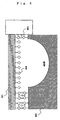
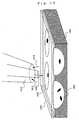
- Fig. 5 is a schematic view showing the status of culture of cells 503 in the holes of cell culture regions 502 provided in a substrate 501.
- the cells 503 in the holes of the cell culture regions 502 can be observed with a phase contrast microscope, a differential interference microscope or a fluorescence microscope similarly to the case of ordinary preparations.
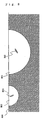
- Fig. 5 is a schematic view showing the status of culture of cells 803 and 805 in the holes of cell culture regions 802 and 804 having different sizes.
- the number of cells in each of the holes is one, but the holes differ from each other in cell density which is obtained by dividing the number of cells in a hole by the volume of the hole. In this manner, by controlling the volume of each hole, it is possible to observe various reactions of the same number of cells for different densities.
- the size (diameter) of a hole of a cell culture region by changing the size (diameter) of a hole of a cell culture region, it is possible to change the extent of the mean free path of a cell which is an objective target, or by changing the number of objective target cells to be placed into holes of the same size (diameter), it is possible to change the cell density of each of the holes.
- the shape of a hole for cell culture is changed, it is possible to observe the influence and effect of the shape on a cell.
- a plurality of holes serving as cell culture regions 902 and grooves 903 interconnecting these holes and serving as thin passages each of which allows one cell to narrowly pass therethrough may be provided on the surface of a substrate 901.
- the grooves 903 serving as such passages it is possible to measure, for example, the moving velocity, runnability and the like of cells.
- particle trapping means such as optical tweezers.
- optical tweezers it is possible to isolate or select cells, and it is possible to cause particular cells to interact with one another in a hole, as well as it is possible to control the number of cells in a hole.
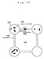
- Fig. 10 is a schematic plan view showing the manipulation of such cell movement.
- Holes serving as cell culture regions 1002 and grooves 1003 serving as passages for interconnecting these holes are provided in a substrate 1001, and a cell 1004 can be moved through the groove 1003 from a hole A to another hole B of the cell culture regions 1002 by optical tweezers 1005 means.
- the optical tweezers 1005 means in this case is means which has heretofore been well known, and is means for irradiating a target cell with a beam of laser light to trap the cell and enabling the cell to be moved in its trapped state with the movement of the beam of laser light.
- a particular cell can be carried from the hole of the cell reservoir 1104 to the hole of the cell culture region 1102 by the optical tweezers, and conversely, a particular cell can also be transferred or discarded into the hole of the cell reservoir 1104.
- a single-cell purification culture system can also be assembled on a cell culture region substrate 1201.
- cells are introduced into a sample introducing part 1202, and one of these cells is moved along a groove by the use of trapping means such as optical tweezers, and is guided to a cell culturing hole 1204.
- a cell trapping hole 1203 is disposed in this groove at a halfway position thereof to prevent a cell from swimming from 1202 into a hole 1204.
- one cell which is in a particular state is again taken out of a cell group cultured and grown from the one cell in the hole 1204, and this cell is similarly moved by the use of the trapping means, and is guided to a second culturing hole 1206.
- a cell trapping hole 1205 is disposed at a halfway position.
- Fig. 13 shows one example of a culture container different from the embodiment shown in Fig. 2.
- a pipet 1307 is introduced from the outside, and is inserted through a semi-permeable membrane 1304 to selectively collect cells in a hole 1306.
- a culture container 1301 is made open at its top, and a mineral oil 1312 is applied to cover the top surface of a culture medium 1313 with which the container is filled, thereby preventing the penetration of unwanted microorganisms.
- the amount of the culture medium to be introduced through a tube 1302 in the direction of an arrow 1311 is made smaller than the amount of solution to be sucked in the direction of an arrow 1317, and by the use of a solution level regulating part 1315, when this solution level becomes lower than a solution outlet 1316, air is sucked to stop the suction of solution, and when the solution level becomes higher to close the outlet 1316, the culture medium is again sucked, so that the solution level is held at a constant height.
- the solution level regulating part is installed separately from the culture container 105 so that ripples on a solution surface do not influence optical observation.
- the pipet 1307 can be used for sucking a cell, but can also be used for injecting a filler to close a particular hole or groove or for introducing a particular cell into a cell culture region through a semi-permeable membrane.
- the pipet 1307 can be used in the case of introducing a particular sample into the sample introducing part 1202 of the single-cell purification culture system shown in Fig. 12.
- since cells which assume a particular state can be collected in units of one cell with a pipet 1, gene polymorphism analysis, mRNA expression analysis and the like can be also performed on this one cell.
- Fig. 14 shows an embodiment in which a reagent for causing induction or the like is introduced into a cell in a particular hole 1402.
- a pipet has a double structure, and discharges a solution through an inside pipet 1411 and sucks a solution through an outside pipet 1412.
- the structure of the pipet is such that the solution discharged from the inside pipet 1411 is distributed in the vicinity of only its outlet and is prevented from leaking outwardly from the outside pipet 1412, by suction from the outside pipet 1412. Accordingly, this pipet can be brought to the vicinity of a particular hole and apply an action to only a particular cell.
- the cell trapping and moving means is not limited to the above-described optical tweezers, and may also be, for example, means using ultrasonic waves or means using electric fields.
- Fig. 15 shows one embodiment in which a plurality of. electrodes 1501, 1505 and 1508 are introduced in a cell culture region substrate 1501. Since a cell has a peculiar charge in a solution according to the state of the surface thereof, when a positive charge is applied to an electrode 1502, a cell 1511 having the opposite charge can be attracted to a hole 1503. By using this technique, cells corresponding to different strengths of negative charges are gathered in the hole 1503 and holes 1506 and 1509, respectively. In addition, if negative charges are applied to the electrodes 1505 and 1508, cells cannot move between each of the holes.
- Fig. 16 shows one example in which electrodes 1602 and 1603 are disposed on a cell culture region substrate 1601 and ultrasonic vibrators 1604 and 1605 are disposed.
- an electric field 1611 and an ultrasonic radiation pressure 1612 are used as non-contact forces for manipulating a cell.
- the electric field applies to a cell an external force corresponding to the surface charge of the cell, while the ultrasonic radiation pressure exerts over the cell an external force corresponding to the size and hardness of the cell.
- the frequency of an ultrasonic wave to be used at this time be made a frequency of 1 MHz or more so that the generation of bubbles (cavitation) can be restrained.
- the ultrasonic radiation pressure and the electric field are respectively made to act in different directions perpendicular to each other, whereby cell distribution corresponding to the charge and size of each cell can be two-dimensionally developed.
- an external force due to an electric field and an external force due to an ultrasonic wave are combined on one substrate to perform separation according to the kinds of cells, but external forces due to an electric field and an ultrasonic wave may also be independently used to transport a cell. Accordingly, it is possible to achieve cell handling similar to that used with optical tweezers.
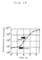
- Fig. 17 By using the above-described apparatus of this application, as shown in Fig. 17 by way of example, in an observation of E. coli growth, it has been confirmed that there is no difference in growth speed and division length between each generation and one E. coli bacterium divides into two when reaching a two-fold length. On the other hand, as shown in Fig. 18, it has been confirmed that growth depends on the size, i.e., the volume, of a hole of a cell culture region. In Fig. 18, "larger” indicates 2 ⁇ 10 -7 ml, and “small” indicates 2 ⁇ 10 -9 ml.
- This feature can be realized exclusively by the apparatus and the method according to the invention of this application which enables long-term culture and microscopic observation at the level of a single cell.
- novel technical means which makes it possible to culture a cell group originating from a particular single cell, to perform culture and observation while identifying cells to be subjected to interaction during the process of culturing cells, to spray a substance which interacts with cells, for example, a drug such as a signal substance, onto only a particular cell in a cell group which is being cultured so that cells are cultured at a constant cell density, and observe a difference in variation between the particular cell and other cells.
- novel means which makes it possible to collect only a cell assuming a particular state and perform analysis or biochemical measurement of a gene of the cell, an expressed mRNA and the like.
Landscapes
- Chemical & Material Sciences (AREA)
- Health & Medical Sciences (AREA)
- Life Sciences & Earth Sciences (AREA)
- Engineering & Computer Science (AREA)
- Bioinformatics & Cheminformatics (AREA)
- Wood Science & Technology (AREA)
- Organic Chemistry (AREA)
- Zoology (AREA)
- Biotechnology (AREA)
- Sustainable Development (AREA)
- Biomedical Technology (AREA)
- Microbiology (AREA)
- Biochemistry (AREA)
- General Engineering & Computer Science (AREA)
- General Health & Medical Sciences (AREA)
- Genetics & Genomics (AREA)
- Analytical Chemistry (AREA)
- Physics & Mathematics (AREA)
- Immunology (AREA)
- General Physics & Mathematics (AREA)
- Optics & Photonics (AREA)
- Cell Biology (AREA)
- Medicinal Chemistry (AREA)
- Apparatus Associated With Microorganisms And Enzymes (AREA)
Abstract
Novel technical means is provided with a cell culture
container having a cell culture region made of a hole formed
on a substrate, a semi-permeable membrane covering a top plane
of the cell culture region and a culture medium replacement
part provided over the semi-permeable membrane, means for
supplying a cell culture medium into the cell culture
container, and microscopic optical means for enabling
long-term observation of the cell within the cell culture
region. The novel technical means makes it possible to
culture a cell group originating from a particular single cell,
to perform culture and observation while identifying cells
to be subjected to interaction during the process of culturing
cells, to spray a substance which interacts with cells, for
example, a drug such as a signal substance, onto only a
particular cell in a cell group which is being cultured so
that cells are cultured at a constant cell density, and
observe a difference in variation between the particular cell
and other cells. There is also provided novel means which
makes it possible to collect only a cell assuming a particular
state and perform analysis or biochemical measurement of a
gene of the cell, an expressed mRNA and the like.
Description
The invention of the present application relates to an
apparatus for the microscopic observation of long-term
culture of a single cell. More specifically, the invention
relates to an apparatus for microscopic observation of
long-term culture of a cell, which enables the culturing of
cells in units of one cell while observing the state of a
particular cell microscopically, in the field of
biotechnology that use microorganisms and cells, as well as
to a method of observation using such an apparatus.
Conventionally, in the fields of biology, medicine and
pharmacy, changes in the state of a cell and the response of
a cell to a certain drug has been observed on the assumption
that the average value of a cell cluster represent the
characteristic of one cell. However, in reality, cell cycles
rarely synchronize with one another in a cell cluster and each
of the cells expresses protein at a different cycle. Although
synchronous culture methods have been developed in order to
solve such problems, because the cultured cells do not
originate from the exact same cell, there is a possibility
that different protein expression occur due to the difference
between the genes of the individual pre-cultured cells. Hence,
when the response to certain stimuli are actually analyzed,
it was difficult to determine whether the fluctuation in the
results are caused by the response fluctuation belonging
generally to the cell response mechanism or from the
difference between cells (i.e., the difference in genetic
information between cells). In addition, since cell strains
are not cultured from one cell, for similar reasons it is
difficult to determine whether the reproducibility of
response to stimuli fluctuate with the difference between the
genes of individual cells. Furthermore, there are two kinds
of stimuli (signals) to a cell: one that is given by the
quantities of signal substances, nutrition and dissolved
gases contained in the solution surrounding the cell, and one
that is given by physical contact with other cells. Until
recently, in the research field of biotechnology, observation
of a cell was done by temporarily extracting part of a cell
group cultured in a large culture unit and setting it in a
microscope. Alternatively, microscopic observation was
performed using a microscope enclosed in a
temperature-controlled plastic container, which further
contains a smaller container with means to control carbon
dioxide concentration and humidity. In relation to such a
method, various methods have been proposed for maintaining
the solution conditions during cell culture by replacing the
used medium with fresh medium. For example, in the method
disclosed in JP-A-10-191961, a circulation pump operates to
raise the level of the culture medium above the top edge of
the substrate, or lower the level of the culture medium below
the bottom edge of the substrate, and maintains a constant
nutritional state by supplying fresh culture medium when the
level of the culture medium is low and discharging the culture
medium when the level of the culture medium is high. Further,
JP-A-8-172956 discloses a structure consisting of a culture
container into which an insertion tube for introducing fresh
culture medium into a culture container, an extraction tube
for discharging culture medium from the culture container,
and a gas tube which connects the gas phase of the culture
container and the pump, each comprising a filter for
preventing bacteria from entering the culture container, are
inserted, which can maintain the nutritional state of the
culture container to a constant level.
However, in spite of these proposals, a method of
culturing cells while controlling the solution conditions as
well as physical contact between the cells has not yet been
known. In addition, a means for selecting one particular cell
and culturing the single cell as a strain is not known.
Furthermore, the art of controlling solution conditions and
cell density in a container, or the art of culturing and
observing cells while identifying cells that interact with
one another has not been known, either.
As is apparent from the foregoing description, in
conventional technology, cell strains do not have the exact
same gene because cell culture is initiated from a cell group.
Further, in conventional technology, it is difficult to
select particular cells and culture the selected cells while
controlling the interaction or the density of the cells.
Furthermore, in conventional technology, although attempts
to maintain the solution condition by replacing the culture
medium is being made, it is difficult to rapidly change the
environment of a particular cell that is being cultured and
observe the response of that cell.
Therefore, the subject of the present invention is to
solve the above-described problems of the prior arts, and to
provide a novel technical means for enabling: the culture of
a cell group originating from a particular single cell; the
culture and observation of cells while identifying cells that
interact with them; and the observation of the difference
between a cell to which a substance that interacts with the
cells, such as a signal substance, has been added, and other
cells. The invention also aims to provide novel means which
enables the collection of a cell that assumes a particular
state and the analysis or biochemical measurement of a gene
or an expression mRNA of the cell.
In order to solve the above-described problems, the
present invention provides an apparatus for the microscopic
observation of long-term culture of a single cell, which
comprises: a cell culture container comprising a cell culture
region consisting of a hole created on a substrate, a
semi-permeable membrane covering the cell culture region and
a culture medium exchange region on top of the semi-permeable
membrane; a means for supplying liquid medium to the cell
culture container; and an optical microscopic means for
long-term microscopic observation of a cell within the cell
culture region.
In addition, the present invention provides various
features of the form of such an apparatus. For example, in
the above-described apparatus for microscopic observation of
long-term culture of a single cell, a small culture container
is set on the optical path of a microscopic observation
system; the interior of the container comprises a cell culture
region made of a small hole for culturing a cell, an optically
transparent semi-permeable membrane that is coarse enough to
prevent cells from passing through, which covers the top of
the cell culture region to prevent the cell from coming out
of the hole, and culture medium exchange region that allows
the culture medium to circulate on the top of the
semi-permeable membrane. The cell culture region includes
one or a plurality of small holes each having a width of
approximately several µm to several hundred µm, and the
apparatus has a means for guiding a particular cell to the
hole. The apparatus also has a means for supplying nutrition
and oxygen required for the growth of the cell in the cell
culture region to the cell from the solution exchanging region
by diffusion from the solution circulation part, which also
enables excrements or secretion to be eliminated; it also has
a means for optically observing the cell. In addition, the
apparatus has a means for controlling the number and type of
cells in each hole of the cell culture region by a non-contact
trapping technique such as optical tweezers and a carrying
passage formed between each hole.
The apparatus of the invention also has a means for
controlling the solution temperature inside the container by
temperate control means such as a Peltier element. Further,
the feed tube for feeding culture medium from a culture medium
reservoir to the solution exchanging region has a degassing
means, such as a degassing cell or a gas replacement cell,
as well as a means for controlling the type and density of
gas dissolved in the culture medium.
Further, the apparatus of the present invention has a
means for guiding the tip of a pipet or the like to the top
of a particular hole and spraying a drug or the like to exert
the influence of the drug on a single cell in the particular
hole via the semi-permeable membrane, and a means for
extracting one particular cell from a particular hole through
the semi-permeable membrane by means of a pipet or the like,
as well as a means for introducing a filler or the like into
a particular hole by means of a similar pipet or the like.
- 101, 111 light source
- 102, 111 filter
- 103, 114 condenser lens
- 104 gas discharging valve
- 105 culture container
- 106 cell culture region substrate
- 107 stage having temperature control function
- 108 laser light source
- 109 movable dichroic mirror
- 112 dichroic mirror
- 113 mirror
- 115 camera
- 116 image processing/analyzing and recording device
- 121 culture medium supplying device
- 122 heater
- 123 dissolved gas replacement device
- 124, 127 pump
- 125, 126 tube
- 128 waste solution reservoir
- 131 objective lens
- 132 stage moving motor
- 201 gas discharging valve
- 202 culture container
- 203, 204 tube
- 301 culture container
- 301A solution exchanging region
- 302, 303 tube
- 304 semi-permeable membrane
- 305 cell culture region substrate
- 306 cell culture region
- 307 adhesive seal
- 401 semi-permeable membrane
- 402 cell culture region substrate
- 403 avidin
- 404 biotin
- 405 cell culture region
- 501 cell culture region substrate
- 502 cell culture region
- 502 cell
- 504 semi-permeable membrane
- 601 cell culture region substrate
- 602 cell culture region
- 701 cell culture region substrate
- 702, 703, 704, 705, 706 cell culture region
- 801 cell culture region substrate
- 802, 804 cell culture region
- 803, 805 cell
- 901 cell culture region substrate
- 902 cell culture region
- 903 groove
- 1001 cell culture region substrate
- 1002 cell culture region
- 1003 groove
- 1004 cell
- 1005 optical tweezers
- 1101 cell culture region substrate
- 1102 cell culture region
- 1103 groove
- 1104 cell reservoir
- 1201 cell culture region substrate
- 1202 sample introducing part
- 1203, 1205 cell trapping hole
- 1204, 1206 cell culturing hole
- 1207 groove
- 1208 cell observing hole
- 1301 culture container
- 1302, 1303 tube
- 1304 semi-permeable membrane
- 1305 cell culture region substrate
- 1306 hole
- 1307 adhesive seal
- 1308 pipet
- 1311, 1314, 1317 flow of culture medium
- 1312 membrane of mineral oil
- 1313 culture medium
- 1315 solution level regulating part
- 1316 solution outlet
- 1401 cell culture region substrate
- 1402 hole
- 1403 cell
- 1404 semi-permeable membrane
- 1411 solution discharging pipet part
- 1412 solution sucking pipet part
- 1413 flow of pipet-discharged solution
- 1414 flow of pipet-sucked solution
- 1501 cell culture region substrate
- 1502, 1505, 1508 electrode
- 1503, 1506, 1509 hole
- 1504, 1507 groove
- 1510 moving direction of cell
- 1511, 1512 cell
- 1601 cell culture region substrate
- 1602, 1603 electrode
- 1604, 1605 ultrasonic vibrator
- 1611 direction of electric field
- 1612 direction of ultrasonic radiation pressure
The invention of this application has features such as
those described above, and embodiments of the invention will
be described below.
First of all, it must be clearly pointed out that the
term "one (single) cell" provided in the invention of this
application must not be construed as limiting the number of
cells to be handled at a time to only one cell. A plurality
of cells may be cultured in a hole of a cell culture region,
and a feature of the invention of this application resides
in the fact that even during the culture of a plurality of
cells, it is possible to control and observe the culture
process and the like of culture of a single particular cell.
The term "one (single) cell" means that fact.
The term "long term" must not be construed as an absolute
criterion, and is a relative criterion corresponding to the
kind of each individual cell. In addition, it must be
understood that longer-term control and observation of the
culture process and the like can be realized than in any of
the related art methods.
The invention of this application is based on the
above-described premises.
Fig. 1 shows an example of the basic construction of an
apparatus for microscopic observation of long-term culture.
Referring to Fig. 1, the apparatus for microscopic
observation of long-term culture according to the invention
of this application is provided with a culture container 105
constructed to culture a microorganism or a cell and to enable
replacement of its culture medium. The apparatus is also
provided with a culture medium supplying and draining system
which provides a culture medium while adjusting the
composition and the temperature of a culture medium to be sent
into this culture container 105, the kind and the density of
gas and atmosphere, and the like, and an microscopic
observation optical system for observing a cell in the culture
container 105 with the lapse of time and recording the
observed result on video or in a personal computer or the like.
More specifically, the culture container 105 in which
to culture a cell is provided with a gas discharging valve
104 for discharging gases such as air remaining in the
container, whereby the culture container 105 is structured
to be filled with a culture medium. The size of the bottom
of the culture container 105 is made a size suitable for
microscopic observation. In addition, this culture container
105 is placed on a stage 107.
Referring to a culture medium supplying and draining
part, the culture medium supplied from a culture medium
supplying device 12 having the function of supplying a
plurality of kinds of culture media or culture media having
different densities to the culture container 105 is first
adjusted in solution temperature by a heater 122, and is
guided to a dissolved gas replacement device 123 via a tube
and dissolved gas components such as air are adjusted by the
dissolved gas replacement device 123. Then, the culture
medium is adjusted in flow rate by a pump 124, and is sent
to the culture container 105 via a tube 125.
The culture container 105 is provided with another tube
126, and the solution inside the culture container 105 passes
through the tube 126 and is sent to a waste solution reservoir
128 by suction with a pump 127. The pump 124 and the pump
127, during observation, performs supply and drain of the
culture medium of the culture container 105 at the same flow
rate, but when the gas discharging valve 104 is in a closed
state, either one of the pump 124 and the pump 127 can be
omitted. The waste solution reservoir 128 is fitted with a
heater so that the temperature of the culture medium can be
adjusted, and by sending air or the like to a culture medium
reservoir through a tube by a pump, it is also possible to
bring the air contained in the culture medium into a saturated
state.
The culture medium reservoir may be connected to the
waste solution reservoir 128 via the tube so that a valve can
be opened and closed to circulate the culture medium to a
supplying device such as a culture medium supplying device
121. In this case, a filter may also be disposed in the tube
at a halfway position thereof so that extra components can
be removed from a waste solution.
The optical system with the basic construction shown in
Fig. 1 is capable of illuminating a sample in two opposite
directions, both from above and below. Light emitted from
an upper light source 101 is adjusted to a particular
wavelength by a filter 102, and is condensed by a condenser
lens 103 and irradiated onto the culture container 105. The
irradiated light is used as transmitted light for observation
with an objective lens 131. A transmitted light image of the
interior of the culture container 105 is guided to a camera
115 by a mirror 113 and forms an image on the photosensitive
surface of the camera. Accordingly, the material of the
culture container 105 and the material of a cell culture
region substrate 106 for actually culturing a cell at the
bottom of the culture container is desirably an optically
transparent material. Specifically, glass such as
borosilicate glass or quartz glass, resins or plastics such
as polystyrene, or a solid substrate such as a silicon
substrate is used. Particularly in the case where a silicon
substrate is used, light of wavelength 900 nm or more is used
for observation. Light irradiated from a lower light source
110 is guided to the objective lens 131 by a dichroic mirror
112 after having been wavelength-selected. The light is used
as excitation light for observation of fluorescence in the
interior of the culture container 105. Fluorescent light
emitted from the culture container 105 is again observed with
the objective lens 131, and only fluorescent light and
transmitted light from which the excitation light has been
cut by a filter 114 can be observed with the camera 115. At
this time, by adjusting the combination of the filters 102,
111 and 114, it is possible to observe only transmitted light
or only fluorescent light with the camera 115, or it is also
possible to observe a transmitted light image and a
fluorescent light image at the same time. In an optical path,
a mechanism is also provided which introduces laser light
generated by a laser light source 108 into the objective lens
131 through a movable dichroic mirror 109. In the case where
this laser is used as optical tweezers, the focus position
of the laser in the culture container 105 can be moved by
moving the movable dichroic mirror. Image data obtained by
the camera is analyzed by an image processing and analyzing
device 116, and on the basis of various other analysis results
such as the measured result of the temperature of a
temperature measuring instrument attached to the culture
container 105, it is possible to drive the movable dichroic
mirror 109 as well as a stage moving motor 132 which causes
the stage to move freely in the X-Y-Z directions in order to
control the position of the stage having a temperature control
function, on which the culture container 105 is placed.
Accordingly, the shape of a cell can be recognized, and after
recognition, the cell can be tracked and invariably
positioned in the center of the image, or the image can be
focused onto a particular cell by adjusting the distance to
the objective lens. Otherwise, the movable dichroic mirror
109 and the stage 107 having a temperature control function,
on which the culture container 105 is placed, can be
controlled at a predetermined period, and the stage moving
motor 132 can be driven at predetermined intervals.
Fig. 2 shows the arrangement of the culture container
shown in Fig. 1. Figs. 3 and 5 show an A-A cross section of
Fig. 2.
The culture container 202 shown in Fig. 2 is, similarly
to the above-described container, provided with a gas
discharging valve 201, a tube 203 for supplying a culture
medium, and a tube 204 for discharging a waste solution, and
a cell culture region substrate 205 similar to the cell
culture region substrate 106 shown in Fig. 1 is provided at
the bottom of the culture container 202.
The culture container 202 may be made of, for example,
glass, but it is also possible to use various kinds of
optically transparent containers made of a resin such as
polypropylene or polystyrene, instead of glass.
In addition, it is possible to realize observation with
near-infrared light of wavelength 900 nm or more by using a
solid substrate such as a silicon substrate.
The cross-sectional view of Fig. 3 shows a culture
container for cell culture according to the invention of this
application as well as a construction with which this culture
container is provided.
The culture medium supplied from the culture medium
supplying device 121 shown in Fig. 1 described above is stored
into a solution exchanging region 301A of a culture container
301 via the tube 302 shown in Fig. 3. Then, the fresh culture
medium stored in this solution exchanging region 301A is
replaced with an old culture medium inside cell culture
regions 306 via a semi-permeable membrane 304.
The cell culture regions 306 are made of a plurality of
holes provided in a substrate 305. These holes are sealed
at their tops by the semi-permeable membrane 304. Accordingly,
the structure of the cell culture regions 306 is such that
the cells sealed in the holes 306 cannot come out of these
holes and unwanted microorganisms such as bacteria are
prevented from entering from a culture medium part.
The size of each of these holes needs to be larger than
the size of one cell. Accordingly, in general, in the case
where a cell is to be cultured, the size of each of the holes,
although depending on the size of the cell, can be made, for
example, 3 mm or less in opening diameter and 300 µm in depth.
More preferably, in order to advantageously achieve the
expected object of the invention of this application, the
opening diameter is set to from 1 µm to 1 mm, far more
preferably, from 10 µm to 50 µm, and the depth is set to 100
µm or less. These opening diameter and depth may be
appropriately adjusted according to the size and kind of cell
to be cultured.
Regarding the height of the solution exchanging region
301A of the culture container 301, it is desirable that h be
larger than the depth of the holes, in view of the diffusion
of the culture medium.
In addition, regarding the thickness of the cell culture
region substrate, it is necessary to use a thick substrate
because an objective lens of high numerical aperture is used
in the case where microscopic observation and optical
trapping are performed with a 100-power objective lens. For
example, in the case of a substrate made of borosilicate glass,
it is necessary to use a substrate of thickness 0.3 mm or less.
The holes that constitute the cell culture regions 306
may be formed as a plurality of holes as described above, and
in these holes, objective cells are cultured.
A waste solution of the culture medium is drawn from the
solution exchanging region 301A through a tube 303. Since
the holes of the cell culture regions 306 are very shallow,
the replacement of the culture medium is rapidly performed,
and the old culture medium is discharged through the tube 303.
The semi-permeable membrane 304 has micropores each
having a size through which a cell cannot pass and an outside
bacterium or the like cannot enter. In the invention of this
application, more specifically, it is preferable that the
semi-permeable membrane 304 be 10,000 or more in molecular
weight MW, 0.2 µm or less in pore size, and optically
transparent.
Since the semi-permeable membrane 304, as described
above, has a pore size through which a cell cannot pass,
unwanted microorganisms do not enter from the solution
exchanging region 301A of the culture container 301 or cells
do not flow into the solution exchanging region 301A from the
holes of the cell culture regions 306.
The substrate 305 and the culture container 301, as
shown in Fig. 3 by way of example, are made to adhere to each
other by an adhesive seal 307 such as a silicone seal, whereby
the culture medium is prevented from leaking from the solution
exchanging region 301A. The substrate 305 is sealed by the
semi-permeable membrane 304 with no clearance formed
therebetween, except the tops of the holes of the cell culture
regions 306. The reason for this is to disable a cell to move
between one and another of the holes in the case where the
cell culture regions 306 are made of a plurality of holes.
As means for adhesion between the substrate 305 and the
semi-permeable membrane 304, for example, a method using a
bond between avidin and biotin is effective. Fig. 4 is a
schematic cross-sectional view showing this bond. In the case
where a cellulose membrane is used as a semi-permeable
membrane 401 and glass is used as a substrate 402 of cell
culture regions, the -OH group of the semi-permeable membrane
401 is partly converted to a -CHO group, and this is
-(CO) -NH-bonded to biotin modified with an amino group. In
this manner, the surface of the semi-permeable membrane 401
is modified with biotin 404. On the other hand, the surface
of the glass substrate 402 is modified with an amino group
by a silane coupling agent, and after that, the amino group
is made to react with biotin having a -CHO group, whereby the
surface of the substrate 402 can be modified with biotin
similarly to the semi-permeable membrane. Then, avidin 403
is added to cause the semi-permeable membrane 401 to adhere
to the cell culture region substrate 402 with a biotin-avidin
bond.
In this manner, except the hole portion of a cell culture
region 405, the biotin (404) disposed by bonding on the
surface of one of the semi-permeable membrane 401 and the
substrate 402 is bonded to the biotin (404) disposed by
bonding on the surface of the other via the avidin 403, whereby
a superior seal effect can be realized.
Fig. 5 is a schematic view showing the status of culture
of cells 503 in the holes of cell culture regions 502 provided
in a substrate 501. In accordance with culture according to
the invention of this application, even in the case where,
for example, a 60-power objective lens is used, the cells 503
in the holes of the cell culture regions 502 can be observed
with a phase contrast microscope, a differential interference
microscope or a fluorescence microscope similarly to the case
of ordinary preparations. Incidentally, in Fig. 5, there is
also shown a semi-permeable membrane 504.
Although bowl-shaped holes are shown in Fig. 5, various
other shapes such as rectangles and polygons may also be used.
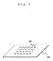
As shown in Fig. 6 by way of example, holes which serve as
cell culture regions may be of uniform or approximately
uniform size and can be arranged on a substrate 601 as a
plurality of cell culture regions 602 in the pattern of being
spaced at equal intervals. Otherwise, as shown in Fig. 7,
cell culture regions 702, 703, 704, 705 and 706 may be provided
on the substrate 701 as holes which are gradually varied in
size. Fig. 8 is a schematic view showing the status of culture
of cells 803 and 805 in the holes of cell culture regions 802
and 804 having different sizes. At this time, the number of
cells in each of the holes is one, but the holes differ from
each other in cell density which is obtained by dividing the
number of cells in a hole by the volume of the hole. In this
manner, by controlling the volume of each hole, it is possible
to observe various reactions of the same number of cells for
different densities.
It goes without saying that the arrangement pattern and
number of holes which serve as cell culture regions, as well
as the sizes and shapes of the holes may be suitably
determined.
According to the invention of this application, for
example, by changing the size (diameter) of a hole of a cell
culture region, it is possible to change the extent of the
mean free path of a cell which is an objective target, or by
changing the number of objective target cells to be placed
into holes of the same size (diameter), it is possible to
change the cell density of each of the holes. In addition,
if the shape of a hole for cell culture is changed, it is
possible to observe the influence and effect of the shape on
a cell.
According to the invention of this application, as shown
in Fig. 9 by way of example, a plurality of holes serving as
cell culture regions 902 and grooves 903 interconnecting
these holes and serving as thin passages each of which allows
one cell to narrowly pass therethrough may be provided on the
surface of a substrate 901. By providing the grooves 903
serving as such passages, it is possible to measure, for
example, the moving velocity, runnability and the like of
cells. In addition, it is possible to transfer a cell from
each of the cell culture region holes to an adjacent one via
a passage by using particle trapping means such as optical
tweezers. By using optical tweezers, it is possible to
isolate or select cells, and it is possible to cause
particular cells to interact with one another in a hole, as
well as it is possible to control the number of cells in a
hole.
Fig. 10 is a schematic plan view showing the
manipulation of such cell movement. Holes serving as cell
culture regions 1002 and grooves 1003 serving as passages for
interconnecting these holes are provided in a substrate 1001,
and a cell 1004 can be moved through the groove 1003 from a
hole A to another hole B of the cell culture regions 1002 by
optical tweezers 1005 means. The optical tweezers 1005 means
in this case is means which has heretofore been well known,
and is means for irradiating a target cell with a beam of laser
light to trap the cell and enabling the cell to be moved in
its trapped state with the movement of the beam of laser light.
According to the means of the optical tweezers 1005, as
shown in Fig. 11 by way of example, in a structure in which
a hole of a cell culture region 1102 provided in a substrate
1101 and a hole of a cell reservoir 1104 are made to
communicate with each other by a groove 1103 which serves as
a passage, a particular cell can be carried from the hole of
the cell reservoir 1104 to the hole of the cell culture region
1102 by the optical tweezers, and conversely, a particular
cell can also be transferred or discarded into the hole of
the cell reservoir 1104. Otherwise, as shown in Fig. 12 by
way of example, a single-cell purification culture system can
also be assembled on a cell culture region substrate 1201.
In this case, first of all, cells are introduced into a sample
introducing part 1202, and one of these cells is moved along
a groove by the use of trapping means such as optical tweezers,
and is guided to a cell culturing hole 1204. A cell trapping
hole 1203 is disposed in this groove at a halfway position
thereof to prevent a cell from swimming from 1202 into a hole
1204. Then, one cell which is in a particular state is again
taken out of a cell group cultured and grown from the one cell
in the hole 1204, and this cell is similarly moved by the use
of the trapping means, and is guided to a second culturing
hole 1206. Similarly, a cell trapping hole 1205 is disposed
at a halfway position. When the cell cultured in the hole
1206 grows to assume a certain predetermined state, cells are
carried to a cell observing hole 1208 through a cell carrying
groove 1207, and observation or the like is performed.
Fig. 13 shows one example of a culture container
different from the embodiment shown in Fig. 2. In this example,
a pipet 1307 is introduced from the outside, and is inserted
through a semi-permeable membrane 1304 to selectively collect
cells in a hole 1306. For this reason, a culture container
1301 is made open at its top, and a mineral oil 1312 is applied
to cover the top surface of a culture medium 1313 with which
the container is filled, thereby preventing the penetration
of unwanted microorganisms. The amount of the culture medium
to be introduced through a tube 1302 in the direction of an
arrow 1311 is made smaller than the amount of solution to be
sucked in the direction of an arrow 1317, and by the use of
a solution level regulating part 1315, when this solution
level becomes lower than a solution outlet 1316, air is sucked
to stop the suction of solution, and when the solution level
becomes higher to close the outlet 1316, the culture medium
is again sucked, so that the solution level is held at a
constant height. In this example, the solution level
regulating part is installed separately from the culture
container 105 so that ripples on a solution surface do not
influence optical observation. The pipet 1307 can be used
for sucking a cell, but can also be used for injecting a filler
to close a particular hole or groove or for introducing a
particular cell into a cell culture region through a
semi-permeable membrane. For example, the pipet 1307 can be
used in the case of introducing a particular sample into the
sample introducing part 1202 of the single-cell purification
culture system shown in Fig. 12. At this time, it is possible
to experiment the cell introduced by the pipet without any
problem of contamination, by moving the cell along the groove
toward the hole sealed with the semi-permeable membrane, by
trapping means such as optical tweezers before other cells
or the like penetrate through a cut in the semi-permeable
membrane. In addition, in the embodiment, since cells which
assume a particular state can be collected in units of one
cell with a pipet 1, gene polymorphism analysis, mRNA
expression analysis and the like can be also performed on this
one cell.
Fig. 14 shows an embodiment in which a reagent for
causing induction or the like is introduced into a cell in
a particular hole 1402. In this case, a pipet has a double
structure, and discharges a solution through an inside pipet
1411 and sucks a solution through an outside pipet 1412.
Accordingly, the structure of the pipet is such that the
solution discharged from the inside pipet 1411 is distributed
in the vicinity of only its outlet and is prevented from
leaking outwardly from the outside pipet 1412, by suction from
the outside pipet 1412. Accordingly, this pipet can be
brought to the vicinity of a particular hole and apply an
action to only a particular cell.
Incidentally, owing to the movement of cells by trapping
and moving means such as the above-described optical tweezers
according to the invention, it is possible to control the
density of particular cells in a hole of a cell culture region,
and it is also possible to implement identification of cells
which interact with one another, control of the time period
of interaction, and the like. However, the cell trapping and
moving means is not limited to the above-described optical
tweezers, and may also be, for example, means using ultrasonic
waves or means using electric fields.
Fig. 15 shows one embodiment in which a plurality of.
electrodes 1501, 1505 and 1508 are introduced in a cell
culture region substrate 1501. Since a cell has a peculiar
charge in a solution according to the state of the surface
thereof, when a positive charge is applied to an electrode
1502, a cell 1511 having the opposite charge can be attracted
to a hole 1503. By using this technique, cells corresponding
to different strengths of negative charges are gathered in
the hole 1503 and holes 1506 and 1509, respectively. In
addition, if negative charges are applied to the electrodes
1505 and 1508, cells cannot move between each of the holes.
Fig. 16 shows one example in which electrodes 1602 and
1603 are disposed on a cell culture region substrate 1601 and
ultrasonic vibrators 1604 and 1605 are disposed. In this
example, an electric field 1611 and an ultrasonic radiation
pressure 1612 are used as non-contact forces for manipulating
a cell. The electric field applies to a cell an external force
corresponding to the surface charge of the cell, while the
ultrasonic radiation pressure exerts over the cell an
external force corresponding to the size and hardness of the
cell. It is desirable that the frequency of an ultrasonic
wave to be used at this time be made a frequency of 1 MHz or
more so that the generation of bubbles (cavitation) can be
restrained. In this embodiment, specifically, the ultrasonic
radiation pressure and the electric field are respectively
made to act in different directions perpendicular to each
other, whereby cell distribution corresponding to the charge
and size of each cell can be two-dimensionally developed. In
addition, in this example, an external force due to an
electric field and an external force due to an ultrasonic wave
are combined on one substrate to perform separation according
to the kinds of cells, but external forces due to an electric
field and an ultrasonic wave may also be independently used
to transport a cell. Accordingly, it is possible to achieve
cell handling similar to that used with optical tweezers.
In the invention of this application, it is possible to
provide means for measuring the number of cells in a hole
serving as a cell culture region, and further, it is possible
to provide a pipet which can be inserted into a hole of a cell
culture region through a semi-permeable membrane and collect
a particular cell in the hole or inject or collect a reagent
or a filler in the hole. It goes without saying that various
other detailed practical forms can be used without being
limited to any of the above-described forms.
For example, as described above, in the apparatus for
microscopic observation of long-term culture of a single cell
according to this application, it is possible to obtain, for
example, the following superior advantages.
By using the above-described apparatus of this
application, as shown in Fig. 17 by way of example, in an
observation of E. coli growth, it has been confirmed that
there is no difference in growth speed and division length
between each generation and one E. coli bacterium divides into
two when reaching a two-fold length. On the other hand, as
shown in Fig. 18, it has been confirmed that growth depends
on the size, i.e., the volume, of a hole of a cell culture
region. In Fig. 18, "larger" indicates 2 × 10⁻⁷ ml, and "small"
indicates 2 × 10⁻⁹ ml.
As shown in Fig. 19, there is a difference in division
time between generations and between the numbers of initial
bacteria, and it has been confirmed that the first division
takes time until the beginning of division and one cell takes
long time until the beginning of division compared to the case
of a plurality of cells.
This feature can be realized exclusively by the
apparatus and the method according to the invention of this
application which enables long-term culture and microscopic
observation at the level of a single cell.
As described hereinabove in detail, according to the
invention of this application, by solving the problem of the
related art, there is provided novel technical means which
makes it possible to culture a cell group originating from
a particular single cell, to perform culture and observation
while identifying cells to be subjected to interaction during
the process of culturing cells, to spray a substance which
interacts with cells, for example, a drug such as a signal
substance, onto only a particular cell in a cell group which
is being cultured so that cells are cultured at a constant
cell density, and observe a difference in variation between
the particular cell and other cells. According to the
invention of this application, there is also provided novel
means which makes it possible to collect only a cell assuming
a particular state and perform analysis or biochemical
measurement of a gene of the cell, an expressed mRNA and the
like.
Claims (20)
- An apparatus for the microscopic observation of long-term culture of a single cell, which comprisesa cell culture container comprising a cell culture region consisting of a hole created on a substrate, a semi-permeable membrane covering the cell culture region and a culture medium exchange region on top of the semi-permeable membrane;a means for supplying culture medium to the cell culture container; andan optical microscopic means for long-term microscopic observation of a cell within the cell culture region.
- The apparatus for the microscopic observation of long-term culture of a single cell of claim 1, wherein the hole of the cell culture region has a diameter of 1 µm to 1 mm and a depth smaller than or equal to 100 µm.
- The apparatus for the microscopic observation of long-term culture of a single cell of claim 1, wherein the cell culture container is made of an optically transparent material.
- The apparatus for the microscopic observation of long-term culture of a single cell of claim 1, wherein the semi-permeable membrane is fixed to the top surface of the substrate by avidin-biotin bonding.
- The apparatus for the microscopic observation of long-term culture of a single cell of claim 1, wherein the semi-permeable membrane is an optical transparent membrane having a molecular weight of larger than or equal to 10,000 and a pore size smaller than or equal to 0.2 µm.
- The apparatus for the microscopic observation of long-term culture of a single cell of claim 1, wherein the cell culture region contains at least two holes created on the top surface of the substrate.
- The apparatus for the microscopic observation of long-term culture of a single cell of claim 6, wherein the hole of the cell culture region is connected to another hole by a passage through which a cell can pass, created on the top surface of the substrate.
- The apparatus for the microscopic observation of long-term culture of a single cell of claim 1, wherein the cell culture container further comprises a draining means, so that the culture medium supplied to the culture medium exchange region by the culture medium supplying means is exchanged with the used medium in the hole of the cell culture region through the semi-permeable membrane and the used medium is discharged by the draining means.
- The apparatus for the microscopic observation of long-term culture of a single cell of claim 1, which further comprises a valve for discharging gas remaining in the container.
- The apparatus for the microscopic observation of long-term culture of a single cell of claim 1, which further comprises a means for controlling the temperature of the culture medium.
- The apparatus for the microscopic observation of long-term culture of a single cell of claim 1, which further comprises a means for trapping and moving a cell.
- The apparatus for the microscopic observation of long-term culture of a single cell of claim 11, wherein the means for trapping and moving a cell is an optical tweezer.
- The apparatus for the microscopic observation of long-term culture of a single cell of claim 11, wherein ultrasonic wave is used as the means for trapping and moving a cell.
- The apparatus for the microscopic observation of long-term culture of a single cell of claim 11, wherein electric field is used as the means for trapping and moving a cell.
- The apparatus for the microscopic observation of long-term culture of a single cell of claim 1, which further comprises a pipet for spraying reagents into the hole of the cell culture region and for collecting the reagent.
- The apparatus for the microscopic observation of long-term culture of a single cell of claim 1, which further comprises a filter inserted into the optical path of the optical microscopic means to enable fluorescence observation of the cell.
- The apparatus for the microscopic observation of long-term culture of a single cell of claim 1, which further comprises a means for acquiring image data, a means for recognizing the shape of a particular cell in the image data, and a means for controlling the position of the stage and the focal length of an objective lens to maintain the particular cell in the center of the visual field.
- The apparatus for the microscopic observation of long-term culture of a single cell of claim 1, which further comprises a means for measuring the number of cells in the hole of the cell culture region.
- The apparatus for the microscopic observation of long-term culture of a single cell of claim 1 or 15, which further comprises a pipet that can be inserted into the hole of the cell culture region through the semi-permeable membrane for collecting a particular cell from the hole or for injecting reagents and filling materials to the hole.
- A method for the microscopic observation of long-term culture of a single cell, which comprises the use of the apparatus of claims 1 to 19.
Applications Claiming Priority (3)
| Application Number | Priority Date | Filing Date | Title |
|---|---|---|---|
| JP2000356827 | 2000-11-22 | ||
| JP2000356827A JP4002720B2 (en) | 2000-11-22 | 2000-11-22 | Single cell long-term culture microscope |
| PCT/JP2001/010215 WO2002042411A1 (en) | 2000-11-22 | 2001-11-22 | Apparatus for microscopic observation of long-term culture of single cell |
Publications (2)
| Publication Number | Publication Date |
|---|---|
| EP1344817A1 true EP1344817A1 (en) | 2003-09-17 |
| EP1344817A4 EP1344817A4 (en) | 2006-08-23 |
Family
ID=18828988
Family Applications (1)
| Application Number | Title | Priority Date | Filing Date |
|---|---|---|---|
| EP01997537A Withdrawn EP1344817A4 (en) | 2000-11-22 | 2001-11-22 | APPARATUS FOR MICROSCOPIC OBSERVATION OF SUSTAINABLE CULTURE OF A SINGLE CELL |
Country Status (5)
| Country | Link |
|---|---|
| US (1) | US7092154B2 (en) |
| EP (1) | EP1344817A4 (en) |
| JP (1) | JP4002720B2 (en) |
| KR (1) | KR100476273B1 (en) |
| WO (1) | WO2002042411A1 (en) |
Cited By (8)
| Publication number | Priority date | Publication date | Assignee | Title |
|---|---|---|---|---|
| US7482577B2 (en) | 2002-07-31 | 2009-01-27 | Arryx, Inc. | System and method of sorting materials using holographic laser steering |
| EP1544287A4 (en) * | 2002-08-23 | 2010-12-08 | Jsr Corp | Apparatus for cell reaction examination and method of cell reaction examination |
| US8008069B2 (en) | 2003-02-26 | 2011-08-30 | Japan Science And Technology Agency | Apparatus and method for machining microchamber for cell culture |
| CN103649302A (en) * | 2011-07-15 | 2014-03-19 | 独立行政法人科学技术振兴机构 | Cell culture device, device for long-term monitoring of cell culture, method for long-term cell culture, and method for long-term monitoring of cell culture |
| WO2018065772A1 (en) * | 2016-10-07 | 2018-04-12 | University Court Of The University Of St Andrews | Light sheet imaging with acoustic trapping |
| CN107991769A (en) * | 2018-01-12 | 2018-05-04 | 凝辉(天津)科技有限责任公司 | Two-dimensional scan device |
| CN110124763A (en) * | 2019-05-15 | 2019-08-16 | 林伟阳 | A kind of stem cell solution method for full automatically subpackaging |
| US20220403315A1 (en) * | 2019-09-30 | 2022-12-22 | OminiWell Pty Ltd. | Three-dimensional cell culture platform and uses thereof |
Families Citing this family (69)
| Publication number | Priority date | Publication date | Assignee | Title |
|---|---|---|---|---|
| US7150834B2 (en) | 2003-07-31 | 2006-12-19 | Arryx, Inc. | Multiple laminar flow-based rate zonal or isopycnic separation with holographic optical trapping of blood cells and other static components |
| US7699767B2 (en) | 2002-07-31 | 2010-04-20 | Arryx, Inc. | Multiple laminar flow-based particle and cellular separation with laser steering |
| US11243494B2 (en) | 2002-07-31 | 2022-02-08 | Abs Global, Inc. | Multiple laminar flow-based particle and cellular separation with laser steering |
| JP2004081086A (en) | 2002-08-26 | 2004-03-18 | Japan Science & Technology Corp | Cell culture microchamber |
| JP4370082B2 (en) * | 2002-08-26 | 2009-11-25 | 独立行政法人科学技術振興機構 | Neuron culture microchamber |
| JP4118102B2 (en) * | 2002-08-26 | 2008-07-16 | 独立行政法人科学技術振興機構 | Cell culture microchamber with semipermeable membrane |
| JP4048265B2 (en) * | 2002-08-26 | 2008-02-20 | 独立行政法人科学技術振興機構 | Single-cell long-term observation device |
| JP4216018B2 (en) * | 2002-08-26 | 2009-01-28 | 賢二 安田 | Nucleic acid recovery chip and nucleic acid recovery device |
| JP4171775B2 (en) * | 2002-08-26 | 2008-10-29 | 賢二 安田 | Nucleic acid analyzer |
| JP2004344003A (en) * | 2003-04-22 | 2004-12-09 | Institute Of Physical & Chemical Research | Cell stimulation device and cell stimulation method |
| EP1637587A4 (en) * | 2003-05-19 | 2009-08-05 | Japan Science & Tech Agency | MICROCHAMBRE FOR CELL CULTURE |
| JPWO2005090549A1 (en) * | 2004-03-19 | 2008-02-07 | ジェノミディア株式会社 | Microwell for cell culture |
| JP4535832B2 (en) * | 2004-10-13 | 2010-09-01 | 有限責任中間法人 オンチップ・セロミクス・コンソーシアム | Cell reconstitution device using heterogeneous cells and bioassay using the same |
| JP2006050975A (en) * | 2004-08-12 | 2006-02-23 | Kuraray Co Ltd | Cell manipulation substrate and perfusion culture apparatus using the same |
| JP4599937B2 (en) * | 2004-08-18 | 2010-12-15 | 株式会社ニコン | Automatic culture apparatus and automatic culture system |
| JP4033265B2 (en) * | 2004-10-29 | 2008-01-16 | 財団法人北九州産業学術推進機構 | Cell tissue microdevice |
| JP3981929B2 (en) * | 2004-10-29 | 2007-09-26 | 財団法人北九州産業学術推進機構 | Cell tissue microchip |
| JP4601423B2 (en) * | 2004-12-28 | 2010-12-22 | 独立行政法人科学技術振興機構 | Cell counting and separation chip |
| JP4894199B2 (en) * | 2005-02-17 | 2012-03-14 | 富士通株式会社 | Substance injection equipment |
| WO2007023711A1 (en) * | 2005-08-22 | 2007-03-01 | Waseda University | Microbe culturing apparatus, incubator and culturing method |
| US20070060724A1 (en) * | 2005-09-13 | 2007-03-15 | Nova Chemicals Corporation And Innovene Europe Ltd. | Enhanced catalyst productivity |
| US20070084706A1 (en) * | 2005-10-18 | 2007-04-19 | Shuichi Takayama | Microfluidic cell culture device and method for using same |
| US20070090166A1 (en) * | 2005-10-18 | 2007-04-26 | Shuichi Takayama | Microfluidic cell culture device |
| US8383395B2 (en) | 2005-11-01 | 2013-02-26 | Medinet Co., Ltd. | Cell culture apparatus, cell culture method, cell culture program and cell culture system |
| JP2007209219A (en) * | 2006-02-07 | 2007-08-23 | Olympus Corp | Biospecimen observation and measurement system and biospecimen observation and measurement method |
| US7595874B1 (en) | 2006-02-08 | 2009-09-29 | Sciperio, Inc. | Method of condensed cell slide preparation and detection of rarely occurring cells on microscope slides |
| US8980625B2 (en) | 2006-02-24 | 2015-03-17 | National Food Research Institute | Cell culture plate and method of manufacturing the same |
| EP2028264A4 (en) * | 2006-06-15 | 2012-10-24 | Nikon Corp | Cell incubator |
| JP4888767B2 (en) * | 2006-08-04 | 2012-02-29 | 独立行政法人科学技術振興機構 | Microincubator for microscopic observation |
| JP4861788B2 (en) * | 2006-10-11 | 2012-01-25 | キヤノン株式会社 | Biological specimen processing method and analysis method |
| WO2009111022A1 (en) | 2008-03-07 | 2009-09-11 | Corning Incorporated | Hydrophobically modified cellulose ether derivatives for cell culture and release |
| JP4574707B2 (en) * | 2008-10-20 | 2010-11-04 | 一般社団法人オンチップ・セロミクス・コンソーシアム | Cell sorting and culturing method and apparatus |
| CN101799467B (en) * | 2009-02-05 | 2013-10-23 | 深圳迈瑞生物医疗电子股份有限公司 | Particle analyzer, constant-temperature reaction system and constant-temperature reaction method |
| JP2011167151A (en) * | 2010-02-22 | 2011-09-01 | National Institute For Materials Science | Method for testing biodegradability, and material containing fullerene fiber for medical use |
| US10087408B2 (en) | 2010-07-07 | 2018-10-02 | The University Of British Columbia | System and method for microfluidic cell culture |
| US20130115606A1 (en) | 2010-07-07 | 2013-05-09 | The University Of British Columbia | System and method for microfluidic cell culture |
| JPWO2012043820A1 (en) * | 2010-09-30 | 2014-02-24 | 国立大学法人 東京医科歯科大学 | Method and apparatus for myocardial toxicity testing and cardiomyocyte evaluation |
| US10908066B2 (en) | 2010-11-16 | 2021-02-02 | 1087 Systems, Inc. | Use of vibrational spectroscopy for microfluidic liquid measurement |
| JP5610312B2 (en) * | 2011-12-22 | 2014-10-22 | 株式会社日立製作所 | Packaging container |
| JP2014113109A (en) * | 2012-12-11 | 2014-06-26 | Kawasaki Heavy Ind Ltd | Medium exchange system and medium heating apparatus |
| KR20140130279A (en) * | 2013-04-30 | 2014-11-10 | 나노바이오시스 주식회사 | Screening system for cell and solution condition |
| US8961904B2 (en) | 2013-07-16 | 2015-02-24 | Premium Genetics (Uk) Ltd. | Microfluidic chip |
| US11796449B2 (en) | 2013-10-30 | 2023-10-24 | Abs Global, Inc. | Microfluidic system and method with focused energy apparatus |
| CA2933017C (en) | 2013-12-12 | 2019-05-21 | Yamaha Hatsudoki Kabushiki Kaisha | A moving apparatus for moving a subject using tips |
| CN106068328B (en) | 2014-03-07 | 2019-11-26 | 古河电气工业株式会社 | Screening device and screening method |
| JP2015181405A (en) * | 2014-03-24 | 2015-10-22 | 東レエンジニアリング株式会社 | Apparatuses and methods for platelet production |
| JPWO2016027800A1 (en) * | 2014-08-22 | 2017-06-29 | オリンパス株式会社 | Cell culture bag, cell culture device and cell culture container |
| CN107430061B (en) | 2015-02-17 | 2020-11-06 | 埃克斯雷姆Ip英国有限责任公司 | Technology for temperature-controlled polarimeter sample chambers |
| SG11201706777QA (en) | 2015-02-19 | 2017-09-28 | Premium Genetics (Uk) Ltd | Scanning infrared measurement system |
| US10837977B2 (en) * | 2015-05-11 | 2020-11-17 | Kabushiki Kaisha Yaskawa Denki | Rack for dispensing and dispensing system |
| EP3351921A4 (en) * | 2015-09-14 | 2019-08-21 | National University Corporation Shiga University OF Medical Science | CELL SUPPORT SUBSTRATE SUPPORT FOR PREPARING AN OBSERVATION SAMPLE, AN ASSEMBLY COMPRISING THE SAME, AND METHOD FOR PREPARING AN OBSERVATION SAMPLE |
| KR101717085B1 (en) * | 2015-10-19 | 2017-03-20 | 가톨릭관동대학교산학협력단 | System for focused-ultrasound irradiation and realtime monitoring of cell culture |
| JP6387427B2 (en) * | 2017-01-31 | 2018-09-05 | ヤマハ発動機株式会社 | Object moving device |
| US11760965B2 (en) * | 2017-10-19 | 2023-09-19 | Georgia Tech Research Corporation | Mesofluidic device for culture of cell aggregates |
| WO2019226790A1 (en) | 2018-05-23 | 2019-11-28 | Abs Global, Inc. | Systems and methods for particle focusing in microchannels |
| CN109136411B (en) * | 2018-09-10 | 2022-07-22 | 河北工业大学 | Method and device for controlling bacteria colony |
| CN109238965A (en) * | 2018-09-25 | 2019-01-18 | 军事科学院系统工程研究院卫勤保障技术研究所 | A kind of dry chemical blood cell composition analysis optical system |
| EP3899489B1 (en) | 2018-12-21 | 2025-04-09 | ABS Global, Inc. | System and methods for sub-population identification |
| KR102235936B1 (en) * | 2019-02-13 | 2021-04-02 | 재단법인대구경북과학기술원 | Cell culturing system including ultrasound transducer |
| EP3955735B1 (en) | 2019-04-18 | 2024-05-22 | ABS Global, Inc. | System and process for continuous addition of cryoprotectant |
| US11628439B2 (en) | 2020-01-13 | 2023-04-18 | Abs Global, Inc. | Single-sheath microfluidic chip |
| CN112063502A (en) * | 2020-09-14 | 2020-12-11 | 于爱玲 | Biological culture device based on hemodialyzer |
| US12497648B2 (en) | 2020-10-21 | 2025-12-16 | Abs Global, Inc. | Methods and systems for processing genetic samples to determine identity or detect contamination |
| WO2022108840A1 (en) | 2020-11-23 | 2022-05-27 | Abs Global, Inc. | Modular flow cytometry systems and methods of processing samples |
| USD1118965S1 (en) | 2021-11-12 | 2026-03-17 | Abs Global, Inc. | Flow cytometry device |
| JP7772088B2 (en) * | 2021-12-08 | 2025-11-18 | Ntt株式会社 | Microorganism observation device and microorganism observation method |
| CN114875485B (en) * | 2022-05-18 | 2024-04-19 | 南平市鼎诚科技有限公司 | A process for growing diamonds in a laboratory and a manufacturing device thereof |
| JP7774806B2 (en) * | 2022-05-31 | 2025-11-25 | Ntt株式会社 | Soil microorganism observation device and observation method |
| CN118883437A (en) * | 2024-07-05 | 2024-11-01 | 四川百德生物科技有限公司 | A real-time detection device for living cells based on a micro-liquid and air flow system |
Family Cites Families (18)
| Publication number | Priority date | Publication date | Assignee | Title |
|---|---|---|---|---|
| US5328614A (en) * | 1979-05-21 | 1994-07-12 | Matsumura Kenneth N | Methods and apparati for removing protein-bound molecules from body fluids |
| DE3485462D1 (en) | 1983-11-08 | 1992-02-27 | Scient Diagnostics Inc | SYSTEM AND METHOD FOR CELL READING. |
| JPS60251879A (en) * | 1984-05-30 | 1985-12-12 | Hitachi Ltd | Cell cultivation system |
| GB2182727B (en) | 1985-11-12 | 1989-09-27 | Gen Electric | Propeller/fan pitch feathering apparatus |
| JPH053038Y2 (en) * | 1986-01-09 | 1993-01-25 | ||
| JPH0719927B2 (en) * | 1988-03-30 | 1995-03-06 | 工業技術院長 | Photoelectric conversion device using avidin-biotin system and manufacturing method thereof |
| JP3095464B2 (en) * | 1991-08-08 | 2000-10-03 | 宇宙開発事業団 | Cell culture device |
| DE69319427T2 (en) * | 1992-05-01 | 1998-12-10 | Univ Pennsylvania | ANALYSIS OF MEASURING THE FLOW RESISTANCE |
| US6216538B1 (en) | 1992-12-02 | 2001-04-17 | Hitachi, Ltd. | Particle handling apparatus for handling particles in fluid by acoustic radiation pressure |
| JP3488732B2 (en) | 1992-12-02 | 2004-01-19 | 株式会社日立製作所 | Ultrasonic processing equipment |
| US5665599A (en) * | 1994-12-01 | 1997-09-09 | Minuth; Will | Chamber for cultivating cells |
| JPH09289886A (en) | 1996-04-25 | 1997-11-11 | Shimadzu Corp | Cell membrane potential detector |
| JP3548761B2 (en) * | 1996-07-12 | 2004-07-28 | 株式会社東海ヒット | Transparent thermostatic culture vessel for microscope observation |
| JPH1156341A (en) * | 1997-08-20 | 1999-03-02 | Moritex Corp | Micro-specimen separation device and micro-specimen separation cell plate used therein |
| US6287765B1 (en) * | 1998-05-20 | 2001-09-11 | Molecular Machines, Inc. | Methods for detecting and identifying single molecules |
| US6587734B2 (en) * | 1998-11-04 | 2003-07-01 | Acorn Cardiovascular, Inc. | Cardio therapeutic heart sack |
| US6512580B1 (en) * | 1999-10-27 | 2003-01-28 | Verification Technologies, Inc. | Method and apparatus for portable product authentication |
| US6936067B2 (en) * | 2001-05-17 | 2005-08-30 | St. Jude Medical Inc. | Prosthetic heart valve with slit stent |
-
2000
- 2000-11-22 JP JP2000356827A patent/JP4002720B2/en not_active Expired - Fee Related
-
2001
- 2001-11-22 US US10/432,396 patent/US7092154B2/en not_active Expired - Fee Related
- 2001-11-22 WO PCT/JP2001/010215 patent/WO2002042411A1/en not_active Ceased
- 2001-11-22 EP EP01997537A patent/EP1344817A4/en not_active Withdrawn
- 2001-11-22 KR KR10-2003-7006901A patent/KR100476273B1/en not_active Expired - Fee Related
Cited By (13)
| Publication number | Priority date | Publication date | Assignee | Title |
|---|---|---|---|---|
| US7482577B2 (en) | 2002-07-31 | 2009-01-27 | Arryx, Inc. | System and method of sorting materials using holographic laser steering |
| EP1544287A4 (en) * | 2002-08-23 | 2010-12-08 | Jsr Corp | Apparatus for cell reaction examination and method of cell reaction examination |
| US8008069B2 (en) | 2003-02-26 | 2011-08-30 | Japan Science And Technology Agency | Apparatus and method for machining microchamber for cell culture |
| US8247222B2 (en) | 2003-02-26 | 2012-08-21 | Japan Science And Technology Agency | Micro-chamber processing apparatus for cell culture and method |
| CN103649302A (en) * | 2011-07-15 | 2014-03-19 | 独立行政法人科学技术振兴机构 | Cell culture device, device for long-term monitoring of cell culture, method for long-term cell culture, and method for long-term monitoring of cell culture |
| CN103649302B (en) * | 2011-07-15 | 2015-04-15 | 独立行政法人科学技术振兴机构 | Cell culture device, device for long-term monitoring of cell culture, method for long-term cell culture, and method for long-term monitoring of cell culture |
| WO2018065772A1 (en) * | 2016-10-07 | 2018-04-12 | University Court Of The University Of St Andrews | Light sheet imaging with acoustic trapping |
| CN107991769A (en) * | 2018-01-12 | 2018-05-04 | 凝辉(天津)科技有限责任公司 | Two-dimensional scan device |
| CN107991769B (en) * | 2018-01-12 | 2020-07-10 | 凝辉(天津)科技有限责任公司 | Two-dimensional scanning device |
| CN110124763A (en) * | 2019-05-15 | 2019-08-16 | 林伟阳 | A kind of stem cell solution method for full automatically subpackaging |
| CN110124763B (en) * | 2019-05-15 | 2021-07-02 | 哈尔滨工大国际干细胞工程研究院有限公司 | Full-automatic subpackaging method for stem cell solution |
| US20220403315A1 (en) * | 2019-09-30 | 2022-12-22 | OminiWell Pty Ltd. | Three-dimensional cell culture platform and uses thereof |
| US12454668B2 (en) * | 2019-09-30 | 2025-10-28 | OminiWell Pty Ltd. | Three-dimensional cell culture platform and uses thereof |
Also Published As
| Publication number | Publication date |
|---|---|
| JP4002720B2 (en) | 2007-11-07 |
| KR100476273B1 (en) | 2005-03-16 |
| US20040067482A1 (en) | 2004-04-08 |
| EP1344817A4 (en) | 2006-08-23 |
| US7092154B2 (en) | 2006-08-15 |
| WO2002042411A1 (en) | 2002-05-30 |
| JP2002153260A (en) | 2002-05-28 |
| KR20030062353A (en) | 2003-07-23 |
Similar Documents
| Publication | Publication Date | Title |
|---|---|---|
| US7092154B2 (en) | Apparatus for microscopic observation of long-term culture of single cell | |
| US11300496B2 (en) | Cell capture system and method of use | |
| JP7500560B2 (en) | Device and method for microdroplet detection of cells | |
| US9109197B2 (en) | Device for concentrating and separating cells | |
| US10391490B2 (en) | System and method for isolating and analyzing cells | |
| CN119955620B (en) | System and method for organoid culture | |
| WO2021084814A1 (en) | Minute particle collection method, microchip for aliquoting minute particles, minute particle collection device, production method for emulsion, and emulsion | |
| CN117280020A (en) | Devices and methods for cell culture | |
| JP2004337091A (en) | Cell culture apparatus | |
| JP4679847B2 (en) | Cell analysis method | |
| JP4840398B2 (en) | Antigen separation apparatus and antigen measurement method and apparatus using the same | |
| JP4171974B2 (en) | Antigen separation apparatus and antigen measurement method and apparatus using the same | |
| KR101877909B1 (en) | Biological material separator | |
| JP3665681B2 (en) | Micromanipulator and cell plate used for it | |
| US20250130157A1 (en) | Device and method to be carried out for examining and/or processing an in particular biological or medical sample | |
| JPH1156341A (en) | Micro-specimen separation device and micro-specimen separation cell plate used therein | |
| GB2638777A (en) | Improvements in or relating to a dispensing device | |
| HK40065856A (en) | System and method for organoid culture |
Legal Events
| Date | Code | Title | Description |
|---|---|---|---|
| PUAI | Public reference made under article 153(3) epc to a published international application that has entered the european phase |
Free format text: ORIGINAL CODE: 0009012 |
|
| 17P | Request for examination filed |
Effective date: 20030616 |
|
| AK | Designated contracting states |
Kind code of ref document: A1 Designated state(s): AT BE CH CY DE DK ES FI FR GB GR IE IT LI LU MC NL PT SE TR |
|
| RBV | Designated contracting states (corrected) |
Designated state(s): CH DE FR GB LI |
|
| RAP1 | Party data changed (applicant data changed or rights of an application transferred) |
Owner name: JAPAN SCIENCE AND TECHNOLOGY AGENCY |
|
| A4 | Supplementary search report drawn up and despatched |
Effective date: 20060725 |
|
| STAA | Information on the status of an ep patent application or granted ep patent |
Free format text: STATUS: THE APPLICATION HAS BEEN WITHDRAWN |
|
| 18W | Application withdrawn |
Effective date: 20070807 |