EP1342952A1 - Brenner, Verfahren zum Betrieb eines Brenners und Gasturbine - Google Patents
Brenner, Verfahren zum Betrieb eines Brenners und Gasturbine Download PDFInfo
- Publication number
- EP1342952A1 EP1342952A1 EP02005136A EP02005136A EP1342952A1 EP 1342952 A1 EP1342952 A1 EP 1342952A1 EP 02005136 A EP02005136 A EP 02005136A EP 02005136 A EP02005136 A EP 02005136A EP 1342952 A1 EP1342952 A1 EP 1342952A1
- Authority
- EP
- European Patent Office
- Prior art keywords
- burner
- combustion
- resonator
- fuel
- channel
- Prior art date
- Legal status (The legal status is an assumption and is not a legal conclusion. Google has not performed a legal analysis and makes no representation as to the accuracy of the status listed.)
- Withdrawn
Links
Images
Classifications
-
- F—MECHANICAL ENGINEERING; LIGHTING; HEATING; WEAPONS; BLASTING
- F23—COMBUSTION APPARATUS; COMBUSTION PROCESSES
- F23R—GENERATING COMBUSTION PRODUCTS OF HIGH PRESSURE OR HIGH VELOCITY, e.g. GAS-TURBINE COMBUSTION CHAMBERS
- F23R3/00—Continuous combustion chambers using liquid or gaseous fuel
- F23R3/28—Continuous combustion chambers using liquid or gaseous fuel characterised by the fuel supply
- F23R3/286—Continuous combustion chambers using liquid or gaseous fuel characterised by the fuel supply having fuel-air premixing devices
-
- F—MECHANICAL ENGINEERING; LIGHTING; HEATING; WEAPONS; BLASTING
- F23—COMBUSTION APPARATUS; COMBUSTION PROCESSES
- F23M—CASINGS, LININGS, WALLS OR DOORS SPECIALLY ADAPTED FOR COMBUSTION CHAMBERS, e.g. FIREBRIDGES; DEVICES FOR DEFLECTING AIR, FLAMES OR COMBUSTION PRODUCTS IN COMBUSTION CHAMBERS; SAFETY ARRANGEMENTS SPECIALLY ADAPTED FOR COMBUSTION APPARATUS; DETAILS OF COMBUSTION CHAMBERS, NOT OTHERWISE PROVIDED FOR
- F23M20/00—Details of combustion chambers, not otherwise provided for, e.g. means for storing heat from flames
- F23M20/005—Noise absorbing means
-
- F—MECHANICAL ENGINEERING; LIGHTING; HEATING; WEAPONS; BLASTING
- F23—COMBUSTION APPARATUS; COMBUSTION PROCESSES
- F23R—GENERATING COMBUSTION PRODUCTS OF HIGH PRESSURE OR HIGH VELOCITY, e.g. GAS-TURBINE COMBUSTION CHAMBERS
- F23R3/00—Continuous combustion chambers using liquid or gaseous fuel
- F23R3/02—Continuous combustion chambers using liquid or gaseous fuel characterised by the air-flow or gas-flow configuration
- F23R3/04—Air inlet arrangements
- F23R3/10—Air inlet arrangements for primary air
- F23R3/12—Air inlet arrangements for primary air inducing a vortex
- F23R3/14—Air inlet arrangements for primary air inducing a vortex by using swirl vanes
-
- F—MECHANICAL ENGINEERING; LIGHTING; HEATING; WEAPONS; BLASTING
- F23—COMBUSTION APPARATUS; COMBUSTION PROCESSES
- F23R—GENERATING COMBUSTION PRODUCTS OF HIGH PRESSURE OR HIGH VELOCITY, e.g. GAS-TURBINE COMBUSTION CHAMBERS
- F23R2900/00—Special features of, or arrangements for continuous combustion chambers; Combustion processes therefor
- F23R2900/00014—Reducing thermo-acoustic vibrations by passive means, e.g. by Helmholtz resonators
-
- Y—GENERAL TAGGING OF NEW TECHNOLOGICAL DEVELOPMENTS; GENERAL TAGGING OF CROSS-SECTIONAL TECHNOLOGIES SPANNING OVER SEVERAL SECTIONS OF THE IPC; TECHNICAL SUBJECTS COVERED BY FORMER USPC CROSS-REFERENCE ART COLLECTIONS [XRACs] AND DIGESTS
- Y02—TECHNOLOGIES OR APPLICATIONS FOR MITIGATION OR ADAPTATION AGAINST CLIMATE CHANGE
- Y02T—CLIMATE CHANGE MITIGATION TECHNOLOGIES RELATED TO TRANSPORTATION
- Y02T50/00—Aeronautics or air transport
- Y02T50/60—Efficient propulsion technologies, e.g. for aircraft
Definitions
- Burner method of operating a burner and gas turbine
- the invention relates to a burner with a burner duct into which combustion air can be introduced at an air introduction position and fuel at a fuel introduction position, the fuel introduction position being downstream of the air introduction position and wherein the combustion air can be mixed with the fuel in the burner duct and then introduced into a combustion zone.
- the burner is designed as a gas turbine burner.
- the invention also relates to a method for operating such a burner and a gas turbine, in particular with an annular combustion chamber.
- Combustion systems such as gas turbines, aircraft engines, rocket engines and heating systems can cause thermoacoustically induced combustion vibrations. These arise from an interaction of the combustion flame and the associated heat release with acoustic pressure fluctuations.
- the position of the flame, the flame front surface or the mixture composition can fluctuate due to acoustic excitation, which in turn leads to fluctuations in the heat release. With a constructive phase position, positive feedback and amplification can occur. Such an increased combustion vibration can lead to considerable noise pollution and damage from vibrations.
- thermoacoustically induced instabilities are significantly influenced by the acoustic properties of the combustion chamber and the boundary conditions at the combustion chamber inlet and outlet as well as at the combustion chamber walls.
- the acoustic properties can be changed by installing Helmholtz resonators.
- WO 93/10401 A1 shows a device for suppressing combustion vibrations in a combustion chamber of a gas turbine system.
- a Helmholtz resonator is fluidly connected to a fuel supply line.
- the acoustic properties of the supply line or of the overall acoustic system are changed such that combustion vibrations are suppressed.
- this measure is not sufficient in all operating states, since combustion vibrations can also occur if vibrations in the fuel line are suppressed.
- US-A-6 058 709 suggests introducing fuel at axially different positions in the combustion channel of a burner.
- constructive phase positions in the mixture composition are superimposed by destructive ones with regard to the formation of combustion vibrations, so that overall there are lower fluctuations and thus a reduced tendency to form combustion vibrations.
- This measure is, however, comparatively complex in terms of apparatus compared to the purely passive measure of using Helmholtz resonators.
- EP 0 597 138 A1 describes a gas turbine combustion chamber which has air-purged Helmholtz resonators in the area of the burners. These resonators absorb vibration energy from combustion vibrations occurring in the combustion chamber and the combustion vibrations are thereby damped.
- the object of the invention is to provide a burner with a particularly low tendency to form combustion vibrations. Another object of the invention is to provide a method for operating a burner which efficiently prevents combustion vibrations. Finally, it is also an object of the invention to provide a gas turbine with a particularly low tendency to form combustion vibrations.
- the object directed to a burner is achieved by specifying a burner with a burner channel into which combustion air can be introduced at an air introduction position and fuel at a fuel introduction position, the fuel introduction position being downstream of the air introduction position and the combustion air being miscible with the fuel in the burner channel and subsequently can be introduced into a combustion zone, a Helmholtz resonator being connected at the resonator position to the burner channel downstream of the fuel introduction position and upstream of the combustion zone directly in terms of flow technology in such a way that a coupling between fluctuations in the air ratio and combustion vibrations is largely broken.
- the air ratio is a quantity which is well known in combustion technology and proportionately characterizes the mixture composition of the mixture of combustion air and fuel by the ratio of the concentrations.
- the invention paved the way not only to dampen a combustion oscillation by means of a Helmholtz resonator, but also to prevent an essential reason for the generation of the combustion oscillation: the fluctuations in the air ratio.
- the fluctuation in the air ratio leads to acoustic impulses due to the inhomogeneous release of heat, which can lead to feedback and the build-up of a combustion oscillation as described above.
- By placing the Helmholtz resonator downstream of the fuel inlet acoustic disturbances at the fuel inlet position and thus fluctuations in the air ratio are reduced.
- the Helmholtz resonator at this resonator position can already prevent the combustion oscillation from occurring. In this way a much more efficient means against combustion vibrations is achieved.
- the burner channel surrounds a central channel as a ring channel, through which fuel and combustion air can be fed to the combustion zone separately from the ring channel, the Helmholtz resonator likewise surrounding the ring channel in a ring.
- the resonator can act completely and symmetrically on the ring channel. This avoids uneven temperature distributions. Due to the position downstream of the fuel supply, the resonator can also act directly on the location of the highest heat release, which leads to a particularly high effect of the resonator.
- the burner can in particular be a combined diffusion and premix burner.
- fuel is intimately mixed with combustion air in the ring channel as a premixing channel.
- the central channel is designed as a diffusion burner, in which air and fuel are only mixed in the combustion zone.
- a premix burner can burn little fuel in a lot of air through what is known as lean combustion and thus has low nitrogen oxide emissions.
- lean combustion is often unstable and tends to develop combustion vibrations.
- the ring-shaped Helmholtz resonator counteracts this.
- the diffusion burner burns a richer mixture and stabilizes the premix combustion, if necessary, but for the price of increased nitrogen oxide emissions.
- the burner duct can also be designed as a central duct and surrounded by an annular duct through which fuel and combustion air can be fed to the combustion zone separately from the central duct, the Helmholtz resonator surrounding the central duct in a ring.
- both the ring channel and the central channel Helmholtz resonators can each be arranged downstream of the fuel supply.
- Swirl blades are preferably arranged in the burner duct upstream of the resonator position.
- a swirl stabilizing the combustion is generated by such swirl blades.
- the fuel can more preferably be introduced via the swirl vanes.
- Combustion vibrations can preferably be absorbed or reflected by the Helmholtz resonator. While conventional resonators act exclusively through absorption, according to the concept of the invention, a reflective effect of the Helmholtz resonator can also reduce combustion vibrations, since, as stated above, reflection leads to a reduction in acoustic disturbances at the fuel inlet and thus to a reduction in fluctuations in the air ratio.
- the Helmholtz resonator preferably has an adjustable volume. This allows the acoustic properties to be set and the overall system to be acoustically coordinated. It is also conceivable to set the pressure, for example of air, in the resonator volume, which likewise changes the acoustic properties and what could even be set during operation.
- the Helmholz resonator preferably has a resonator volume and is connected to the burner channel via a resonator mouth, the resonator mouth being extended into the resonator volume by a tube. More preferably, several tubes protrude into the resonator volume. The internal volume of the resonator is hardly changed. The external dimensions of the resonator can thus be kept small. The tubes can be wound so that they are at a sufficient distance from the walls. By changing the length of the tubes, the damping device can be set to different frequencies that occur in the combustion system. The external dimensions of the resonator and thus of the firing insert and the open total cross-sectional area do not have to be changed. The main advantage: in order to attenuate low frequencies, the projecting tubes can be used to dispense with increasing the volume of the resonator.
- the burner is preferably designed as a gas turbine burner.
- the object directed to a gas turbine is achieved by specifying a gas turbine with a burner according to one of the embodiments described above.
- the advantages of such a gas turbine correspond to the advantages described for the burner according to the invention.
- Combustion vibrations in a gas turbine are particularly disruptive and harmful because of the high power densities.
- the gas turbine further preferably has an annular combustion chamber. In a ring combustion chamber, the large, coupled combustion chamber can easily lead to severe combustion vibrations.
- the object directed to a method is achieved by specifying a method for operating a burner with a burner duct in which the combustion air is at a Air introduction position and fuel are introduced at a fuel introduction position, the fuel introduction position being downstream of the air introduction position and wherein the combustion air is mixed with the fuel in the burner duct and then introduced into a combustion zone, and wherein a coupling between fluctuations in the air ratio and combustion vibrations is largely broken up by a Helmholtz resonator a resonator position with the burner channel downstream of the fuel introduction position and upstream of the combustion zone is directly connected in terms of flow technology in such a way that combustion vibrations do not penetrate to the fuel introduction position.
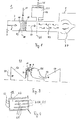
- FIG. 1 schematically shows a burner 1 and a method for operating the burner 1.
- the burner 1 has a burner channel 3.
- the burner duct 3 opens into a combustion chamber 5.
- Combustion air 9 is introduced into the burner duct 3 at an air introduction position 7.
- Fuel 11, in particular natural gas, is introduced into the burner duct 3 at a fuel introduction position 10 located downstream of the air introduction position 7. This is done via outlet openings 15 in swirl blades 13, which are arranged in the burner channel 3 and lead to stabilization of the combustion by generating a return flow region.
- the resulting mixture 17 of combustion air 9 and fuel 11 is then burned in the combustion chamber 5.
- a Helmholtz resonator 19 is connected via a resonator mouth 21 to the burner duct 3 directly in terms of flow technology at a resonator position 26.
- the Helmholtz resonator 19 has a resonator volume 23.
- the resonator volume 23 is adjustable via a piston 25.
- a Helmholtz resonator 19 combats a cause for the occurrence of a combustion oscillation 29 and not only dampens the amplitude of such combustion oscillations 29 by absorption.
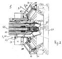
- a gas turbine burner 1 is shown in FIG.
- the burner channel 3 surrounds a central channel 41 as an annular channel 30.
- the annular channel 30 is designed as a premixing channel, in which fuel 11 and combustion air 9 prior to combustion be mixed intensively. This is known as premix combustion.
- the fuel 11 is introduced into the ring channel 30 via swirl blades 13 of hollow design.
- the central channel 41 opens into the combustion zone 27 together with a central fuel lance 45 which supplies fuel 47, in particular oil, via a swirl nozzle 47.
- fuel 11 and combustion air 9 are only mixed in the combustion zone 27 and one speaks of a diffusion combustion.
- fuel 11, in particular natural gas can also be added into the central channel 41 upstream of the combustion zone 27 via a fuel inlet 43.
- the ring channel 30 is surrounded in a ring shape by a Helmholtz resonator 19, which is directly connected to the ring channel 30 in terms of flow technology via hole-shaped resonator mouths 21.
- the central channel 41 is also directly connected to the central channel 41 by a Helmholtz resonator 20 via hole-shaped resonator openings 22.
- the respective Helmholtz resonator 19, 20 is arranged downstream of the respective fuel inlet position 10, with the effect described above.
- An additional resonator 31 is connected to the central channel 41 in terms of flow technology for further damping of combustion vibrations 29 via a slot-like resonator mouth 33.
- a gas turbine 51 is shown in FIG.
- the gas turbine 51 has a compressor 53, an annular combustion chamber 55 and a turbine part 57. Air 58 from the surroundings is fed to the compressor 53 and compressed there to combustion air 9. The combustion air 9 is then fed to the annular combustion chamber 55. It is burned there with fuel 11 to a hot gas 59 via gas turbine burner 1 of the type described above. The hot gas 59 drives the turbine part 57.
- FIG. 4 shows a Helmholtz resonator 19 with a resonator volume 23 and a resonator mouth 21, which consists of several Bores 21A exist.
- Each of the bores 21A is continued into the resonator volume 23 via a respective tube 61.
- the tubes 61 thus protrude into the resonator volume 23.
- the internal volume of the resonator is hardly changed.
- the external dimensions of the resonator 19 can thus be kept small.
- the tubes 61 can be made twisted to have enough distance from the walls. By changing the length of the tubes 61, the damping device can be adjusted to any frequency that occurs in the combustion system.
- the external dimensions of the resonator 19 and thus the firing insert and the open total cross-sectional area need not be changed.
- the main advantage around low frequencies. to dampen, with the help of the protruding tubes 61 there is no need to increase the volume of the resonator 19.
- the resonator 19 is flushed with air via air inlet openings 63. On the one hand, cooling of the resonator 19 is possible, on the other hand, the impedance of the resonator 19 can be set via the flow rate of air.
Landscapes
- Engineering & Computer Science (AREA)
- Chemical & Material Sciences (AREA)
- Combustion & Propulsion (AREA)
- Mechanical Engineering (AREA)
- General Engineering & Computer Science (AREA)
Priority Applications (6)
| Application Number | Priority Date | Filing Date | Title |
|---|---|---|---|
| EP02005136A EP1342952A1 (de) | 2002-03-07 | 2002-03-07 | Brenner, Verfahren zum Betrieb eines Brenners und Gasturbine |
| US10/506,122 US7320222B2 (en) | 2002-03-07 | 2003-02-28 | Burner, method for operating a burner and gas turbine |
| DE50312830T DE50312830D1 (de) | 2002-03-07 | 2003-02-28 | Brenner, verfahren zum betrieb eines brenners und gasturbine |
| ES03743358T ES2346865T3 (es) | 2002-03-07 | 2003-02-28 | Quemador, metodo para operar un quemador y turbina de gas. |
| PCT/EP2003/002079 WO2003074937A1 (de) | 2002-03-07 | 2003-02-28 | Brenner, verfahren zum betrieb eines brenners und gasturbine |
| EP03743358A EP1481195B1 (de) | 2002-03-07 | 2003-02-28 | Brenner, verfahren zum betrieb eines brenners und gasturbine |
Applications Claiming Priority (1)
| Application Number | Priority Date | Filing Date | Title |
|---|---|---|---|
| EP02005136A EP1342952A1 (de) | 2002-03-07 | 2002-03-07 | Brenner, Verfahren zum Betrieb eines Brenners und Gasturbine |
Publications (1)
| Publication Number | Publication Date |
|---|---|
| EP1342952A1 true EP1342952A1 (de) | 2003-09-10 |
Family
ID=27741144
Family Applications (2)
| Application Number | Title | Priority Date | Filing Date |
|---|---|---|---|
| EP02005136A Withdrawn EP1342952A1 (de) | 2002-03-07 | 2002-03-07 | Brenner, Verfahren zum Betrieb eines Brenners und Gasturbine |
| EP03743358A Expired - Lifetime EP1481195B1 (de) | 2002-03-07 | 2003-02-28 | Brenner, verfahren zum betrieb eines brenners und gasturbine |
Family Applications After (1)
| Application Number | Title | Priority Date | Filing Date |
|---|---|---|---|
| EP03743358A Expired - Lifetime EP1481195B1 (de) | 2002-03-07 | 2003-02-28 | Brenner, verfahren zum betrieb eines brenners und gasturbine |
Country Status (5)
| Country | Link |
|---|---|
| US (1) | US7320222B2 (es) |
| EP (2) | EP1342952A1 (es) |
| DE (1) | DE50312830D1 (es) |
| ES (1) | ES2346865T3 (es) |
| WO (1) | WO2003074937A1 (es) |
Cited By (4)
| Publication number | Priority date | Publication date | Assignee | Title |
|---|---|---|---|---|
| EP1746344A2 (de) * | 2005-07-20 | 2007-01-24 | Deutsches Zentrum für Luft- und Raumfahrt e.V. | Verfahren zur Einstellung der akustischen Eigenschaften einer Brennkammer |
| ITMI20122265A1 (it) * | 2012-12-28 | 2014-06-29 | Ansaldo Energia Spa | Gruppo bruciatore per una turbina a gas provvisto di risonatore di helmholtz |
| WO2015189101A1 (en) * | 2014-06-13 | 2015-12-17 | Siemens Aktiengesellschaft | Burner system with resonator |
| EP3438540A1 (en) * | 2017-07-31 | 2019-02-06 | Siemens Aktiengesellschaft | A burner including an acoustic damper |
Families Citing this family (28)
| Publication number | Priority date | Publication date | Assignee | Title |
|---|---|---|---|---|
| EP1645805A1 (de) * | 2004-10-11 | 2006-04-12 | Siemens Aktiengesellschaft | Brenner für fluidische Brennstoffe und Verfahren zum Betreiben eines derartigen Brenners |
| EP1762786A1 (de) * | 2005-09-13 | 2007-03-14 | Siemens Aktiengesellschaft | Verfahren und Vorrichtung zur Dämpfung thermo-akustischer Schwingungen, insbesondere in einer Gasturbine |
| US8127546B2 (en) * | 2007-05-31 | 2012-03-06 | Solar Turbines Inc. | Turbine engine fuel injector with helmholtz resonators |
| US9291104B2 (en) * | 2007-11-21 | 2016-03-22 | Mitsubishi Hitachi Power Systems, Ltd. | Damping device and gas turbine combustor |
| CH699322A1 (de) * | 2008-08-14 | 2010-02-15 | Alstom Technology Ltd | Verfahren zum einstellen eines helmholtz-resonators sowie helmholtz-resonator zur durchführung des verfahrens. |
| US8474265B2 (en) * | 2009-07-29 | 2013-07-02 | General Electric Company | Fuel nozzle for a turbine combustor, and methods of forming same |
| RU2508506C2 (ru) | 2009-09-01 | 2014-02-27 | Дженерал Электрик Компани | Способ и установка для ввода текучей среды в камеру сгорания газотурбинного двигателя |
| US9127837B2 (en) * | 2010-06-22 | 2015-09-08 | Carrier Corporation | Low pressure drop, low NOx, induced draft gas heaters |
| EP2474784A1 (en) | 2011-01-07 | 2012-07-11 | Siemens Aktiengesellschaft | Combustion system for a gas turbine comprising a resonator |
| GB201108917D0 (en) * | 2011-05-27 | 2011-07-13 | Rolls Royce Plc | A Hydraulic damping apparatus |
| US8469141B2 (en) | 2011-08-10 | 2013-06-25 | General Electric Company | Acoustic damping device for use in gas turbine engine |
| US9677766B2 (en) * | 2012-11-28 | 2017-06-13 | General Electric Company | Fuel nozzle for use in a turbine engine and method of assembly |
| US10088165B2 (en) * | 2015-04-07 | 2018-10-02 | General Electric Company | System and method for tuning resonators |
| US9400108B2 (en) | 2013-05-14 | 2016-07-26 | Siemens Aktiengesellschaft | Acoustic damping system for a combustor of a gas turbine engine |
| GB2516286B (en) * | 2013-07-18 | 2016-08-17 | Rolls Royce Plc | A duct and method for damping pressure waves caused by thermoacoustic instability |
| US9709279B2 (en) | 2014-02-27 | 2017-07-18 | General Electric Company | System and method for control of combustion dynamics in combustion system |
| US9709278B2 (en) | 2014-03-12 | 2017-07-18 | General Electric Company | System and method for control of combustion dynamics in combustion system |
| US9644846B2 (en) * | 2014-04-08 | 2017-05-09 | General Electric Company | Systems and methods for control of combustion dynamics and modal coupling in gas turbine engine |
| US9845956B2 (en) | 2014-04-09 | 2017-12-19 | General Electric Company | System and method for control of combustion dynamics in combustion system |
| CN106461222B (zh) | 2014-05-19 | 2019-03-15 | 西门子公司 | 具有共振器的燃烧器装置 |
| US9845732B2 (en) | 2014-05-28 | 2017-12-19 | General Electric Company | Systems and methods for variation of injectors for coherence reduction in combustion system |
| US10113747B2 (en) | 2015-04-15 | 2018-10-30 | General Electric Company | Systems and methods for control of combustion dynamics in combustion system |
| DE102015218677A1 (de) | 2015-09-29 | 2017-03-30 | Siemens Aktiengesellschaft | Brenneranordnung mit Resonator |
| EP3182008A1 (en) * | 2015-12-18 | 2017-06-21 | Ansaldo Energia IP UK Limited | Helmholtz damper for a gas turbine and gas turbine with such helmholtz damper |
| US10386074B2 (en) * | 2016-12-09 | 2019-08-20 | Solar Turbines Incorporated | Injector head with a resonator for a gas turbine engine |
| US20190093562A1 (en) * | 2017-09-28 | 2019-03-28 | Solar Turbines Incorporated | Scroll for fuel injector assemblies in gas turbine engines |
| CN113757720B (zh) * | 2021-09-18 | 2023-01-31 | 北京航空航天大学 | 燃烧振荡控制装置、方法及燃烧室 |
| US20230194090A1 (en) * | 2021-12-20 | 2023-06-22 | General Electric Company | Combustor with resonator |
Citations (5)
| Publication number | Priority date | Publication date | Assignee | Title |
|---|---|---|---|---|
| DE3329937A1 (de) * | 1982-08-30 | 1984-03-01 | Gerd Dr.-Ing. 4300 Essen Schäfer | Brenner fuer verfahren der autogen-technik, insbesondere schweissbrenner |
| WO1993010401A1 (de) * | 1991-11-15 | 1993-05-27 | Siemens Aktiengesellschaft | Einrichtung zur unterdrückung von verbrennungsschwingungen in einer brennkammer einer gasturbinenanlage |
| EP0597138A1 (de) * | 1992-11-09 | 1994-05-18 | Asea Brown Boveri Ag | Gasturbinen-Brennkammer |
| WO1999049264A1 (de) * | 1998-03-20 | 1999-09-30 | Siemens Aktiengesellschaft | Brenner und verfahren zur reduzierung von verbrennungsschwingungen beim betrieb |
| EP1004823A2 (de) * | 1998-11-10 | 2000-05-31 | Asea Brown Boveri AG | Dämpfungsvorrichtung zur Reduzierung der Schwingungsamplitude akustischer Wellen für einen Brenner |
Family Cites Families (10)
| Publication number | Priority date | Publication date | Assignee | Title |
|---|---|---|---|---|
| US3819009A (en) * | 1973-02-01 | 1974-06-25 | Gen Electric | Duct wall acoustic treatment |
| DE3241162A1 (de) * | 1982-11-08 | 1984-05-10 | Kraftwerk Union AG, 4330 Mülheim | Vormischbrenner mit integriertem diffusionsbrenner |
| JP3183053B2 (ja) * | 1994-07-20 | 2001-07-03 | 株式会社日立製作所 | ガスタービン燃焼器及びガスタービン |
| US5644918A (en) * | 1994-11-14 | 1997-07-08 | General Electric Company | Dynamics free low emissions gas turbine combustor |
| US6058709A (en) | 1996-11-06 | 2000-05-09 | The United States Of America Represented By The United States Department Of Energy | Dynamically balanced fuel nozzle and method of operation |
| EP0918190A1 (de) * | 1997-11-21 | 1999-05-26 | Abb Research Ltd. | Brenner für den Betrieb eines Wärmeerzeugers |
| DE19839085C2 (de) * | 1998-08-27 | 2000-06-08 | Siemens Ag | Brenneranordnung mit primärem und sekundärem Pilotbrenner |
| DE59810760D1 (de) * | 1998-12-15 | 2004-03-18 | Krasnojarskij Politekhn I Kras | Brennkammer mit akustisch gedämpftem Brennstoffversorgungssystem |
| US6351947B1 (en) * | 2000-04-04 | 2002-03-05 | Abb Alstom Power (Schweiz) | Combustion chamber for a gas turbine |
| GB2390150A (en) * | 2002-06-26 | 2003-12-31 | Alstom | Reheat combustion system for a gas turbine including an accoustic screen |
-
2002
- 2002-03-07 EP EP02005136A patent/EP1342952A1/de not_active Withdrawn
-
2003
- 2003-02-28 WO PCT/EP2003/002079 patent/WO2003074937A1/de not_active Application Discontinuation
- 2003-02-28 US US10/506,122 patent/US7320222B2/en not_active Expired - Lifetime
- 2003-02-28 ES ES03743358T patent/ES2346865T3/es not_active Expired - Lifetime
- 2003-02-28 DE DE50312830T patent/DE50312830D1/de not_active Expired - Lifetime
- 2003-02-28 EP EP03743358A patent/EP1481195B1/de not_active Expired - Lifetime
Patent Citations (5)
| Publication number | Priority date | Publication date | Assignee | Title |
|---|---|---|---|---|
| DE3329937A1 (de) * | 1982-08-30 | 1984-03-01 | Gerd Dr.-Ing. 4300 Essen Schäfer | Brenner fuer verfahren der autogen-technik, insbesondere schweissbrenner |
| WO1993010401A1 (de) * | 1991-11-15 | 1993-05-27 | Siemens Aktiengesellschaft | Einrichtung zur unterdrückung von verbrennungsschwingungen in einer brennkammer einer gasturbinenanlage |
| EP0597138A1 (de) * | 1992-11-09 | 1994-05-18 | Asea Brown Boveri Ag | Gasturbinen-Brennkammer |
| WO1999049264A1 (de) * | 1998-03-20 | 1999-09-30 | Siemens Aktiengesellschaft | Brenner und verfahren zur reduzierung von verbrennungsschwingungen beim betrieb |
| EP1004823A2 (de) * | 1998-11-10 | 2000-05-31 | Asea Brown Boveri AG | Dämpfungsvorrichtung zur Reduzierung der Schwingungsamplitude akustischer Wellen für einen Brenner |
Cited By (8)
| Publication number | Priority date | Publication date | Assignee | Title |
|---|---|---|---|---|
| EP1746344A2 (de) * | 2005-07-20 | 2007-01-24 | Deutsches Zentrum für Luft- und Raumfahrt e.V. | Verfahren zur Einstellung der akustischen Eigenschaften einer Brennkammer |
| EP1746344A3 (de) * | 2005-07-20 | 2011-07-13 | Deutsches Zentrum für Luft- und Raumfahrt e.V. | Verfahren zur Einstellung der akustischen Eigenschaften einer Brennkammer |
| ITMI20122265A1 (it) * | 2012-12-28 | 2014-06-29 | Ansaldo Energia Spa | Gruppo bruciatore per una turbina a gas provvisto di risonatore di helmholtz |
| WO2014102749A1 (en) * | 2012-12-28 | 2014-07-03 | Ansaldo Energia S.P.A. | Gas turbine burner assembly equipped with a helmholtz resonator |
| WO2015189101A1 (en) * | 2014-06-13 | 2015-12-17 | Siemens Aktiengesellschaft | Burner system with resonator |
| EP3438540A1 (en) * | 2017-07-31 | 2019-02-06 | Siemens Aktiengesellschaft | A burner including an acoustic damper |
| WO2019025094A1 (en) * | 2017-07-31 | 2019-02-07 | Siemens Aktiengesellschaft | BURNER COMPRISING AN ACOUSTICAL DAMPER |
| US11204166B2 (en) | 2017-07-31 | 2021-12-21 | Siemens Energy Global GmbH & Co. KG | Burner including an acoustic damper |
Also Published As
| Publication number | Publication date |
|---|---|
| EP1481195A1 (de) | 2004-12-01 |
| ES2346865T3 (es) | 2010-10-21 |
| DE50312830D1 (de) | 2010-08-05 |
| WO2003074937A1 (de) | 2003-09-12 |
| US7320222B2 (en) | 2008-01-22 |
| EP1481195B1 (de) | 2010-06-23 |
| US20050106519A1 (en) | 2005-05-19 |
Similar Documents
| Publication | Publication Date | Title |
|---|---|---|
| EP1481195B1 (de) | Brenner, verfahren zum betrieb eines brenners und gasturbine | |
| DE60105531T2 (de) | Gasturbinenbrennkammer, Gasturbine und Düsentriebwerk | |
| EP0985882B1 (de) | Schwingungsdämpfung in Brennkammern | |
| WO2003074936A1 (de) | Gasturbine | |
| EP0597138B1 (de) | Gasturbinen-Brennkammer | |
| DE69719688T2 (de) | Gasturbinenbrenner und Betriebsverfahren dafür | |
| EP0576697B1 (de) | Brennkammer einer Gasturbine | |
| EP1754002B1 (de) | Gestufter vormischbrenner mit einem injektor für flüssigbrennstoff | |
| DE4316475C2 (de) | Gasturbinen-Brennkammer | |
| DE102013108985A1 (de) | System und Verfahren zum Reduzieren von Verbrennungsdynamik | |
| DE102009026056A1 (de) | Brennkammerstruktur | |
| DE19640980B4 (de) | Vorrichtung zur Dämpfung von thermoakustischen Schwingungen in einer Brennkammer | |
| CH698007A2 (de) | Gestufte Mehrringdüse mit radialem Einlauf für mageres Vorgemisch und Zweistoff-Ringrohr-Brennkammer. | |
| EP1336800A1 (de) | Verfahren zur Verminderung verbrennungsgetriebener Schwingungen in Verbrennungssystemen sowie Vormischbrenner zur Durchführung des Verfahrens | |
| DE102013108725A1 (de) | System und Verfahren zur Reduktion von Verbrennungsdynamiken | |
| DE102009003639A1 (de) | Verfahren und Systeme zur Verminderung von Verbrennungsdynamik | |
| CH701454B1 (de) | Brenner mit einem Strömungskonditionierer. | |
| CH701461B1 (de) | Brennstoffdüsenanordnung für einen Gasturbinenmotor. | |
| EP1255074A1 (de) | Schwingungsreduktion in einer Brennkammer | |
| EP2187125A1 (de) | Vorrichtung und Verfahren zur Dämpfung von Verbrennungsschwingungen | |
| EP2383515B1 (de) | Brennersystem zur Dämpfung eines solchen Brennersystems | |
| EP2462379B1 (de) | Stabilisierung der flamme eines brenners | |
| WO1999046540A1 (de) | Brennkammer und verfahren zum betrieb einer brennkammer | |
| EP1137899B1 (de) | Verbrennungsvorrichtung und verfahren zur verbrennung eines brennstoffs | |
| EP3088802A1 (en) | Nozzle for a gas turbine combustor |
Legal Events
| Date | Code | Title | Description |
|---|---|---|---|
| PUAI | Public reference made under article 153(3) epc to a published international application that has entered the european phase |
Free format text: ORIGINAL CODE: 0009012 |
|
| AK | Designated contracting states |
Kind code of ref document: A1 Designated state(s): AT BE CH CY DE DK ES FI FR GB GR IE IT LI LU MC NL PT SE TR |
|
| AX | Request for extension of the european patent |
Extension state: AL LT LV MK RO SI |
|
| AKX | Designation fees paid | ||
| REG | Reference to a national code |
Ref country code: DE Ref legal event code: 8566 |
|
| STAA | Information on the status of an ep patent application or granted ep patent |
Free format text: STATUS: THE APPLICATION IS DEEMED TO BE WITHDRAWN |
|
| 18D | Application deemed to be withdrawn |
Effective date: 20040311 |