EP1342840B1 - Calandre et procédé de lissage d'une bande fibreuse - Google Patents
Calandre et procédé de lissage d'une bande fibreuse Download PDFInfo
- Publication number
- EP1342840B1 EP1342840B1 EP20030001198 EP03001198A EP1342840B1 EP 1342840 B1 EP1342840 B1 EP 1342840B1 EP 20030001198 EP20030001198 EP 20030001198 EP 03001198 A EP03001198 A EP 03001198A EP 1342840 B1 EP1342840 B1 EP 1342840B1
- Authority
- EP
- European Patent Office
- Prior art keywords
- web
- heat
- nip
- roll
- roller
- Prior art date
- Legal status (The legal status is an assumption and is not a legal conclusion. Google has not performed a legal analysis and makes no representation as to the accuracy of the status listed.)
- Expired - Fee Related
Links
Images
Classifications
-
- D—TEXTILES; PAPER
- D21—PAPER-MAKING; PRODUCTION OF CELLULOSE
- D21G—CALENDERS; ACCESSORIES FOR PAPER-MAKING MACHINES
- D21G1/00—Calenders; Smoothing apparatus
- D21G1/006—Calenders; Smoothing apparatus with extended nips
Definitions
- the invention relates to a calender for smoothing a fibrous web, in particular a paper or board web, with a broad nip formed by a roller and a jacket resting against it over a predetermined peripheral portion, and with a heating device. Furthermore, the invention relates to a method for smoothing a fibrous web, in particular a paper or board web, which is subjected to temperature and pressure in a nip, which is formed by a roller and a voltage applied thereto over a predetermined peripheral portion jacket.
- a broad nip formed by a roller and a mantle applied thereto over a predetermined peripheral portion has formed over a nip, which is formed by two rollers, the advantage that the residence time of the web in the nip is much longer.
- the compressive stress is lower even with otherwise equal forces than in a "normal" nip. It is therefore possible to use a wide nip for volume-saving smoothing of the web. This is particularly advantageous in the processing of cardboard webs.
- the jacket is pressed by means of a support shoe against the roller. He is so flexible that he can adapt to the curvature of the roller. The mantle is thus concave on a part of its circulation.
- the document EP 1 314 821 A2 which is prior art under Art. 54 (3) EPC, shows a calender for smoothing a fibrous web with a nip formed by a roll and a jacket resting against it over a predetermined peripheral portion, and with US Pat a heating device.
- the roller has a heat-insulating base, which is externally provided with a thin heat-conducting layer, which has a comparatively low heat capacity.
- the heater heats the surface layer.
- a heat balance between the web and the surface layer is at least substantially complete when the web leaves the nip.
- WO 95/10659 shows a calender.
- a roll of this calender has a base made of a steel alloy, on which a thinner surface layer is applied, which has a thickness of a few tenths of an inch and has an intimate contact with the surface of the hollow body.
- the surface layer may be formed of copper, for example.
- EP 0 258 169 A1 shows a press device for removing a liquid from a fibrous web.
- the fibrous web is passed through a press nip, which is formed between a roller and a circulating belt, wherein between the fibrous web and the circulating belt, a felt is guided.
- DE 39 37 246 A1 shows a calendering process in which a web is passed through a nip.
- the nip is formed by a heated roller and an elastically coated roller.
- the elastically coated roll is heated to a high temperature to smooth the web.
- the invention has for its object to avoid a Flashverdampfung at the exit of the broad nip.
- the roller has a heat-insulating body, which is externally provided with a thin heat-conducting layer whose heat capacity is low, the heat capacity of the heat-conducting layer and the speed of the web so are matched to one another that a heat transfer from the roller to the web is limited to a predetermined section of the broad nip and the surface temperature of the fibrous web at the exit of the broad nip is below 100 ° C.
- This residence time depends on the geometric extent of the broad nip and on the speed of the web passing through the nip.
- the heat transfer from the roller to the web can be determined in advance. You just have to Ensure that the heat transfer from the roller to the web is completed after a predetermined time, in which the web is still in the nip. The subsequent temperature compensation causes the web to cool sufficiently.
- the heat-conducting layer has a coefficient of thermal expansion which keeps a thermally induced change in width during operation below 1.3%. This avoids that the heat-conducting layer undergoes a change in width widthwise when it cools there due to the heat transfer to the web. Such a change in width could lead to wrinkles or other markings in the web.
- the load of the roller more specifically, the stress of the joint between the heat-conductive layer and the heat-insulating base body is kept small. Shear stresses that could lead to a detachment of the heat-conducting layer, occur practically not or only to a very small extent.
- the heater acts from the outside on the roller and / or the roller facing side of the web.
- the heater thus contributes heat from the outside into the heat-conducting layer. This is conveniently done just before the nip.
- a heat balance between the web and the heat-conducting layer which is associated with a temperature increase of the web and a reduction in temperature of the heat-conducting layer. Due to the relatively long residence time of the web in the nip resulting in temperature compensation operations over the cross section of the train.
- the web When entering the broad nip, the web can therefore thoroughly come into contact with a very hot heat-conducting layer of the roller, which has the corresponding positive effects on the smoothness of the surface. Since the web continues to rest on the very smooth surface of the roller during subsequent cooling of the web, the decrease in temperature does not result in any deterioration in the smoothness of the web. The smoothness once reached is rather “frozen", so that the web with the desired smoothness is present at the exit of the broad nip.
- the temperature compensation assumes that there is also a colder element in the elements forming the broad nip, for example the jacket. After a predetermined distance in the nip then a temperature compensation has taken place such that at the surface of the web, a temperature of 100 ° C is no longer reached.
- the heating device is designed as an inductive heating device.
- An inductive heating device has the advantage that it can apply in principle the entire cross section of the heat-conducting layer with an elevated temperature. The heat capacity of this layer is thus fully utilized.
- the length of the subsection is at most half the Breitnips.
- the web thus has the possibility to cool down over the other half, so that it is ensured that the web has a temperature of less than 100 ° C. at least at its surface at the outlet of the broad nip.
- the above object is achieved by limiting the heat transfer from the roller to the web to a predetermined section of the broad nip and brings the surface of the fibrous web to the exit of the broad nip below 100 ° C.
- this procedure makes use of the advantageous effects of an elevated temperature when processing the surface of the web.
- the elevated temperature is limited to a section at the beginning of the broad nip. Even within the broad nip, a complete temperature balance between the roller and the web at the surface takes place so that further heat transfer from the roller to the web is no longer possible.
- the web has the ability to effect a temperature compensation to colder areas of the broad nip, for example to the mantle, so that the vapor in the web can condense again to moisture.
- the roller is heated from the outside.
- the heat can be entered into the outer layer of the roller, wherein the heat absorption is limited by the heat capacity of this layer.
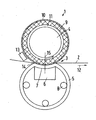
- the figure shows a calender 1 for smoothing a fibrous web 2, in particular a paper or board web, which will be referred to simply as "web" hereinafter.
- the web 2 runs for the purpose of smoothing through a nip 3, which is formed by a roller 4 and a jacket 5, which is pressed by means of a support shoe 6 against the circumference of the roller 4.
- the jacket 5 must be deformable so that it adapts to the curvature of the roller 4.
- the jacket 5 thus assumes a concave shape on a part of its circulation.
- the support shoe 6 has a pressure surface 7, which is provided in a manner not shown, but known per se with means for producing a lubrication.
- a pressure surface 7 is provided in a manner not shown, but known per se with means for producing a lubrication.
- openings may be provided here through which oil can escape in order to hydrostatically lubricate the contact surface between the support shoe 6 and the jacket 5.
- the jacket is guided over schematically illustrated guide rollers 8, so that it can rotate in the manner of a roller.
- Such a device is also referred to as a "shoe press”.
- the roller 4 has a heat-insulating base body 9, which is externally provided with a relatively thin layer 10 of a thermally conductive material.
- the base body 9 may consist of a plastic which is applied to a roller tube 11 and largely prevents heat transfer from the surface to the roller tube 11.
- the thin thermally conductive layer 10 may be formed of a metal, for example steel. It has due to their small extent only a very small heat capacity, but a very smooth surface.
- a heater 13 is arranged, which heats the surface of the roller 4 from the outside.
- the heater 13 is formed as an inductive heater, i. it generates by means of electrical and / or magnetic fields, for example eddy currents in the layer 10, which in turn lead to an increase in temperature of the layer 10.
- the heater 13 is arranged so close to the beginning 14 of the wide nip 3, that a significant cooling of the layer 10 has not yet taken place until entering the broad nip 3.
- the web 2 thus meets a relatively hot roller 4, when it enters the nip 3.
- the temperature of the surface of the roller 4 may well be in a range of 150 ° C to 200 ° C.
- a temperature compensation i. E. a heat transfer from the layer 10 to the web 2.
- the voltage applied to the roller 4 surface of the web 2 is heated very quickly.
- the associated high temperature and the smoothness of the surface of the layer 10 cause the web 2 is smoothed in any case on the voltage applied to the roller 4 side with high quality.
- the heat capacity of the layer 10 is relatively small, so that the heat transfer from the layer 10 to the web 2 is already completed a short time after entry into the nip 3.
- With a corresponding vote of the speed of the web 2 to the heat capacity of the layer 10 can ensure that the heat transfer to the web is limited to the first half of the broad nip 3.
- Within the web 2 is then carried out a temperature compensation to the colder side, so the jacket 5, so that the Surface temperature of the web 2 falls below the limit of 100 ° C.
- the layer 10 is formed of a material having a very small coefficient of thermal expansion. This avoids that the layer 10 contracts in the axial direction of the roller 4 when the layer 10 cools. Such a contraction could cause adverse phenomena in the web 2, such as wrinkles. Also, a stress on the connection between the layer 10 and the base body 9 could take place if the thermal expansion coefficient would be too large.
Landscapes
- Paper (AREA)
Claims (7)
- Calandre (1) pour lisser une bande fibreuse (2), notamment une bande de papier ou de carton, comprenant une pince allongée (3) qui est formée par un rouleau (4) et une enveloppe (5) s'appliquant sur celui-ci sur une portion périphérique prédéterminée, et comprenant un dispositif de chauffage (13), caractérisée en ce que le rouleau (4) présente un corps de base calorifuge (9) qui est pourvu à l'extérieur d'une mince couche (10) thermoconductrice, dont la capacité thermique est faible, la capacité thermique de la couche thermoconductrice (10) et la vitesse de la bande (2) étant adaptées l'une à l'autre de telle sorte qu'un transfert thermique du rouleau (4) à la bande (2) soit limité à une portion partielle prédéterminée de la pince allongée (3) et que la température en surface de la bande fibreuse (2) soit inférieure à 100°C à la sortie de la pince allongée (3).
- Calandre selon la revendication 1, caractérisée en ce que la couche thermoconductrice (10) présente un coefficient de dilatation thermique qui maintient en fonctionnement une variation de largeur due à la chaleur inférieure à 1,3%.
- Calandre selon la revendication 1 ou 2, caractérisée en ce que le dispositif de chauffage (13) agit de l'extérieur sur le rouleau (4) et/ou le côté de la bande (2) tourné vers le rouleau (4).
- Calandre selon la revendication 3, caractérisée en ce que le dispositif de chauffage (13) est réalisé sous forme de dispositif de chauffage inductif.
- Calandre selon l'une quelconque des revendications 1 à 4, caractérisée en ce que la longueur de la portion partielle correspond au maximum à la moitié de la pince allongée (3).
- Procédé de lissage d'une bande fibreuse (2), notamment d'une bande de papier ou de carton qui est sollicitée par la température et la pression dans une pince allongée (3) qui est formée par un rouleau (4) et une enveloppe (5) s'appliquant sur celui-ci sur une portion périphérique prédéterminée, caractérisé en ce que l'on limite le transfert thermique du rouleau (4) à la bande (2) à une portion partielle prédéterminée de la pince allongée (3) en utilisant un rouleau (4) avec un corps de base calorifuge (9) qui présente à l'extérieur une couche mince thermoconductrice (10) avec une faible capacité thermique et qui amène la surface de la bande fibreuse (2) jusqu'à la sortie de la pince allongée (3) en dessous de 100°C.
- Procédé selon la revendication 6, caractérisé en ce que l'on chauffe le rouleau depuis l'extérieur.
Applications Claiming Priority (2)
| Application Number | Priority Date | Filing Date | Title |
|---|---|---|---|
| DE10206027 | 2002-02-14 | ||
| DE2002106027 DE10206027C2 (de) | 2002-02-14 | 2002-02-14 | Kalander und Verfahren zum Glätten einer Faserstoffbahn |
Publications (2)
| Publication Number | Publication Date |
|---|---|
| EP1342840A1 EP1342840A1 (fr) | 2003-09-10 |
| EP1342840B1 true EP1342840B1 (fr) | 2007-03-07 |
Family
ID=27674620
Family Applications (1)
| Application Number | Title | Priority Date | Filing Date |
|---|---|---|---|
| EP20030001198 Expired - Fee Related EP1342840B1 (fr) | 2002-02-14 | 2003-01-22 | Calandre et procédé de lissage d'une bande fibreuse |
Country Status (2)
| Country | Link |
|---|---|
| EP (1) | EP1342840B1 (fr) |
| DE (2) | DE10206027C2 (fr) |
Families Citing this family (1)
| Publication number | Priority date | Publication date | Assignee | Title |
|---|---|---|---|---|
| DE102010030327A1 (de) | 2010-06-22 | 2011-12-22 | Voith Patent Gmbh | Bahnbehandlungsvorrichtung zum Glätten einer Faserstoffbahn |
Family Cites Families (7)
| Publication number | Priority date | Publication date | Assignee | Title |
|---|---|---|---|---|
| US4738752A (en) * | 1986-08-12 | 1988-04-19 | Beloit Corporation | Heated extended nip press apparatus |
| DE3920204A1 (de) * | 1988-10-31 | 1990-05-10 | Escher Wyss Gmbh | Verfahren zum glaetten einer papier- oder kartonbahn |
| DE3937246C2 (de) * | 1988-11-11 | 2002-06-27 | Metso Paper Inc | Kalandrierverfahren |
| US4936970A (en) * | 1988-11-14 | 1990-06-26 | Ebonex Technologies, Inc. | Redox reactions in an electrochemical cell including an electrode comprising Magneli phase titanium oxide |
| JP2727135B2 (ja) * | 1993-10-13 | 1998-03-11 | ベロイト・テクノロジーズ・インコーポレイテッド | 高い熱拡散性を有するシエルを備えたインパルスドライヤロール |
| FI20000927A0 (fi) * | 2000-04-18 | 2000-04-18 | Valmet Corp | Menetelmä kartonkirainan kalanteroimiseksi |
| FI108554B (fi) * | 2000-07-04 | 2002-02-15 | Metso Paper Inc | Termotela |
-
2002
- 2002-02-14 DE DE2002106027 patent/DE10206027C2/de not_active Expired - Fee Related
-
2003
- 2003-01-22 DE DE50306710T patent/DE50306710D1/de not_active Expired - Lifetime
- 2003-01-22 EP EP20030001198 patent/EP1342840B1/fr not_active Expired - Fee Related
Also Published As
| Publication number | Publication date |
|---|---|
| DE10206027C2 (de) | 2003-12-11 |
| EP1342840A1 (fr) | 2003-09-10 |
| DE50306710D1 (de) | 2007-04-19 |
| DE10206027A1 (de) | 2003-09-04 |
Similar Documents
| Publication | Publication Date | Title |
|---|---|---|
| DE69631683T2 (de) | Presspartie für eine papiermaschine mit einer breit-nip-presse | |
| EP0967324B1 (fr) | Procédé pour le lissage d' une bande de papier | |
| DE3920176C2 (fr) | ||
| DE4138788C2 (de) | Vorrichtung zur Entwässerung einer Faserstoffbahn | |
| AT506770B1 (de) | Walze | |
| EP1314819B1 (fr) | Calandre et procédé pour le lissage de bandes de papier ou carton | |
| EP1342840B1 (fr) | Calandre et procédé de lissage d'une bande fibreuse | |
| DE19824542B4 (de) | Walze, Kalander und Verfahren zum Betrieb einer Walze | |
| DE69721830T2 (de) | Verfahren und vorrichtung zur behandlung einer faserbahn | |
| EP1314820B1 (fr) | Calandre pour le lissage d' une bande fibreuse | |
| DE19822531B4 (de) | Kalanderwalze | |
| EP1314818B1 (fr) | Appareil et procédé pour lisser une bande de papier ou de carton | |
| DE10157694B4 (de) | Glättzylinderanordnung | |
| EP1318234B1 (fr) | Procédé et calandre pour le lissage d' une bande fibreuse | |
| DE10157686B4 (de) | Kalander und Verfahren zum Glätten einer Papier- oder Kartonbahn | |
| DE19911963A1 (de) | Verfahren zum Kalandern einer Papierbahn und ein Kalander nach diesem Verfahren | |
| EP1559831B1 (fr) | Calandre à pince allongée | |
| EP1318235B1 (fr) | Procédé et calandre pour le lissage d' une bande fibreuse | |
| EP1369527B1 (fr) | Calandre et procédé de calendrage | |
| EP1785524A1 (fr) | Dispositif de lissage d'une bande fibreuse | |
| EP1394320B1 (fr) | Dispositif de pressage | |
| EP1314667B2 (fr) | Méthode pour enrouler une bande de papier ou carton | |
| DE102006037358B4 (de) | Kalanderanordnung | |
| DE102020114812A1 (de) | Verfahren zum Herstellen eines flächigen Substrats | |
| EP2022892A2 (fr) | Bloc doté d'une calendre et d'un dispositif de séchage |
Legal Events
| Date | Code | Title | Description |
|---|---|---|---|
| PUAI | Public reference made under article 153(3) epc to a published international application that has entered the european phase |
Free format text: ORIGINAL CODE: 0009012 |
|
| 17P | Request for examination filed |
Effective date: 20030530 |
|
| AK | Designated contracting states |
Kind code of ref document: A1 Designated state(s): AT BE BG CH CY CZ DE DK EE ES FI FR GB GR HU IE IT LI LU MC NL PT SE SI SK TR |
|
| AX | Request for extension of the european patent |
Extension state: AL LT LV MK RO |
|
| AKX | Designation fees paid |
Designated state(s): DE FI SE |
|
| 17Q | First examination report despatched |
Effective date: 20050304 |
|
| GRAP | Despatch of communication of intention to grant a patent |
Free format text: ORIGINAL CODE: EPIDOSNIGR1 |
|
| RAP1 | Party data changed (applicant data changed or rights of an application transferred) |
Owner name: VOITH PATENT GMBH |
|
| GRAS | Grant fee paid |
Free format text: ORIGINAL CODE: EPIDOSNIGR3 |
|
| GRAA | (expected) grant |
Free format text: ORIGINAL CODE: 0009210 |
|
| AK | Designated contracting states |
Kind code of ref document: B1 Designated state(s): DE FI SE |
|
| REF | Corresponds to: |
Ref document number: 50306710 Country of ref document: DE Date of ref document: 20070419 Kind code of ref document: P |
|
| REG | Reference to a national code |
Ref country code: SE Ref legal event code: TRGR |
|
| PLBE | No opposition filed within time limit |
Free format text: ORIGINAL CODE: 0009261 |
|
| STAA | Information on the status of an ep patent application or granted ep patent |
Free format text: STATUS: NO OPPOSITION FILED WITHIN TIME LIMIT |
|
| 26N | No opposition filed |
Effective date: 20071210 |
|
| PGFP | Annual fee paid to national office [announced via postgrant information from national office to epo] |
Ref country code: SE Payment date: 20090114 Year of fee payment: 7 |
|
| EUG | Se: european patent has lapsed | ||
| PGFP | Annual fee paid to national office [announced via postgrant information from national office to epo] |
Ref country code: DE Payment date: 20120123 Year of fee payment: 10 |
|
| PGFP | Annual fee paid to national office [announced via postgrant information from national office to epo] |
Ref country code: FI Payment date: 20120625 Year of fee payment: 10 |
|
| PG25 | Lapsed in a contracting state [announced via postgrant information from national office to epo] |
Ref country code: SE Free format text: LAPSE BECAUSE OF NON-PAYMENT OF DUE FEES Effective date: 20100123 |
|
| PG25 | Lapsed in a contracting state [announced via postgrant information from national office to epo] |
Ref country code: FI Free format text: LAPSE BECAUSE OF NON-PAYMENT OF DUE FEES Effective date: 20130122 Ref country code: DE Free format text: LAPSE BECAUSE OF NON-PAYMENT OF DUE FEES Effective date: 20130801 |
|
| REG | Reference to a national code |
Ref country code: DE Ref legal event code: R119 Ref document number: 50306710 Country of ref document: DE Effective date: 20130801 |