EP1340917B2 - Magnetpumpe - Google Patents
Magnetpumpe Download PDFInfo
- Publication number
- EP1340917B2 EP1340917B2 EP01936856A EP01936856A EP1340917B2 EP 1340917 B2 EP1340917 B2 EP 1340917B2 EP 01936856 A EP01936856 A EP 01936856A EP 01936856 A EP01936856 A EP 01936856A EP 1340917 B2 EP1340917 B2 EP 1340917B2
- Authority
- EP
- European Patent Office
- Prior art keywords
- magnet
- impeller
- casing
- chamber
- outer rim
- Prior art date
- Legal status (The legal status is an assumption and is not a legal conclusion. Google has not performed a legal analysis and makes no representation as to the accuracy of the status listed.)
- Expired - Lifetime
Links
Images


Classifications
-
- F—MECHANICAL ENGINEERING; LIGHTING; HEATING; WEAPONS; BLASTING
- F04—POSITIVE - DISPLACEMENT MACHINES FOR LIQUIDS; PUMPS FOR LIQUIDS OR ELASTIC FLUIDS
- F04D—NON-POSITIVE-DISPLACEMENT PUMPS
- F04D13/00—Pumping installations or systems
- F04D13/02—Units comprising pumps and their driving means
-
- F—MECHANICAL ENGINEERING; LIGHTING; HEATING; WEAPONS; BLASTING
- F04—POSITIVE - DISPLACEMENT MACHINES FOR LIQUIDS; PUMPS FOR LIQUIDS OR ELASTIC FLUIDS
- F04D—NON-POSITIVE-DISPLACEMENT PUMPS
- F04D29/00—Details, component parts, or accessories
- F04D29/18—Rotors
- F04D29/20—Mounting rotors on shafts
-
- F—MECHANICAL ENGINEERING; LIGHTING; HEATING; WEAPONS; BLASTING
- F04—POSITIVE - DISPLACEMENT MACHINES FOR LIQUIDS; PUMPS FOR LIQUIDS OR ELASTIC FLUIDS
- F04D—NON-POSITIVE-DISPLACEMENT PUMPS
- F04D13/00—Pumping installations or systems
- F04D13/02—Units comprising pumps and their driving means
- F04D13/021—Units comprising pumps and their driving means containing a coupling
- F04D13/024—Units comprising pumps and their driving means containing a coupling a magnetic coupling
- F04D13/027—Details of the magnetic circuit
-
- F—MECHANICAL ENGINEERING; LIGHTING; HEATING; WEAPONS; BLASTING
- F04—POSITIVE - DISPLACEMENT MACHINES FOR LIQUIDS; PUMPS FOR LIQUIDS OR ELASTIC FLUIDS
- F04D—NON-POSITIVE-DISPLACEMENT PUMPS
- F04D29/00—Details, component parts, or accessories
- F04D29/40—Casings; Connections of working fluid
- F04D29/42—Casings; Connections of working fluid for radial or helico-centrifugal pumps
- F04D29/426—Casings; Connections of working fluid for radial or helico-centrifugal pumps especially adapted for liquid pumps
Definitions
- the present invention relates to a magnet pump, which includes a rotator consisting of an impeller and a magnet can, and a support means for rotatably supporting the rotator to rotationally drive the magnet can from outside a rear casing.
- a magnet pump which includes front and rear casings composed of synthetic resin.
- a magnet pump including front and rear casings composed of synthetic resin has been employed for the use of transferring a corrosive liquid, for example.
- the front casing forms a pumping chamber and the rear casing forms a cylindrical space contiguous to the pumping chamber.
- the cylindrical space in the rear casing is employed to locate a cylindrical magnet can that is rotatably supported by a support shaft, one end of which is secured on the rear casing.
- a rotary driver is located and magnetically coupled to the magnet can through the rear casing.
- the driving force from the rotary driver is employed to rotate the magnet can.
- the magnet can is integrally coupled to an impeller, which is housed in the pumping chamber. When the impeller rotates, a target fluid to be transferred is introduced into the inside of the pumping chamber through an inlet formed at the front of the front casing and discharged through an outlet formed at the side of the front casing.
- the rotator consisting of the magnet can and the impeller has a sliding portion, which is located at the inner diameter side in the vicinity of the impeller inlet. Therefore, if bubbles are mixed into the target fluid, the bubbles concentrate inwardly due to a difference in their specific gravity and invite an incomplete cooling action by the target fluid at the sliding portion, resulting in the sliding portion heated easily.
- a spindle boss arranged in the vicinity of the sliding portion has just a small clearance with peripheral members and hardly radiates heat.
- the conventional magnet pump with the synthetic resin casing causes a problem because the synthetic resin casing may be deformed or melted due to the heat caused by mixed bubbles and poor heat radiation.
- EP-A-0 778 658 discloses a magnet pump.
- EP 0 631 366 discloses a magnet pump according to the preamble of claim 1.
- the present invention has been made in consideration of such the problem and accordingly has an object to provide a magnet pump intended to avoid heating caused by mixed bubbles and poor heat radiation to improve the reliability.
- a magnet pump comprises a synthetic resin casing divided into a front casing and a rear casing and configured to internally form a first housing chamber, a second housing chamber contiguous thereto, and an eddy chamber along the outer rim of the first housing chamber, having an inlet formed at the first housing chamber and an outlet formed at the eddy chamber for a target fluid to be transferred; a substantially cylindrical magnet can with a follower magnet mounted on the outer rim thereof, housed in the second housing chamber of the casing; a support means for rotatably supporting the magnet can relative to the casing; a disk-like impeller fixed at the front end of the magnet can so as to rotate integrally with the magnet can, having a flow path formed inside to suck the target fluid from the center (for example, the front of the front casing), transfer the target fluid outward in the radial direction, and discharge the target fluid from the outer rim, and housed in the first housing chamber; and a rotational driving means magnetically coupled to the follower magnet through the casing
- the eddy chamber is formed at a position for dividing the casing into its constituents, or the front casing and the rear casing, along the outer rim of the first housing space to surround the outer rim of the impeller.
- the eddy chamber has overhangs formed at an entry thereof hanging over from both sides in the rotational-axis direction of the impeller. Therefore, if bubbles are mixed into the target fluid sucked from the center and discharged from the outer rim of the impeller, the bubbles discharged from the outer rim of the impeller can be prevented from returning to the first housing chamber along the outer surface of the impeller by the overhangs at the entry of the eddy chamber.
- the bubbles are effectively discharged from the outlet via the eddy chamber and bubbles staying in the vicinity of the sliding portion of the rotator can be reduced. This is effective to reduce heating caused by mixed bubbles at the sliding portion of the rotator, and prevent the synthetic resin casing from deforming and melting.
- the clearance between the outer rim of the impeller and the overhang in the eddy chamber is set slightly larger than the backlash movement of the impeller in the radial direction.
- the gap between the opposite tips of the overhangs is set larger than a distance that the outer rim of the impeller moves as the impeller moves in the axial direction. This allows the outlet on the outer rim of the impeller to be always contained within the gap sandwiched between the overhangs. If the gap between the overhangs is smaller than the distance, the overhangs interfere with the fluid discharged from the impeller. This is not preferable on pump performance.
- Another magnet pump comprises a synthetic resin casing divided into a front casing and a rear casing and configured to internally form a first housing chamber and a second housing chamber contiguous thereto, having an inlet and an outlet formed at the first housing chamber for a target fluid to be transferred; a substantially cylindrical magnet can with a follower magnet mounted on the outer rim thereof, housed in the second housing chamber of the casing; a support means for rotatably supporting the magnet can relative to the casing; a disk-like impeller fixed at the front end of the magnet can so as to rotate integrally with the magnet can, having a flow path formed inside to suck the target fluid from the center (for example, the front of the front casing), transfer the target fluid outward in the radial direction, and discharge the target fluid from the outer rim, and housed in the first housing chamber; and a rotational driving means magnetically coupled to the follower magnet through the casing for applying a rotational driving force to the impeller through the follower magnet, wherein a cooling hole
- the cooling hole is formed at the coupling portion between the magnet can and the impeller to flow the target fluid from the axial center thereof to the outside in the radial direction. Therefore, even if bubbles are mixed into the target fluid and the sliding portion of the support means is heated, the fluid and bubbles in the vicinity of the sliding portion can be discharged outside and agitated through the cooling hole. This is effective to reduce the heat caused from the sliding portion and prevent temperature elevations in the vicinity of the sliding portion.
- an eddy chamber is formed along the outer rim of the first housing space so as to surround the outer rim of the impeller.
- overhangs hanging over from both sides at the entry of the eddy chamber are formed in the rotational-axis direction of the impeller. This is further effective due to the above action to prevent the heating and poor heat radiation.
- the magnet can and the rear casing may be coupled by a pin passing through both in the radial direction.
- the fastening force at the fastened portion can not be reduced by vibrations, time variation or heat, or the inertial force when the pump reverses the direction of rotation or halts. Accordingly, it is possible to avoid various malfunctions such as sliding-heat to be caused when the magnet can and the impeller come loose, and to improve the reliability.
- the magnet can and the impeller can be easily disassembled and assembled and replaced on a part basis.
- the coupling plane between the magnet can and the impeller has rotational driving force transmission surfaces extending in the radial direction.
- the magnet can and the impeller can be fixed in the rotational direction (driving force transmission direction) mainly by the rotational driving force transmission surfaces without exerting a large load on the pin. This is effective to design the pin thinner and smaller accordingly.
- the support means for rotatably supporting the magnet can relative to the casing may be configured to include: a spindle, located in the second housing space, having a rear end supported by the rear end of the rear casing, and a front end supported by a shaft support that extends toward the center of the first housing space; and a cylindrical rotary bearing rotatably supported by the spindle and mounted on the inner rim in the magnet can.
- the support means may be configured to include: a spindle, located in the second housing space, having a rear end rotatably supported by the rear end of the rear casing, and a front end rotatably supported by a shaft support that extends toward the center of the first housing space, and mounted on the inner rim in the magnet can; a rear bearing for rotatably supporting the rear end of the spindle at the rear end of the rear casing; and a front bearing for rotatably supporting the front end of the spindle at the shaft support.
- Fig. 1 is a cross-sectional view showing the major part of a magnet pump according to an embodiment of the present embodiment.
- a synthetic resin casing 1 is divided into a front casing 2 and a rear casing 3 and internally forms an impeller housing chamber 4 or a first housing space and a magnet can housing chamber 5 or a second housing space contiguous thereto.
- the front casing 2 has an inlet 6 formed at the front and an outlet 7 formed at the upper part on the side.
- the inlet 6 and the outlet 7 communicate with the impeller housing chamber 4, respectively.
- a spindle 8 is located facing its front end toward the impeller housing chamber 4.
- the rear end of the spindle 8 is fixed on the rear end of the rear casing 3 and the front end of the spindle 8 is supported by a shaft support 9.
- This shaft support extends toward the center of the impeller housing chamber 4 from the inner surface at the inlet 6 of the front casing 2 in three directions, for example.
- a cylindrical magnet can 11 is housed in the magnet can housing chamber 5.
- the magnet can 11 is rotatably supported over the spindle 8 through a cylindrical rotary bearing 12 having a helical groove 12a formed in the inner surface.
- the magnet can 11 includes a cylinder 13 and a ring-shaped follower magnet 14 mounted over the outer surface of the cylinder 13.
- a disk-like impeller 21 is secured on the front end of the magnet can 11.
- the impeller 21 is internally provided with a flow path 24 that has an inlet 22 at the center of the front and an outlet 23 at the outer rim.
- the impeller 21 is housed in the impeller housing chamber 4 and, when it rotates, the target fluid is introduced through the inlets 6, 22 into the inside of the flow path 24 and discharged through the outlets 23, 7.
- a pin 31 which passes through them in the radial direction. This pin 31 restricts them from moving in the axial and rotational directions (only the axial direction if rotational driving force transmission surfaces 63, 64 are provided as described later). Also formed at the fitting portion between the magnet can 11 and the impeller 21 is a cooling hole 32, which passes through them in the radial direction.
- an eddy chamber 41 is formed surrounding the impeller 21 from the outer circumference.
- This eddy chamber 41 is formed along the outer circumference of the impeller housing chamber 4 at a position that divides the front casing 2 and the rear casing 3.
- the eddy chamber 41 has cross sections gradually enlarged from the inlet to the outlet in the rotational direction of the impeller 21 in accordance with the pump performance. Formed at an entry of the eddy chamber 41 or an end opposite to the outlet 23 of the impeller 21 are overhangs 41a, 41b, which hang over from both sides in the axial direction.
- An annular mouth ring 42 is provided at the front of the impeller 21.
- An annular front thrust bearing 43 is provided at a part opposite to the mouth ring 42 inside the front casing 2. The mouth ring 42 contacts the front thrust bearing 43 when the magnet can 11 slides forward during normal operation.
- a rear thrust bearing 44 is provided at a position on the spindle 8 opposite to the rear end of the rotary bearing 12. The rear end of the rotary bearing 12 contacts the rear thrust bearing 44 when the magnet can 11 slides backward during abnormal operation.
- a ring-shaped drive magnet 52 Located at a position on the magnet can 11 opposite to the follower magnet 14 through the rear casing 3 is a ring-shaped drive magnet 52, which is apart of a driving rotator 51 configuring a rotary driving means and is magnetically coupled to the follower magnet 14.
- the driving rotator 51 is driven via a driving shaft from a motor and the like, not depicted.
- the driving rotator 51 is isolated from the impeller housing chamber 4 and the magnet can housing chamber 5 and is housed within a space between the rear casing 3 and a driver casing 53.
- this magnet pump when the motor and the like, not depicted, rotationally drives the driving rotor 51 through the driving shaft to rotate the driving magnet 52, it rotates the follower magnet 52 that is magnetically coupled thereto. Subsequently, the rotary bearing 12 slides around the spindle 8 and the impeller 21 rotates to introduce the target fluid from the inlets 6, 22 into the flow path 24 in the impeller 21. The introduced target fluid is discharged outside through the outlets 23, 7.
- bubbles 55 may be mixed into the target fluid that is sucked through the inlet at the center of the impeller 21 and discharged from the outlet 23 in the outer rim.
- the bubbles 55 discharged from the impeller 21 and mixed into the eddy chamber 41 are prevented from returning to the impeller housing chamber 4 along the outer surface of the impeller 21.
- the bubbles 55 are forced to move in the circumferential direction within the eddy chamber 41 and discharged through the outlet 7.
- a clearance A between the outer rim of the impeller 21 and the overhang 41a, 41b of the eddy chamber 41 there is a clearance A between the outer rim of the impeller 21 and the overhang 41a, 41b of the eddy chamber 41. Desirably, this clearance A is determined slightly larger than the movement of the impeller 21 due to backlash in the radial direction: for example, less than 10 mm, preferably about 2 mm. Additionally, there is a clearance B in the axial direction between the tip of the overhang 41a and the inner front wall of the outlet 23 of the impeller 21.
- the clearance B is determined in consideration of an abrasion limit between the mouth ring 42 and the front thrust bearing 43 such that, even if the impeller 21 moves forward possibly in the axial direction, the inner front wall of the outlet 23 does not exceed forward beyond the tip of the overhang 41a.
- the clearance C is determined in consideration of a tolerable displacement of the impeller 21 in the axial direction such that, even if the impeller 21 moves backward possibly in the axial direction, the rear inner wall of the outlet 23 does not exceed backward beyond the tip of the overhang 41b.
- the overhang 41a exceeds backward beyond the inner front wall of the outlet 23, or if the overhang 41b exceeds forward beyond the inner rear wall of the outlet 23, the fluid discharged from the outlet 23 hits the overhangs 41a, 41b and the bubbles may be returned to the impeller housing chamber 4.
- the front casing 2 and the rear casing 3 are split at the center of the eddy chamber 41, so the overhangs 41a, 41b can be formed easily using normal resin molding tools.
- Fig. 3 shows a cross section illustrating the magnet can 11 seen from the axial direction of the coupling portion between the magnet can 11 and the impeller 21.
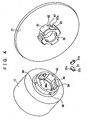
- Fig. 4 is a perspective view showing the impeller 11 and the magnet can 21 in a state before coupling.
- the outer rim of the rear end of the impeller 21 and the inner rim of the front end of the magnet can 11 they are fit with each other in the axial direction.
- Formed on the outer rim of the fitting portion of the impeller 21 are four protrusions 61, which are arrayed in the circumferential direction and protruded in the radial direction.
- Formed on the inner rim of the corresponding fitting portion of the magnet can 11 are recesses 62, which fit with the protrusions 61.
- holes 67, 68, 69 and notches 70 Formed in recesses 65 on the outer rim of the fitting portion of the impeller 21 and protrusions 66 of the magnet can 11 are holes 67, 68, 69 and notches 70, which pass through in the radial direction after both fit with each other. Among those, a pair of opposite holes 67, 68 are employed for fitting the pin 31, and the other hole 69 and the notch 70 are employed as the cooling hole 32 as shown in Fig. 3 .
- the pin 31 is placed from the inner rim of the fitting portion of the impeller 21 to the outer rim of the fitting portion of the magnet can 11 through the holes 67, 68 in the radial direction, passing through both.
- the pin 31 has a hexagonal hole 31a formed at the tip and a groove 31b formed at the bottom. It also has a protrusion 31c at the side.
- the hole 67 has a groove 67a formed to fit with the protrusion 31c of the pin 31.
- the hexagonal hole 31a is employed to rotate the pin 31 so that the protrusion 31c is engaged with a step 68a in the hole 68 to prevent the pin 31 from dropping off.
- a screw driver is employed to fit its tip into the groove 31b of the pin 31 from the outer rim to rotate the pin 31 while pressing it.
- the pin 31 may be pressed into from the outer rim.
- the cooling hole 32 forms a flow path for the fluid sucked through the inlet 22 at the center of the impeller 21 to be discharged from the inside to the outside of the fitting portion. Therefore, the fluid is prevented from staying at the center of the impeller 21 and the spindle 8 can be cooled effectively.
- Fig. 5 is a cross-sectional view showing the major part of a magnet pump according to another embodiment of the present embodiment.
- the support means for the magnet can 11 includes the fixed spindle 8 and the rotary bearing 12.
- the support means includes a spindle 81 serving as a rotary shaft fixed at the center of the magnet can 11, and bearings 82, 83 for rotatably supporting the both ends of the spindle 81.
- the bearing 82 is secured at the rear end of the rear casing 3 and the bearing 83 is secured on a shaft support 9 that extends from the inner rim of the front casing 2 to the center of the impeller housing chamber 4.
- the magnet can 11 and the impeller 21 are formed integrally, though they may be formed separately and secured by a pin and the like similar to the previous embodiment, needless to say.
- Other arrangements are same as those of the magnet pump in Fig. 1 and the same reference numerals are given to the corresponding parts to omit their detailed description.
- This embodiment also has the same basic operation as that of the previous embodiment.
- the eddy chamber is formed at the position for dividing the casing into its constituents, or the front casing and the rear casing, along the outer rim of the first housing space to surround the outer rim of the impeller.
- the eddy chamber has overhangs formed at the entry thereof hanging over from both sides in the rotational-axis direction of the impeller. Therefore, even if bubbles are mixed into the target fluid sucked from the center and discharged from the outer rim of the impeller, the bubbles discharged from the outer rim of the impeller can be prevented from returning to the first housing chamber along the outer surface of the impeller by the overhangs at the entry of the eddy chamber. This is effective to reduce heating at the sliding portion of the rotator caused by the mixed bubbles, and prevent the synthetic resin casing from deforming and melting.
- the cooling hole is formed at the coupling portion between the magnet can and the impeller to flow the target fluid from the axial center thereof to the outside in the radial direction. Therefore, even if bubbles are mixed into the target fluid and the sliding portion of the support means is heated, the high-temperature fluid and bubbles in the vicinity of the sliding portion can be discharged outside and agitated through the cooling hole. This is effective to reduce heat to be caused and prevent temperature elevations in the vicinity of the sliding portion.
Landscapes
- Engineering & Computer Science (AREA)
- Mechanical Engineering (AREA)
- General Engineering & Computer Science (AREA)
- Structures Of Non-Positive Displacement Pumps (AREA)
Claims (2)
- Magnetpumpe, die umfasst:ein Gehäuse (1), das in ein vorderes Gehäuse (2) und ein hinteres Kunstharzgehäuse (3) unterteilt und so gestaltet ist, dass es im Inneren eine erste Aufnahmekammer (4),eine zweite, daran angrenzende Aufnahmekammer (5), undeine Wirbelstromkammer (41) entlang des äußeren Randes der ersten Aufnahmekammer (4) bildet, die einen Einlass, der an der ersten Aufnahmekammer ausgebildet ist, und einen an der Wirbelstromkammer ausgebildeten Auslass für ein zu überführendes Ziel-Fluid aufweist;eine im Wesentlichen zylindrische Magnetdose (11) mit einem Folgemagneten (14), der an einem äußeren Rand derselben angebracht ist, und die in der zweiten Aufnahmekammer (5) des Gehäuses (1) aufgenommen ist;eine Trageeinrichtung (12), die die Magnetdose (11) drehbar relativ zu dem Gehäuse (1) trägt; ein scheibenartiges Pumpenrad (21), das an dem vorderen Ende der Magnetdose (11) so befestigt ist, dass es sich integral mit der Magnetdose (11) dreht, und das einen Strömungsweg (24) hat, der im Inneren ausgebildet ist, um das Ziel-Fluid aus der Mitte abzusaugen, das Ziel-Fluid in der radialen Richtung nach außen zu überführen und das Ziel-Fluid von einem äußeren Rand desselben auszustoßen, wobei es in der ersten Aufnahmekammer (4) aufgenommen ist; und eine Drehantriebseinrichtung (51, 52), die über das hintere Gehäuse (3) magnetisch mit dem Folgemagneten (14) gekoppelt ist, um eine Drehantriebskraft über den Folgemagneten (14) auf das Pumpenrad (21) auszuüben,wobei die Wirbelstromkammer (41) in dem Gehäuse (1) an einer Position ausgebildet ist, an der sie das vordere Gehäuse (2) und das hintere Gehäuse (3) unterteilt und den äußeren Rand des Pumpenrades (21) umgibt, und die Wirbelstromkammer (41) Überhänge (41 a, 41 b) aufweist, die an einem Eintritt in selbige ausgebildet sind und von beiden Seiten in der Drehachsenrichtung des Pumpenrades (21) überhängen,dadurch gekennzeichnet, dass das vordere Gehäuse (2) aus Kunstharz aufgebaut ist, und ein Kühlloch (32) an einem Kopplungsabschnitt zwischen der Magnetdose (11) und dem Pumpenrad (21) ausgebildet ist, um das Ziel-Fluid von der axialen Mitte desselben in der radialen Richtung nach außen zu leiten.
- Magnetpumpe nach Anspruch 1, dadurch gekennzeichnet, dass die Magnetdose (11) und das Pumpenrad (21) in der axialen Richtung zusammengesetzt und durch einen Stift (31) gekoppelt sind, der in der radialen Richtung durch beide hindurchtritt.
Priority Applications (1)
| Application Number | Priority Date | Filing Date | Title |
|---|---|---|---|
| DE60129590T DE60129590T3 (de) | 2001-06-05 | 2001-06-05 | Magnetpumpe |
Applications Claiming Priority (1)
| Application Number | Priority Date | Filing Date | Title |
|---|---|---|---|
| PCT/JP2001/004744 WO2002099283A1 (en) | 2001-06-05 | 2001-06-05 | Magnet pump |
Publications (4)
| Publication Number | Publication Date |
|---|---|
| EP1340917A1 EP1340917A1 (de) | 2003-09-03 |
| EP1340917A4 EP1340917A4 (de) | 2005-12-28 |
| EP1340917B1 EP1340917B1 (de) | 2007-07-25 |
| EP1340917B2 true EP1340917B2 (de) | 2011-08-31 |
Family
ID=11737402
Family Applications (1)
| Application Number | Title | Priority Date | Filing Date |
|---|---|---|---|
| EP01936856A Expired - Lifetime EP1340917B2 (de) | 2001-06-05 | 2001-06-05 | Magnetpumpe |
Country Status (7)
| Country | Link |
|---|---|
| US (1) | US6843645B2 (de) |
| EP (1) | EP1340917B2 (de) |
| JP (1) | JP4104542B2 (de) |
| KR (1) | KR20030023720A (de) |
| CN (1) | CN1199010C (de) |
| DE (1) | DE60129590T3 (de) |
| WO (1) | WO2002099283A1 (de) |
Families Citing this family (17)
| Publication number | Priority date | Publication date | Assignee | Title |
|---|---|---|---|---|
| AU2003235489A1 (en) * | 2002-05-08 | 2003-11-11 | Tom Mcneil | High efficiency solid-state light source and methods of use and manufacture |
| JP4554988B2 (ja) * | 2004-05-20 | 2010-09-29 | 株式会社荻原製作所 | シリンダ状マグネット型ポンプ |
| US7500829B2 (en) * | 2005-02-04 | 2009-03-10 | Sundyne Corporation | Two piece separable impeller and inner drive for pump |
| JP2006316678A (ja) * | 2005-05-11 | 2006-11-24 | Nidec Shibaura Corp | ポンプ |
| US20070109746A1 (en) * | 2005-11-15 | 2007-05-17 | Klein David A | Liquid cooling of electronic system and method |
| US20080112824A1 (en) * | 2006-11-09 | 2008-05-15 | Nidec Shibaura Corporation | Pump |
| DE102008008290A1 (de) * | 2008-02-07 | 2009-08-20 | H. Wernert & Co. Ohg | Laufradanordnung für eine Pumpe sowie Verfahren zum Herstellen einer solchen Laufradanordnung |
| GB2471908B (en) * | 2009-07-17 | 2011-11-16 | Hmd Seal Less Pumps Ltd | Non-intrusive vapour detector for magnetic drive pump |
| WO2011131251A1 (de) * | 2010-04-19 | 2011-10-27 | Pierburg Pump Technology Gmbh | Elektrische kfz-kühlmittelpumpe |
| DE102013014143A1 (de) * | 2012-12-21 | 2014-06-26 | Brose Fahrzeugteile GmbH & Co. Kommanditgesellschaft, Würzburg | Elektromotorische Wasserpumpe |
| JP6167037B2 (ja) * | 2013-12-24 | 2017-07-19 | 三鷹光器株式会社 | 断熱軸受構造 |
| CN106715264B (zh) * | 2016-10-28 | 2020-01-14 | 深圳市大疆创新科技有限公司 | 锁定机构、螺旋桨、电机、动力系统组件及飞行器 |
| CN108644127A (zh) * | 2018-07-11 | 2018-10-12 | 浙江融兴电动科技有限公司 | 一种水冷式无刷直流电机水泵 |
| JP7381418B2 (ja) | 2020-07-20 | 2023-11-15 | 株式会社ワールドケミカル | マグネットポンプ及びマグネットポンプ用回転体 |
| WO2022054403A1 (ja) * | 2020-09-14 | 2022-03-17 | 株式会社イワキ | インペラ及びこれを備えたポンプ |
| DE112022005371T5 (de) * | 2021-11-09 | 2024-09-05 | Litens Automotive Partnership | Elektrische Pumpe mit Leiterplatten-Stator |
| EP4215754B1 (de) * | 2022-01-25 | 2024-12-11 | Zi Yi Electrical Engineering Co., Ltd. | Spaltrohrmotorvorrichtung |
Family Cites Families (14)
| Publication number | Priority date | Publication date | Assignee | Title |
|---|---|---|---|---|
| US3221661A (en) * | 1961-12-18 | 1965-12-07 | Electronic Specialty Co | Low-suction head pumps |
| GB1496035A (en) * | 1974-07-18 | 1977-12-21 | Iwaki Co Ltd | Magnetically driven centrifugal pump |
| US4207485A (en) * | 1978-04-24 | 1980-06-10 | The Garrett Corporation | Magnetic coupling |
| JPS61101690U (de) * | 1984-12-08 | 1986-06-28 | ||
| CH672820A5 (de) * | 1986-03-21 | 1989-12-29 | Ernst Hauenstein | |
| US5064344A (en) * | 1989-11-01 | 1991-11-12 | Sundstrand Corporation | Partial throat diffuser |
| US5228832A (en) * | 1990-03-14 | 1993-07-20 | Hitachi, Ltd. | Mixed flow compressor |
| DK168236B1 (da) * | 1992-02-03 | 1994-02-28 | Thrige Pumper As | Køling af magnetkobling i pumper |
| US5464333A (en) * | 1993-06-24 | 1995-11-07 | Iwaki Co., Ltd. | Magnet pump with rear thrust bearing member |
| JP3384514B2 (ja) * | 1994-11-08 | 2003-03-10 | 大平洋機工株式会社 | タービンマグネット駆動ポンプ |
| JPH08166000A (ja) * | 1994-12-12 | 1996-06-25 | Iwaki:Kk | マグネットポンプ |
| EP0778658A1 (de) * | 1995-12-05 | 1997-06-11 | Ugimag S.A. | Detektor für asynchronische Bewegung in einer magnetischen Kupplung |
| US6074180A (en) * | 1996-05-03 | 2000-06-13 | Medquest Products, Inc. | Hybrid magnetically suspended and rotated centrifugal pumping apparatus and method |
| JPH11210669A (ja) * | 1998-01-21 | 1999-08-03 | Sogo Pump Seisakusho:Kk | 立形マグネットポンプ |
-
2001
- 2001-06-05 EP EP01936856A patent/EP1340917B2/de not_active Expired - Lifetime
- 2001-06-05 WO PCT/JP2001/004744 patent/WO2002099283A1/ja not_active Ceased
- 2001-06-05 CN CNB018134157A patent/CN1199010C/zh not_active Expired - Lifetime
- 2001-06-05 JP JP2003502373A patent/JP4104542B2/ja not_active Expired - Lifetime
- 2001-06-05 DE DE60129590T patent/DE60129590T3/de not_active Expired - Lifetime
- 2001-06-05 KR KR10-2003-7001278A patent/KR20030023720A/ko not_active Abandoned
- 2001-06-05 US US10/333,024 patent/US6843645B2/en not_active Expired - Lifetime
Also Published As
| Publication number | Publication date |
|---|---|
| CN1199010C (zh) | 2005-04-27 |
| JPWO2002099283A1 (ja) | 2004-09-16 |
| DE60129590T2 (de) | 2007-11-22 |
| DE60129590T3 (de) | 2012-01-12 |
| KR20030023720A (ko) | 2003-03-19 |
| CN1444702A (zh) | 2003-09-24 |
| WO2002099283A1 (en) | 2002-12-12 |
| EP1340917B1 (de) | 2007-07-25 |
| DE60129590D1 (de) | 2007-09-06 |
| US20040009079A1 (en) | 2004-01-15 |
| JP4104542B2 (ja) | 2008-06-18 |
| US6843645B2 (en) | 2005-01-18 |
| EP1340917A4 (de) | 2005-12-28 |
| EP1340917A1 (de) | 2003-09-03 |
Similar Documents
| Publication | Publication Date | Title |
|---|---|---|
| EP1340917B2 (de) | Magnetpumpe | |
| EP1120569B1 (de) | Magnetpumpe | |
| EP0631366B1 (de) | Magnetisch angetriebene Pumpe mit hinten angeordnetem Drucklagerelement | |
| CN101802411B (zh) | 用于屏蔽泵的泵转子 | |
| US8114008B2 (en) | Blood pump and pump unit | |
| US7033146B2 (en) | Sealed magnetic drive sealless pump | |
| US7566211B2 (en) | Vane pump having vanes with a cutout portion | |
| JP7103342B2 (ja) | ポンプ装置 | |
| US20210025394A1 (en) | Counterweight for compressor, motor for compressor and compressor | |
| JP2795689B2 (ja) | マグネットポンプ | |
| CN112840127B (zh) | 电动泵 | |
| JPH08166000A (ja) | マグネットポンプ | |
| TW507049B (en) | Magnetic pump | |
| CN115807786A (zh) | 排水泵 | |
| KR20030013187A (ko) | 비엘디씨 마그네트 펌프 | |
| JP2632132B2 (ja) | マグネットポンプにおけるリアスラスト軸受の構造 | |
| CN112204263A (zh) | 泵壳及包括其的磁力泵 | |
| JP6430557B2 (ja) | 電動オイルポンプ | |
| US12497968B2 (en) | Electric water pump | |
| KR200254640Y1 (ko) | 비엘디씨 마그네트 펌프 | |
| JPH11132160A (ja) | 内接ロータ型流体装置 | |
| JP3226844U (ja) | 渦巻ポンプ | |
| JPH0374599A (ja) | マグネットポンプ | |
| JP4430886B2 (ja) | マグネットポンプ | |
| EP0639723A1 (de) | Flüssigkeitsreibungskupplung |
Legal Events
| Date | Code | Title | Description |
|---|---|---|---|
| PUAI | Public reference made under article 153(3) epc to a published international application that has entered the european phase |
Free format text: ORIGINAL CODE: 0009012 |
|
| 17P | Request for examination filed |
Effective date: 20030204 |
|
| AK | Designated contracting states |
Kind code of ref document: A1 Designated state(s): DE FR GB |
|
| RIC1 | Information provided on ipc code assigned before grant |
Ipc: 7F 04D 13/02 A Ipc: 7F 04D 29/42 B |
|
| A4 | Supplementary search report drawn up and despatched |
Effective date: 20051110 |
|
| 17Q | First examination report despatched |
Effective date: 20060621 |
|
| GRAP | Despatch of communication of intention to grant a patent |
Free format text: ORIGINAL CODE: EPIDOSNIGR1 |
|
| GRAS | Grant fee paid |
Free format text: ORIGINAL CODE: EPIDOSNIGR3 |
|
| GRAA | (expected) grant |
Free format text: ORIGINAL CODE: 0009210 |
|
| AK | Designated contracting states |
Kind code of ref document: B1 Designated state(s): DE FR GB |
|
| REG | Reference to a national code |
Ref country code: GB Ref legal event code: FG4D |
|
| REF | Corresponds to: |
Ref document number: 60129590 Country of ref document: DE Date of ref document: 20070906 Kind code of ref document: P |
|
| PLBI | Opposition filed |
Free format text: ORIGINAL CODE: 0009260 |
|
| PLAX | Notice of opposition and request to file observation + time limit sent |
Free format text: ORIGINAL CODE: EPIDOSNOBS2 |
|
| 26 | Opposition filed |
Opponent name: RENNER GMBH Effective date: 20080424 |
|
| PLAF | Information modified related to communication of a notice of opposition and request to file observations + time limit |
Free format text: ORIGINAL CODE: EPIDOSCOBS2 |
|
| PLBB | Reply of patent proprietor to notice(s) of opposition received |
Free format text: ORIGINAL CODE: EPIDOSNOBS3 |
|
| APBM | Appeal reference recorded |
Free format text: ORIGINAL CODE: EPIDOSNREFNO |
|
| APBP | Date of receipt of notice of appeal recorded |
Free format text: ORIGINAL CODE: EPIDOSNNOA2O |
|
| APAH | Appeal reference modified |
Free format text: ORIGINAL CODE: EPIDOSCREFNO |
|
| APBU | Appeal procedure closed |
Free format text: ORIGINAL CODE: EPIDOSNNOA9O |
|
| PUAH | Patent maintained in amended form |
Free format text: ORIGINAL CODE: 0009272 |
|
| STAA | Information on the status of an ep patent application or granted ep patent |
Free format text: STATUS: PATENT MAINTAINED AS AMENDED |
|
| 27A | Patent maintained in amended form |
Effective date: 20110831 |
|
| AK | Designated contracting states |
Kind code of ref document: B2 Designated state(s): DE FR GB |
|
| REG | Reference to a national code |
Ref country code: DE Ref legal event code: R102 Ref document number: 60129590 Country of ref document: DE |
|
| REG | Reference to a national code |
Ref country code: DE Ref legal event code: R102 Ref document number: 60129590 Country of ref document: DE Effective date: 20110831 |
|
| REG | Reference to a national code |
Ref country code: FR Ref legal event code: PLFP Year of fee payment: 16 |
|
| REG | Reference to a national code |
Ref country code: FR Ref legal event code: PLFP Year of fee payment: 17 |
|
| REG | Reference to a national code |
Ref country code: FR Ref legal event code: PLFP Year of fee payment: 18 |
|
| PGFP | Annual fee paid to national office [announced via postgrant information from national office to epo] |
Ref country code: DE Payment date: 20200626 Year of fee payment: 20 Ref country code: FR Payment date: 20200620 Year of fee payment: 20 |
|
| PGFP | Annual fee paid to national office [announced via postgrant information from national office to epo] |
Ref country code: GB Payment date: 20200620 Year of fee payment: 20 |
|
| REG | Reference to a national code |
Ref country code: DE Ref legal event code: R071 Ref document number: 60129590 Country of ref document: DE |
|
| REG | Reference to a national code |
Ref country code: GB Ref legal event code: PE20 Expiry date: 20210604 |
|
| PG25 | Lapsed in a contracting state [announced via postgrant information from national office to epo] |
Ref country code: GB Free format text: LAPSE BECAUSE OF EXPIRATION OF PROTECTION Effective date: 20210604 |