EP1340709B1 - Installation de transport pour transporter des éléments de structure - Google Patents
Installation de transport pour transporter des éléments de structure Download PDFInfo
- Publication number
- EP1340709B1 EP1340709B1 EP02025922A EP02025922A EP1340709B1 EP 1340709 B1 EP1340709 B1 EP 1340709B1 EP 02025922 A EP02025922 A EP 02025922A EP 02025922 A EP02025922 A EP 02025922A EP 1340709 B1 EP1340709 B1 EP 1340709B1
- Authority
- EP
- European Patent Office
- Prior art keywords
- constructional
- transport system
- lifting
- constructional element
- transport
- Prior art date
- Legal status (The legal status is an assumption and is not a legal conclusion. Google has not performed a legal analysis and makes no representation as to the accuracy of the status listed.)
- Expired - Lifetime
Links
- 230000033001 locomotion Effects 0.000 claims description 35
- 230000007246 mechanism Effects 0.000 claims description 10
- 238000012546 transfer Methods 0.000 claims description 9
- 238000004519 manufacturing process Methods 0.000 claims description 6
- 238000010276 construction Methods 0.000 description 50
- 238000013461 design Methods 0.000 description 20
- 230000008901 benefit Effects 0.000 description 9
- 238000003466 welding Methods 0.000 description 6
- 238000012545 processing Methods 0.000 description 4
- 238000005452 bending Methods 0.000 description 3
- 238000006073 displacement reaction Methods 0.000 description 2
- 230000005540 biological transmission Effects 0.000 description 1
- 230000006835 compression Effects 0.000 description 1
- 238000007906 compression Methods 0.000 description 1
- 238000011161 development Methods 0.000 description 1
- 230000000694 effects Effects 0.000 description 1
- 230000005489 elastic deformation Effects 0.000 description 1
- 230000005611 electricity Effects 0.000 description 1
- 230000005484 gravity Effects 0.000 description 1
- 238000003754 machining Methods 0.000 description 1
- 239000000463 material Substances 0.000 description 1
- 238000000034 method Methods 0.000 description 1
- 238000009420 retrofitting Methods 0.000 description 1
- 238000004904 shortening Methods 0.000 description 1
- 230000008093 supporting effect Effects 0.000 description 1
- XLYOFNOQVPJJNP-UHFFFAOYSA-N water Substances O XLYOFNOQVPJJNP-UHFFFAOYSA-N 0.000 description 1
Images


Classifications
-
- B—PERFORMING OPERATIONS; TRANSPORTING
- B66—HOISTING; LIFTING; HAULING
- B66F—HOISTING, LIFTING, HAULING OR PUSHING, NOT OTHERWISE PROVIDED FOR, e.g. DEVICES WHICH APPLY A LIFTING OR PUSHING FORCE DIRECTLY TO THE SURFACE OF A LOAD
- B66F7/00—Lifting frames, e.g. for lifting vehicles; Platform lifts
- B66F7/06—Lifting frames, e.g. for lifting vehicles; Platform lifts with platforms supported by levers for vertical movement
- B66F7/0691—Asymmetric linkages, i.e. Y-configuration
-
- B—PERFORMING OPERATIONS; TRANSPORTING
- B62—LAND VEHICLES FOR TRAVELLING OTHERWISE THAN ON RAILS
- B62D—MOTOR VEHICLES; TRAILERS
- B62D65/00—Designing, manufacturing, e.g. assembling, facilitating disassembly, or structurally modifying motor vehicles or trailers, not otherwise provided for
- B62D65/02—Joining sub-units or components to, or positioning sub-units or components with respect to, body shell or other sub-units or components
- B62D65/18—Transportation, conveyor or haulage systems specially adapted for motor vehicle or trailer assembly lines
-
- B—PERFORMING OPERATIONS; TRANSPORTING
- B66—HOISTING; LIFTING; HAULING
- B66F—HOISTING, LIFTING, HAULING OR PUSHING, NOT OTHERWISE PROVIDED FOR, e.g. DEVICES WHICH APPLY A LIFTING OR PUSHING FORCE DIRECTLY TO THE SURFACE OF A LOAD
- B66F7/00—Lifting frames, e.g. for lifting vehicles; Platform lifts
- B66F7/02—Lifting frames, e.g. for lifting vehicles; Platform lifts with platforms suspended from ropes, cables, or chains or screws and movable along pillars
-
- B—PERFORMING OPERATIONS; TRANSPORTING
- B66—HOISTING; LIFTING; HAULING
- B66F—HOISTING, LIFTING, HAULING OR PUSHING, NOT OTHERWISE PROVIDED FOR, e.g. DEVICES WHICH APPLY A LIFTING OR PUSHING FORCE DIRECTLY TO THE SURFACE OF A LOAD
- B66F7/00—Lifting frames, e.g. for lifting vehicles; Platform lifts
- B66F7/06—Lifting frames, e.g. for lifting vehicles; Platform lifts with platforms supported by levers for vertical movement
- B66F7/0616—Suspended platforms, i.e. the load platform hangs from the base
Definitions
- the present invention relates to a transport system for the transport of components, preferably Vehicle bodies, between a plurality of stations, preferably Manufacturing stations, along a transport path, along with a plurality of Transport vehicles a plurality of components are transportable, wherein the transport vehicles at least one movement unit, at least one receiving device for receiving the components and at least one lifting or lowering device for lifting and / or Lowering the receiving device, consisting of at least one lifting drive and at least two substantially rigid, preferably elongated, structural elements, which are connected by at least one joint, at least a first and a second structural element of the lifting or lowering device at least are arranged in a stroke position Y-shaped.
- the transport vehicles at least one movement unit, at least one receiving device for receiving the components and at least one lifting or lowering device for lifting and / or Lowering the receiving device, consisting of at least one lifting drive and at least two substantially rigid, preferably elongated, structural elements, which are connected by at least one joint, at least a first and a second structural element of
- Transport vehicles with a lifting or lowering device for lifting and / or lowering the receiving device, which carries the components are known in various designs. Such transport vehicles often use so-called scissor mechanisms as lifting or lowering device. These are both on the ground driving, as well as a hanging table on a transport vehicle, which runs on a guided on the ceiling, rail system. From EP 1 106 563 A1, for example, such a transport vehicle is known, wherein the lifting or lowering device is designed as a cable shears mechanism that require expensive cable guides and sometimes considerable rope lengths. In addition, the stability against the unwanted lateral deflection of the receiving device is not sufficient in all cases. In addition, these transport vehicles require a platform of appropriate size for accessibility to transporting material for structural reasons.
- the subject invention has therefore set itself the task of a transport vehicle specify a transport system with a lifting or lowering device, the simple, easy and is compact and can be easily and inexpensively manufactured.
- each a first end of the two Construction elements connected by a second and third joint with the moving unit is, the second end of the first construction element by a fourth joint with the receiving device is connected, the second end of the second construction element between the two ends of the first construction element on this the first joint is rotatably mounted, the first end of one of the two construction elements Guided guided in a guide device and is rotatably arranged and that the Hubangriffstician the lifting drive on the receiving device or in the Near a pivot point of the receiving device at one with the receiving device connected construction element attacks.
- At least one structural element is guided in a guide device movably arranged, wherein the guide means arranged on the moving unit is, whereby the lifting movement can be achieved with very simple design means.
- An embodiment of a lifting and lowering device with a long and a short Construction element, wherein the longer is guided in the guide device is very simple and can be made very easily.
- the lifting or lowering device with two interconnected multi-link articulated frame and a guide element, wherein the hinge frame are preferably designed as a parallelogram
- the hinge frame are preferably designed as a parallelogram
- the receiving device retains its original position with respect to the horizontal in all lifting positions and is not pivoted by the lifting movement.
- a length ratio between the guide element and a structural element of the joint frame of 2: 1 and a hinged connection between the hinge frame and guide element in the middle of the guide element a purely vertical movement of the receiving device is also ensured.
- a particularly simple embodiment results when the lifting or lowering device with at least one multi-articulated frame, consisting of a number hingedly interconnected construction elements, and a guide element is executed, wherein preferably the guide member hinged to the hinge frame connected is.
- a hinge frame and a guide element is sufficient to achieve the desired guided stroke, this is just a second Guide device required, resulting in a particularly simple and inexpensive Construction results.
- the construction elements, the connecting element and / or the guide element be advantageous from standard components, such as pipes, mold tubes, or profiles, at least partially designed as rods, which greatly simplifies the construction.
- the guide means is a linear guide and on the moving unit what the design of the kinematics and the production of the lifting or Lowering device simplified.
- the achievable lifting height of the lifting or lowering device of the transport vehicle can be very be easily enlarged when the lifting or lowering device is constructed in two parts, one part being constructed as a scissors mechanism and the second part being Y-shaped Design elements is formed. This gives you the advantage of an extended Lifting height with the same length when retracted.
- the lifting drive can be used as a cable drive, chain drive, threaded rod drive, as required, Hydraulic cylinder or pneumatic cylinder be executed.
- At least one lifting and lowering device can be arranged.
- An inventive transport vehicle can be particularly advantageous in one Transport system for transporting components, preferably vehicle bodies, between a plurality of stations, preferably manufacturing stations, along a Transport route, along with a plurality of transport vehicles a plurality of components are transportable, use.
- Such a transport system can be designed as a monorail, preferably an electric monorail, and the transport vehicle as a monorail vehicle.
- the benefits can be used in their entirety. It is a good accessibility to the cargo from above required, this can be formed hook-shaped receiving device.
- the good accessibility for welding or assembly operations also results from the fact that according to the plant function in the assembly areas, the load is lowered and thus not stand in the way of a manipulator due to the kinematics of the construction elements of the lifting or lowering device. Only in the raised position it lies across the load, which is not a disadvantage, because in this position only transport tasks are performed. Especially when retrofitting the means of transport in existing halls, the resulting low height of great advantage.
- a low weight is of great importance. Due to the fact that in the hanging arrangement, a flexible traction means for providing the lifting force can be used, such as a rope, a belt or a chain on a winch or the like, this results in the possibility of a particularly compact and lightweight design.
- the receiving device or the component is advantageously transferred or accepted in a transfer position by the lifting or lowering device, wherein in the transfer position and / or on the receiving device or on the component for determining the position of the receiving device or the component in the station at least one centering device is provided.
- the position of the components in the station can already be determined by the lifting or lowering movement, whereby such a transport system can be performed very easily.
- the receiving device can be lifted or lowered with the component for transfer either vertically, or alternatively as needed also obliquely or curved.
- FIG. 1 a very simple embodiment of a transport vehicle 1 according to the invention is shown.
- the transport vehicle 1 consists essentially of a moving unit 3, which is usually equipped with well-known, not shown here devices for moving the transport vehicle 1, such as wheels, rollers, drives, control units, etc., a lifting and lowering device 2 and an attached receiving device 4 for receiving any components.
- the lifting and lowering device 2 consists in this particular example of two construction elements 7, 8, here rod-shaped, which are rotatably connected to each other via joints 9.
- the longer rod is designed here as a guide element 7, whose guide means 5 associated end in this guide means 5 guided is movably and rotatably mounted.
- This end of the guide element 7 is connected via a further joint 9 rotatably connected to an element of the guide means 5 and can therefore be moved exclusively along a predetermined by the guide means 5 curve, in this particular example, a linear guide.
- the opposite end of the guide element 7 is connected at the pivot point A with the receiving device 4.
- the short rod 8 of the lifting and lowering device 2 is rotatably supported at one end via a hinge 9 on the moving unit 3 and rotatably supported at the other end via a hinge 9 between the two ends of the guide member 7 on the guide member 7. In an elevated or lowered position, the construction elements are therefore always Y-shaped arranged here.
- the lengths of the rod 8 and the guide member 7 are selected in the example of FIG.
- the receiving device 4 is lifted or lowered substantially vertically in this arrangement with a displacement of the guide point F along the guide means 5 and there is no horizontal displacement of the receiving device 4, as indicated by the dashed line in FIG. 1 is indicated.
- the receiving device 4 In a rigid connection between guide element 7 and receiving device 4, only the receiving device 4 would pivot, a maximum of 90 °. This pivoting could either be taken for granted, or one could also provide some compensation for the location of the receiving device 4.
- a suitable device such as a stepper motor, balance weights, or the like, compensate, so always a desired location, eg a horizontal position, the receiving device. 4 is guaranteed.
- the receiving device 4 would of course align so that the center of gravity of the receiving device 4 including the component 6 comes to rest on a vertical line through the pivot point A. Assigning the component 6 on the receiving device 4 accordingly, so you can very easily force a horizontal position of the receiving device 4.
- the length ratios of the construction elements 7, 8 and the position of the connection point V could also be chosen differently, which may then result in no purely vertical movement of the articulation point A more.
- this superimposed horizontal movement could be compensated kinematically, for example, by a suitable design of the guide curve of the guide device 5.
- the design of such a kinematic system, such as known slide control belongs in the standard knowledge of a corresponding expert and it is therefore not discussed in more detail.
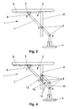
- FIG. 2 now shows a further particular embodiment of the lifting and lowering device 2 of a transport vehicle 1.
- a guide element 7 is movably and rotatably guided via a guide device 5.
- this guide element 7 is here connected to two hinged frames 10, 11 which in this example each form a parallelogram, each with two parallel sides, or is itself part of one of these hinged frames 10, 11.
- the construction elements are again always Y-shaped.
- Each of the two hinge frames 10, 11 here consists of two longer rods 13 and two shorter rods 12, 14, 15, or of something rod-like, as construction elements, which must of course each have the same length in order to form a parallelogram.
- a first hinge frame 10 is connected via a rod 15 at the two articulation points A with the receiving device 4 and the rod 15 is formed by the receiving device 4 itself.
- two further rods 13 are rotatably supported by joints 9, which in turn are connected to each other at the opposite side by a connecting element 12 to which the two rods 13 are in turn rotatably mounted.
- a connecting element 12 forms a part of the guide element 7, in particular the part between the connection point V and the connection with the receiving device 4, one of the two rods 13.
- the second parallelogram is formed by a structural element 14, which is designed here as part of the movement unit 3 and which again two rods 13 are rotatably mounted, which in turn are hingedly connected at the opposite end of the rods via the connecting element 12.
- the guide element 7 has twice the length as the rods 13 and the connection point V lies again in the middle of the guide element 7. From the kinematics of this arrangement, it follows that the receiving device 4 moves of the guide point F in turn is moved only vertically and that, due to the two hinge frame 10, 11, in addition, the receiving device 4 in all stroke positions their predetermined, here horizontal position retains. If the length ratios of the individual construction elements 7, 13 of the joint frame 10, 11 and the position of the connection point V chosen differently, as already described, there may be no pure vertical movement of the articulation point A more.
- the maximum achievable lifting height given by the length of the guide element 7, wherein the actual stroke range e.g. by the range of motion of the guide point F, by a linear actuator or can be specified or adjusted by prevailing space conditions.
- a guide device 5 in addition to the guide device 5 also a provide additional auxiliary guide.
- the pivot point A in an additional vertical auxiliary guide or the connection point V in an additional circular Auxiliary guide are led to increase the accuracy.
- Such an aide would However, do not change the kinematics of the lifting or lowering device 2 and would be for the Function of the lifting or lowering device 2 is not absolutely necessary and is therefore in the sense
- the invention should not be construed as a guide device 5, which is essentially the kinematic Ratios of the lifting and lowering device 2 determined.
- the lifting or lowering device 2 again consists of two construction elements 7, 8, wherein here one is designed as a rod 7 and the other as a vertical guide means 8.
- the rod 7 is movably guided with one end F in a horizontal guide device 5 and rotatably supported and movably guided with a further point V, between the two ends of the rod 7 in the vertical guide device 8 and rotatably supported.
- Both guide devices 5, 8 are arranged on the movement unit 3.
- the two construction elements 7, 8 of the lifting and lowering device 2 are in the lowest lifting position of the receiving device 4, so when the point V has reached the lower end of the guide device 8, in turn arranged clearly Y-shaped.
- the construction elements 7, 8 are interpreted as Y-arranged, since the unused end of the guide means 8 in these positions without lifting function. It can be easily deduced from the kinematics that the articulation point A would move along an elliptical path during a lifting movement here.
- the guide device 5 and / or the guide device 8 could of course again reach a substantially vertical movement of the receiving device 4.
- the pivot point A and the connection point V coincide in one point, so lead directly to the pivot point A in the vertical guide 8, so you would very easily achieve a vertical movement of the receiving device 4.
- the vertical guide device 8 could, for example, also be telescopic, ie, the guide device 8 is extended more or less far, depending on the stroke position.
- the transport vehicle 1 according to FIG. 3 is shown in FIG. 4 again with a parallelogram Articulated frame 10 equipped.
- the hinge frame 10 is again made of four construction elements 13, 14, 15, here rods, the joints over 9 to a parallelogram with each other are connected.
- One of the rods 13 is formed by a part of the guide element 7.
- This guide element 7 is arranged in the guide point F in a linear horizontal Guide device 5 guided movably and rotatably mounted.
- At the connection point V are the hinge frame 10 and the guide member 7 hinged together.
- connection point V and another point of the hinge frame 10 in a second linear vertically arranged as a guide device 8 formed Design element of the lifting and lowering device 2 guided movable and rotatable stored.
- this articulated frame 10 achieves that the receiving device 4 can be raised and lowered without pivoting.
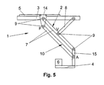
- the hinge frame 10 of the lifting and lowering device 2 could be guided in a guide device 5, as shown in Fig. 5.
- a construction element 14 is guided guided in a guide device 5.
- two rods 7 are rotatably supported by joints 9, which are connected at their opposite ends via a further rod-shaped construction element 15.
- the construction elements 7, 14, 15 thus again form a parallelogram-shaped hinge frame 10.
- a receiving device 4 is arranged with a load 6, wherein the structural element 15 could of course also be part of the receiving device 4.
- Another rod-shaped construction element 8 is connected at one end to the movement unit 3 and at the other end at the connection point V with a rod 7 of the hinge frame 10.
- this embodiment represents a further development of the lifting and lowering device of FIG. 1 and it is thus achieved in particular that the predetermined position of the receiving device 4, here the horizontal, is maintained in each stroke position. Otherwise, the same already said for Fig. 1 applies analogously.
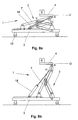
- a transport vehicle 1 as a vehicle of a monorail system is shown in Fig. 6.
- the movement unit 3 wheels or rollers 17 which are mounted movably on a guide rail 16 and thus the transport vehicle 1 along a transport path 20 which is predetermined by the guide rail 16, can be moved.
- a well-known drive such as towed or self-propelled, required, which is not shown in Fig. 6, however.
- the transport vehicles 1 hang mostly on the ceiling and are transported freely hanging over the ground. 6a now shows the transport vehicle 1 with the receiving device 4 in an upper end position O, ie the lifting or lowering device 2 is fully retracted and the receiving device 4 has reached its highest position.
- FIG. 6b A lower end position U of the receiving device 4 is shown by way of example in FIG. 6b.
- the transport vehicle 1 is here, for example, in a workstation 21, such as a welding station, and the receiving device 4 has been lowered to the component 6 in the workstation 21, if necessary, for processing, set down.
- a lifting drive 18 is provided in this example on the moving unit 3, which is connected via a cable or a chain with the receiving device 4.
- the lifting drive 18 engages here directly on the receiving device 4 at the Hubangriffstician H, which means that the weight of the load 6 is taken for the most part from the lifting drive 18 and the lifting and lowering device 2 plays only a guiding function, but not for the transmission of forces . If the lifting drive 18 would not act on the receiving device 4, but on a structural element of the lifting and lowering device 2, the design elements of the lifting and lowering device 2 would have to absorb and transmit the weight of the load 6 and the resulting bending moments. For this, however, the construction elements would have to be dimensioned accordingly, which would increase the weight and space requirements of the lifting and lowering device 2 undesirably.
- the lifting drive 18 should therefore attack in the vicinity of the receiving device 4 in this case, so that the load on the lifting and lowering device 2 is minimized and the lifting and lowering device 2 can be dimensioned as light and compact as possible.
- the Hubangriffstician H of the lifting drive 18 should not be more than 50% of the total length of the associated with the receiving device 4 structural element, preferably 15% or 25%, be removed from the pivot point A of the receiving device 4.
- FIG. 7 shows a variant in which the lifting and lowering device. 2 was extended with a conventional, known scissors mechanism 22. It is towards the load 6, a Y-shaped part 23 of the lifting and lowering device 2, whereby the advantages of Y-shaped arrangement remain, and to the moving unit 3 through the scissor mechanism 22 is provided.
- the kinematics of the lifting and lowering device 2 can by the design and connection of the construction elements and the guide device 5, As detailed above, are very easily influenced.
- a ground-guided transport vehicle 1 is shown in Fig. 8.
- the movement unit 3 in turn wheels or rollers 17, or the like, by means of which the transport vehicle 1 can be moved on the ground. This could be on the ground too be provided well-known management or control systems to the transport vehicle 1 to move along a path.
- a component 6 can here again from a lower end position U, Fig. 8a, in an upper end position O, Fig. 8b, are brought.
- Naturally All liners are possible.
- a lifting drive 18 here is a pneumatic or Hydraulic cylinder provided on the moving unit 3, whose movable piston on Hubangriffsige H on a structural element of the lifting or lowering device. 2 attacks.
- the Hubangriffstician H is in the vicinity of the pivot point A of the receiving device 4, ie in a range of 0 to 50% of the length of the structural element 7 at which the Hubangriffddling H is arranged.
- a transport vehicle 1 according to the invention could also be equipped with more than one lifting or lowering device 2. It would be conceivable, for example, in the direction of travel of the transport vehicle 1 on each side to provide one or more lifting or lowering device 2. In the same way it would also be conceivable to design the lifting or lowering device 2 differently within the scope of the invention. For example, two viewed in the direction of travel adjacent bars 8, or two hinge frames 10 and 11 may be provided between which the guide member 7 is arranged. Such an embodiment would have the advantage that it would be torque-free due to the symmetrical arrangement of the construction elements substantially. But of course, all other possible kinematic embodiments are encompassed by this invention.
- a transport vehicle 1 as described above may e.g. in production lines of the automotive industry be used for the transport of bodies or body parts, e.g. when Monorail System.
- the transport vehicles 1 will be moved along a rail mounted on the ceiling, for which the moving unit 3 of the Transport vehicle 1 must be carried out accordingly.
- the receiving devices 4 are lowered with the components 6 for processing.
- the special kinematics of the lifting or lowering device 2 are the components 6 on the Receiving device 4 laterally freely accessible and therefore unhindered, e.g. from Welding robots are processed.
- Transport means centering devices, such. Guide pin or spigot, used. Due to the guided movement, preferably a purely vertical movement, can the receiving devices 4 and the components 6 easily and safely in the Sliding centering.
- centering devices such as Guide pin or spigot, used. Due to the guided movement, preferably a purely vertical movement, can the receiving devices 4 and the components 6 easily and safely in the Sliding centering.
- the folding mechanism of the lifting or lowering device 2 also has the advantage that in a simple way supply lines, such as electricity, water, compressed air, etc., of devices on the receiving device, e.g. Tensioning or welding equipment, can be guided along the construction elements, these being not specific must be protected because the construction elements are not due to the kinematics In the work area and the risk of damage to the lines is therefore low.
- supply lines such as electricity, water, compressed air, etc.
- guide means any well-known and therefore here not specifically described constructions are used, such. a cone, a Carriage or a roller, which are guided in a corresponding rail, or also a Gleitstangen Entry, slide guide, etc.
Claims (37)
- Installation de transport pour transporter des éléments de structure (6), de préférence des carrosseries de véhicule, entre une pluralité de postes (21), de préférence, des postes de fabrication, le long d'une piste de transport (20), le long de laquelle une pluralité d'éléments de structure (6) peuvent être transportés, à l'aide d'une pluralité de véhicules de transport (1), les véhicules de transport (1) présentant au moins une unité de déplacement (3), au moins un dispositif support (4) pour supporter les éléments de structure (6) et au moins un dispositif de levage, respectivement d'abaissement (2) pour lever et/ou abaisser le dispositif support (4), dispositif de levage, respectivement d'abaissement (2) formé d'au moins un entraínement de levage (18) et d'une pluralité d'éléments de construction (7, 8), de préférence, allongés, pratiquement rigides, reliés ensemble par au moins une première articulation (9), sachant qu'au moins un premier et un deuxième élément de construction (7, 8) du dispositif de levage, respectivement d'abaissement (2), sont disposés en forme de Y en au moins une position de levage, caractérisée en ce que chaque fois une première extrémité de ces deux éléments de construction (7, 8) est reliée, par une deuxième et une troisième articulation (9), à l'unité de déplacement (3), en ce que la deuxième extrémité du premier élément de construction (7) est reliée au dispositif support (4), par une quatrième articulation (9), et en ce que la deuxième extrémité du deuxième élément de construction (8) est montée à rotation, entre les deux extrémités du premier élément de construction (7), sur celui-ci, par la première articulation (9), et en ce que la première extrémité d'un des deux éléments de construction (7, 8) est disposée de façon déplaçable, pouvant tourner, en étant guidée, dans un dispositif de guidage (5), et en ce que le point d'action de levage (H) de l'entraínement de levage (18) est disposé sur le dispositif support (4), ou à proximité d'un point d'articulation (A) du dispositif support (4), sur un élément de construction (7, 8), relié au dispositif support (4), de préférence dans la plage de 0 à 50 %, de préférence dans la plage de 0 à 25 % de la longueur de l'élément de construction le plus long, relié au dispositif support (4).
- Installation de transport selon la revendication 1, caractérisée en ce que la première extrémité du premier élément de construction (7) est disposée, de façon déplaçable et en pouvant tourner, dans le dispositif de guidage (5).
- Installation de transport selon la revendication 1 ou 2, caractérisée en ce que l'un des éléments de construction (7, 8) est plus long que l'autre élément de construction.
- Installation de transport selon la revendication 3, caractérisée en ce que l'élément de construction long présente sensiblement une longueur double celle de l'élément de construction court.
- Installation de transport selon la revendication 3 ou 4, caractérisée en ce que l'élément de construction court est relié de façon articulée, sensiblement au centre de l'élément de construction long, à l'élément de construction long.
- Installation de transport selon l'une des revendications 3 à 5, caractérisée en ce que le premier élément de construction (7) est l'élément de construction long.
- Installation de transport selon l'une des revendications 1 à 6, caractérisée en ce que le dispositif de guidage (5) est réalisé de manière que l'extrémité, reliée au dispositif support (4), du premier élément de construction (7) soit déplaçable sensiblement verticalement, au moyen de la cinématique du dispositif de levage, respectivement d'abaissement (2).
- Installation de transport selon la revendication 1, caractérisée en ce que le dispositif de levage, respectivement d'abaissement (2), est réalisé avec au moins un cadre d'articulation (10, 11) en plusieurs éléments, composé d'une pluralité d'éléments de construction (12, 13), reliés de façon articulée, et du premier élément de construction (7).
- Installation de transport selon la revendication 8, caractérisée en ce qu'au moins un, de préférence chacun des cadres articulés (10, 11) en plusieurs parties, est réalisé sous forme de parallélogramme, formé de quatre éléments de construction (12, 13, 14, 15) reliés ensemble de façon articulée, dont chaque fois deux éléments de construction (13, 12 et 15, 12 et 14) sont disposés sensiblement parallèles dans toutes les positions.
- Installation de transport selon la revendication 8 ou 9, caractérisée en ce qu'un élément de construction d'un premier cadre articulé forme simultanément également un élément de construction d'un deuxième cadre articulé et cet élément de liaison (12) forme la liaison entre les deux cadres articulés (10, 11).
- Installation de transport selon la revendication 10, caractérisée en ce qu'un élément de construction (14) d'un cadre articulé (10, 11) est relié rigidement à l'unité de déplacement (3) et, respectivement, est formé par l'unité de déplacement (3) et, sur cet élément de construction (14), les extrémités de deux autres éléments de construction (13) sont montés à rotation, sachant que les deux autres extrémités de ces éléments de construction (13) sont disposés et montés à rotation sur l'élément de liaison (12), et ces quatre éléments de construction (12, 13, 14) forment un premier cadre articulé (11).1
- Installation de transport selon la revendication 10 ou 11, caractérisée en ce qu'un élément de construction (15) d'un cadre articulé (10, 11) est relié rigidement au dispositif support (4), respectivement est formé par le dispositif support (4), et, sur cet élément de construction (15), les extrémité de deux autres éléments de construction (13) sont disposés en étant montés à rotation, sachant que les deux autres extrémités de ces éléments de construction (13) sont montés à rotation sur l'élément de liaison (12) et ces quatre éléments de construction (12, 13, 15) forment un deuxième cadre articulé (10).
- Installation de transport selon l'une des revendications 8 à 12, caractérisée en ce que la première extrémité du premier élément de construction (7) est disposée, de façon déplaçable de façon guidée et de façon pouvant tourner, dans le dispositif de guidage (5) et l'autre extrémité du premier élément de construction (7) est reliée à un élément de construction (12, 13) d'un cadre articulé (10, 11), respectivement est reliée au dispositif support (4).
- Installation de transport selon la revendication 13, caractérisée en ce que le premier élément de construction (7) est simultanément au moins partiellement un élément de construction (13) d'un cadre articulé (10, 11).
- Installation de transport selon l'une des revendications 8 à 14, caractérisée en ce que le premier élément de construction (9) est plus long que l'élément de construction le plus long des deux cadres articulés (10, 11).
- Installation de transport selon la revendication 15, caractérisée en ce que le premier élément de construction (7) est deux fois de la longueur de l'élément de construction le plus long du cadre articulé (10, 11).
- Installation de transport selon l'une des revendications 14 à 16, caractérisée en ce qu'une extrémité de l'élément de liaison (12) est disposée de façon à tourner entre les deux extrémités du premier élément de construction (7), sur le premier élément de construction (7).
- Installation de transport selon la revendication 17, caractérisée en ce qu'une extrémité de l'élément de liaison (12) est disposée de façon à pouvoir tourner entre les deux extrémités, sensiblement au centre du premier élément de construction (7), sur le premier élément dé construction (7).
- Installation de transport selon l'une des revendications 1 à 18, caractérisée en ce que les éléments de construction (13, 14, 15), l'élément de liaison (12) et/ou le premier élément de construction (7) sont réalisés au moins partiellement sous forme de barres, formées, de préférence, à partir de tubes, de tubes de forme ou de profilés.
- Installation de transport selon la revendication 1, caractérisée en ce qu'au moins une première partie du dispositif de levage et d'abaissement (2) est réalisée sous la forme de mécanisme à ciseau (22) en forme de X, connu depuis longtemps, et, à celui-ci, se raccorde une deuxième partie (23) en forme de Y, construite à partir d'un premier et d'un deuxième élément de construction (7, 8), du dispositif de levage et d'abaissement (2), sachant qu'au moins un élément de construction, de préférence un éléments de construction du mécanisme à ciseau en forme de X (22), du dispositif de levage et d'abaissement (2), est monté de façon à pouvoir se déplacer en étant guidé dans un dispositif de guidage (5).
- Installation de transport selon la revendication 20, caractérisée en ce qu'une pluralité d'éléments de construction sont réalisés sous la forme de cadres articulés en forme de parallélogramme.
- Installation de transport selon la revendication 21, caractérisée en ce qu'un cadre articulé est relié au dispositif support (4).
- Installation de transport selon la revendication 21 ou 22, caractérisée en ce qu'un cadre articulé fait partie du mécanisme à ciseau en forme de X (22).
- Installation de transport pour transporter des éléments de structure (6), de préférence des carrosseries de véhicule, entre une pluralité de postes (21), de préférence, des postes de fabrication, le long d'une piste de transport (20), le long de laquelle une pluralité d'éléments de structure (6) peuvent être transportés, à l'aide d'une pluralité de véhicules de transport (1), les véhicules de transport (1) présentant au moins une unité de déplacement (3), au moins un dispositif support (4) pour supporter les éléments de structure (6) et au moins un dispositif de levage, respectivement d'abaissement (2) pour lever et/ou abaisser le dispositif support (4), dispositif de levage, respectivement d'abaissement (2) formé d'au moins un entraínement de levage (18) et d'une pluralité d'éléments de construction (7, 8), de préférence, allongés, pratiquement rigides, reliés ensemble par au moins une première articulation (9), sachant qu'au moins un premier et un deuxième élément de construction (7, 8) du dispositif de levage, respectivement d'abaissement (2), sont disposés en forme de Y en au moins une position de levage, caractérisé en ce que le deuxième élément de construction (8) du dispositif de levage, respectivement d'abaissement (2) est réalisé sous la forme de premier dispositif de guidage, dont une première extrémité est fixée rigidement à l'unité de déplacement (3), et dans lequel au moins un premier point (V), pouvant être prédéterminé, du premier élément de construction (7) est monté, de façon déplaçable de façon guidée et de façon à pouvoir tourner, entre les deux extrémités du premier dispositif de guidage (8), en ce qu'une première extrémité du premier élément de construction (7) est déplaçable de façon guidée et montée à rotation dans un deuxième dispositif de guidage (5), disposé sur l'unité de déplacement (3), et la deuxième extrémité du premier élément de construction (7) est reliée au dispositif support (4) par une deuxième articulation (9), et en ce que le point d'action de levage (H) de l'entraínement de levage (18) est disposé sur le dispositif support (4), ou à proximité d'un point d'articulation (A) du dispositif support (4), sur un élément de contact (7, 8) relié au dispositif support (4), de préférence, dans la plage de 0 à 50 %, en particulier dans la plage de 0 à 25 % de la longueur du plus long élément construction relié au dispositif support (4).
- Installation de transport selon la revendication 24, caractérisée en ce que le dispositif de levage, respectivement d'abaissement (2), est réalisé avec au moins un cadre articulé (10) en plusieurs éléments, formé d'une pluralité d'éléments de construction (13), reliés ensemble de façon articulée, et du premier élément de construction (7), le premier élément de construction (7) faisant, le cas échéant, partie du cadre articulé (10).
- Installation de transport selon la revendication 25, caractérisée en ce que le premier élément de construction (7) est relié de façon articulée au cadre articulé (10).
- Installation de transport selon la revendication 25 ou 26, caractérisée en ce que le cadre articulé (10) est relié au dispositif support (4).
- Installation de transport selon l'une des revendications 24 à 27, caractérisée en ce que le premier dispositif de guidage (8) est orienté sensiblement verticalement ou obliquement, et le deuxième dispositif de guidage (5) est orienté sensiblement horizontalement ou obliquement.
- Installation de transport selon l'une des revendications 1 à 28, caractérisée en ce que les dispositifs de guidage (5, 8) sont réalisés au moins partiellement sous forme de guidage linéaire.
- Installation de transport selon l'une des revendications 1 à 29, caractérisée en ce que l'unité de déplacement (3) est munie de dispositifs pour assurer le déplacement du véhicule de transport (1), par exemple des roues, des galets, des dispositifs d'entraínement, des unités de commande, etc.
- Installation de transport selon l'une des revendications 1 à 30, caractérisée en ce que l'entraínement de levage (18) est réalisé sous la forme d'entraínement à câble, d'entraínement à chaíne, d'entraínement à tige filetée, d'entraínement à crémaillère, de vérin hydraulique ou de vérin pneumatique
- Installation de transport selon l'une des revendications 1 à 31, caractérisée en ce qu'au moins un dispositif de levage et d'abaissement (2) est disposé des deux côtés du véhicule de transport (1) dans la direction de transport.
- Installation de transport selon l'une des revendications 1 à 32, caractérisée en ce que le véhicule de transport (1) est réalisé sous la forme d'une bande de suspension, de préférence d'une bande de suspension électrique, l'unité de déplacement (3) étant déplaçable à l'aide de dispositifs appropriés, tels que, par exemple, des galets, des roues, etc., sur un système de guidage (16) disposé au-dessus du sol.
- Installation de transport selon l'une des revendications 1 à 32, caractérisée en ce que le véhicule de transport (1) est réalisé sous la forme de véhicule évoluant au sol, par exemple d'une plate-forme coulissante, l'unité de déplacement (3) étant déplaçable au sol, de façon autonome ou sous l'effet d'une propulsion extérieure.
- Installation de transport selon l'une des revendications 1 à 34, caractérisée en ce que le dispositif support (4) ou l'élément de structure (6) est susceptible d'être transféré ou pris en charge en au moins un poste (21), en une position de transfert, par le dispositif de levage, respectivement d'abaissement (2), sachant qu'à la position de transfert et/ou sur le dispositif de support (4), respectivement sur l'élément de structure (6), est prévu au moins un dispositif de centrage, pour la détermination de position du dispositif support (4), respectivement de l'élément de structure (6), dans le poste (21).
- Installation de transport selon la revendication 35, caractérisée en ce que le dispositif support (4), respectivement l'élément de structure (6), est levable ou abaissable sensiblement verticalement, pour assurer le transfert ou la prise en charge, et le dispositif de centrage est orienté verticalement de manière correspondante.
- Installation de transport selon la revendication 35, caractérisée en ce que le dispositif support (4), respectivement l'élément de structure (6), est susceptible d'être levé ou abaissé, sensiblement obliquement ou selon une trajectoire courbe, pour assurer le transfert, respectivement la prise en charge, et le dispositif de centrage est orienté également selon une obliquité correspondante.
Priority Applications (3)
| Application Number | Priority Date | Filing Date | Title |
|---|---|---|---|
| EP03028343A EP1408000A3 (fr) | 2002-07-03 | 2002-11-20 | Chariot de voie suspendue |
| EP02025922A EP1340709B1 (fr) | 2002-07-03 | 2002-11-20 | Installation de transport pour transporter des éléments de structure |
| US10/610,545 US20040037687A1 (en) | 2002-07-03 | 2003-07-02 | Transport system for the transport of components |
Applications Claiming Priority (3)
| Application Number | Priority Date | Filing Date | Title |
|---|---|---|---|
| EP02014709 | 2002-07-03 | ||
| EP02014709A EP1378480A1 (fr) | 2002-07-03 | 2002-07-03 | Véhicule de transport pour transporter des éléments de structure |
| EP02025922A EP1340709B1 (fr) | 2002-07-03 | 2002-11-20 | Installation de transport pour transporter des éléments de structure |
Related Child Applications (1)
| Application Number | Title | Priority Date | Filing Date |
|---|---|---|---|
| EP03028343.6 Division-Into | 2003-12-10 |
Publications (2)
| Publication Number | Publication Date |
|---|---|
| EP1340709A1 EP1340709A1 (fr) | 2003-09-03 |
| EP1340709B1 true EP1340709B1 (fr) | 2005-04-06 |
Family
ID=27736045
Family Applications (2)
| Application Number | Title | Priority Date | Filing Date |
|---|---|---|---|
| EP03028343A Withdrawn EP1408000A3 (fr) | 2002-07-03 | 2002-11-20 | Chariot de voie suspendue |
| EP02025922A Expired - Lifetime EP1340709B1 (fr) | 2002-07-03 | 2002-11-20 | Installation de transport pour transporter des éléments de structure |
Family Applications Before (1)
| Application Number | Title | Priority Date | Filing Date |
|---|---|---|---|
| EP03028343A Withdrawn EP1408000A3 (fr) | 2002-07-03 | 2002-11-20 | Chariot de voie suspendue |
Country Status (2)
| Country | Link |
|---|---|
| US (1) | US20040037687A1 (fr) |
| EP (2) | EP1408000A3 (fr) |
Families Citing this family (8)
| Publication number | Priority date | Publication date | Assignee | Title |
|---|---|---|---|---|
| DE10257108B4 (de) * | 2002-12-05 | 2008-05-21 | Eisenmann Anlagenbau Gmbh & Co. Kg | Fahrbare Hubvorrichtung |
| ITMI20070429A1 (it) * | 2007-03-02 | 2008-09-03 | Geico Spa | Dispositivo di movimentazione atto a fare traslare immergere e ruotare le scocche di autoveicoli furgoni cabine per camions e contenitori di oggetti metallici vari in vasche di trattamento e successivamente ad estrarle |
| DE102010045014A1 (de) | 2010-09-10 | 2012-03-15 | Eisenmann Ag | Anlage zur Oberflächenbehandlung von Fahrzeugkarosserien |
| US20130084158A1 (en) * | 2011-10-03 | 2013-04-04 | Gregory Garrett Evans | Lifting system |
| US9630815B2 (en) | 2011-11-04 | 2017-04-25 | GM Global Technology Operations LLC | Movement system configured for moving a payload |
| US10106378B2 (en) | 2015-11-03 | 2018-10-23 | General Electric Company | System and method for lifting with load moving machine |
| US10662816B2 (en) | 2016-04-12 | 2020-05-26 | General Electric Company | System and method to move turbomachinery |
| CN115320481A (zh) * | 2022-08-24 | 2022-11-11 | 上海建工集团股份有限公司 | 一种预制混凝土线性构件起吊和运输集成驳运装置及方法 |
Family Cites Families (15)
| Publication number | Priority date | Publication date | Assignee | Title |
|---|---|---|---|---|
| US1035265A (en) * | 1912-05-04 | 1912-08-13 | Brown Hoisting Machinery Co | Hoisting and conveying machine. |
| US2766007A (en) * | 1951-08-14 | 1956-10-09 | Krilanovich Steve | Camera hoist |
| US2785807A (en) * | 1953-02-03 | 1957-03-19 | Joseph H Prowinsky | Straight line lift truck |
| US4734979A (en) * | 1985-12-25 | 1988-04-05 | Mazda Motor Corporation | Weighty object mounting systems |
| US4790441A (en) * | 1986-09-15 | 1988-12-13 | Hansen Anders B N | Displacement apparatus |
| DE3702108C2 (de) * | 1987-01-24 | 1994-06-01 | Laepple August Gmbh & Co | Motorgetriebene Vorrichtung zum Umsetzen von Werkstücken |
| DE58902062D1 (de) * | 1988-03-31 | 1992-09-24 | Kuka Schweissanlagen & Roboter | Montageeinrichtung zum automatischen fuegen von aggregaten von der unterseite her mit einer kfz-karosserie. |
| US5013203A (en) * | 1988-04-20 | 1991-05-07 | Nakanishi Metal Works Co., Ltd. | Electrically driven self-propelled truck and apparatus for changing course thereof |
| US5219261A (en) * | 1988-08-22 | 1993-06-15 | Barry Leonard D | Rotary loader and system |
| JPH03117532U (fr) * | 1990-03-16 | 1991-12-04 | ||
| DE19518618A1 (de) * | 1995-05-24 | 1996-11-28 | Loedige Foerdertechnik | Maschinelle Handhabungsvorrichtung mit einer Gabel |
| US6619904B1 (en) * | 1998-03-04 | 2003-09-16 | Leonard Dodge Barry | Container transfer crossover and system |
| DE19957468A1 (de) * | 1999-11-24 | 2001-06-13 | Mannesmann Ag | Hebevorrichtung mit einer Führung für Lasten |
| US6712230B2 (en) * | 2001-11-07 | 2004-03-30 | Transportes Continuos Interiores, S.A. | Perfected device to transport vehicles in assembly lines |
| US6557235B1 (en) * | 2002-03-06 | 2003-05-06 | The Regents Of The University Of Michigan | Bi-axial coplanar apparatus |
-
2002
- 2002-11-20 EP EP03028343A patent/EP1408000A3/fr not_active Withdrawn
- 2002-11-20 EP EP02025922A patent/EP1340709B1/fr not_active Expired - Lifetime
-
2003
- 2003-07-02 US US10/610,545 patent/US20040037687A1/en not_active Abandoned
Also Published As
| Publication number | Publication date |
|---|---|
| US20040037687A1 (en) | 2004-02-26 |
| EP1340709A1 (fr) | 2003-09-03 |
| EP1408000A2 (fr) | 2004-04-14 |
| EP1408000A3 (fr) | 2004-11-03 |
Similar Documents
| Publication | Publication Date | Title |
|---|---|---|
| EP2719653B1 (fr) | Table élévatrice motorisée réglable en hauteur en direction verticale, p. ex. destinée à être utilisée dans le domaine de la carrosserie dans le secteur des véhicules automobiles | |
| EP1240071B1 (fr) | Dispositif de levage dote de moyens de guidage des charges | |
| EP0501254B1 (fr) | Table élévatrice à ciseaux | |
| DE69927070T2 (de) | Lateraler Ausleger für bewegliche Arbeitshebebühne mit vertikalem Mast | |
| EP0671228A2 (fr) | Installation de transport pour pièces à usiner dans une presse | |
| DE102004018059A1 (de) | Transfereinrichtung und Transferverfahren | |
| EP1340709B1 (fr) | Installation de transport pour transporter des éléments de structure | |
| DE102018113196A1 (de) | Palettenroboter mit Schwenkhubantrieb | |
| EP1961691A2 (fr) | Appareil de transbordement | |
| EP0590123B1 (fr) | Mecanisme de roulement a ecartement variable | |
| DE102009025493B4 (de) | Vorrichtung zum Heben und Senken von Lastkörpern | |
| EP2010736A1 (fr) | Système de garage pour véhicules à moteur | |
| DE19851743A1 (de) | Positioniereinrichtung mit Gewichtsausgleich | |
| EP1378480A1 (fr) | Véhicule de transport pour transporter des éléments de structure | |
| EP1516779B1 (fr) | Dispositif de charge pour un véhicule et véhicule correspondant | |
| EP1948549A1 (fr) | Dispositif de levage | |
| AT502741B1 (de) | Lasthebevorrichtung | |
| DE102005024289A1 (de) | Scherenhubtisch | |
| DE3442940A1 (de) | Hebetisch | |
| AT402728B (de) | Vakuum-eingabegerät | |
| EP1447372A2 (fr) | Dispositif de levage d'un convoyeur suspendu | |
| AT411459B (de) | Hubantrieb | |
| DE2414764C3 (de) | Einrichtung zum Kurzkuppeln zweier Fahrwerke eines Schienenfahrzeugs mit Tragschnäbeln | |
| DE102005039945A1 (de) | Scherenhubtisch | |
| DE3447995A1 (de) | Manipulator fuer die bearbeitung, insbesondere umformung, von blechen mittels einer presse oder dergleichen |
Legal Events
| Date | Code | Title | Description |
|---|---|---|---|
| PUAI | Public reference made under article 153(3) epc to a published international application that has entered the european phase |
Free format text: ORIGINAL CODE: 0009012 |
|
| 17P | Request for examination filed |
Effective date: 20030318 |
|
| AK | Designated contracting states |
Kind code of ref document: A1 Designated state(s): AT BE BG CH CY CZ DE DK EE ES FI FR GB GR IE IT LI LU MC NL PT SE SK TR |
|
| AX | Request for extension of the european patent |
Extension state: AL LT LV MK RO SI |
|
| GRAP | Despatch of communication of intention to grant a patent |
Free format text: ORIGINAL CODE: EPIDOSNIGR1 |
|
| AKX | Designation fees paid |
Designated state(s): AT BE BG CH CY CZ DE DK EE ES FI FR GB GR IE IT LI LU MC NL PT SE SK TR |
|
| GRAS | Grant fee paid |
Free format text: ORIGINAL CODE: EPIDOSNIGR3 |
|
| GRAA | (expected) grant |
Free format text: ORIGINAL CODE: 0009210 |
|
| AK | Designated contracting states |
Kind code of ref document: B1 Designated state(s): AT BE BG CH CY CZ DE DK EE ES FI FR GB GR IE IT LI LU MC NL PT SE SK TR |
|
| PG25 | Lapsed in a contracting state [announced via postgrant information from national office to epo] |
Ref country code: EE Free format text: LAPSE BECAUSE OF FAILURE TO SUBMIT A TRANSLATION OF THE DESCRIPTION OR TO PAY THE FEE WITHIN THE PRESCRIBED TIME-LIMIT Effective date: 20050406 Ref country code: TR Free format text: LAPSE BECAUSE OF FAILURE TO SUBMIT A TRANSLATION OF THE DESCRIPTION OR TO PAY THE FEE WITHIN THE PRESCRIBED TIME-LIMIT Effective date: 20050406 Ref country code: IE Free format text: LAPSE BECAUSE OF FAILURE TO SUBMIT A TRANSLATION OF THE DESCRIPTION OR TO PAY THE FEE WITHIN THE PRESCRIBED TIME-LIMIT Effective date: 20050406 Ref country code: FI Free format text: LAPSE BECAUSE OF FAILURE TO SUBMIT A TRANSLATION OF THE DESCRIPTION OR TO PAY THE FEE WITHIN THE PRESCRIBED TIME-LIMIT Effective date: 20050406 |
|
| REG | Reference to a national code |
Ref country code: GB Ref legal event code: FG4D Free format text: NOT ENGLISH |
|
| REG | Reference to a national code |
Ref country code: CH Ref legal event code: EP |
|
| REG | Reference to a national code |
Ref country code: IE Ref legal event code: FG4D Free format text: LANGUAGE OF EP DOCUMENT: GERMAN |
|
| REF | Corresponds to: |
Ref document number: 50202706 Country of ref document: DE Date of ref document: 20050512 Kind code of ref document: P |
|
| PG25 | Lapsed in a contracting state [announced via postgrant information from national office to epo] |
Ref country code: BG Free format text: LAPSE BECAUSE OF FAILURE TO SUBMIT A TRANSLATION OF THE DESCRIPTION OR TO PAY THE FEE WITHIN THE PRESCRIBED TIME-LIMIT Effective date: 20050706 Ref country code: GR Free format text: LAPSE BECAUSE OF FAILURE TO SUBMIT A TRANSLATION OF THE DESCRIPTION OR TO PAY THE FEE WITHIN THE PRESCRIBED TIME-LIMIT Effective date: 20050706 Ref country code: DK Free format text: LAPSE BECAUSE OF FAILURE TO SUBMIT A TRANSLATION OF THE DESCRIPTION OR TO PAY THE FEE WITHIN THE PRESCRIBED TIME-LIMIT Effective date: 20050706 |
|
| REG | Reference to a national code |
Ref country code: SE Ref legal event code: TRGR |
|
| GBT | Gb: translation of ep patent filed (gb section 77(6)(a)/1977) |
Effective date: 20050708 |
|
| PG25 | Lapsed in a contracting state [announced via postgrant information from national office to epo] |
Ref country code: PT Free format text: LAPSE BECAUSE OF FAILURE TO SUBMIT A TRANSLATION OF THE DESCRIPTION OR TO PAY THE FEE WITHIN THE PRESCRIBED TIME-LIMIT Effective date: 20050908 |
|
| REG | Reference to a national code |
Ref country code: ES Ref legal event code: FG2A Ref document number: 2240641 Country of ref document: ES Kind code of ref document: T3 |
|
| PG25 | Lapsed in a contracting state [announced via postgrant information from national office to epo] |
Ref country code: CY Free format text: LAPSE BECAUSE OF FAILURE TO SUBMIT A TRANSLATION OF THE DESCRIPTION OR TO PAY THE FEE WITHIN THE PRESCRIBED TIME-LIMIT Effective date: 20051120 |
|
| PG25 | Lapsed in a contracting state [announced via postgrant information from national office to epo] |
Ref country code: MC Free format text: LAPSE BECAUSE OF NON-PAYMENT OF DUE FEES Effective date: 20051130 Ref country code: LU Free format text: LAPSE BECAUSE OF NON-PAYMENT OF DUE FEES Effective date: 20051130 |
|
| REG | Reference to a national code |
Ref country code: IE Ref legal event code: FD4D |
|
| PLBE | No opposition filed within time limit |
Free format text: ORIGINAL CODE: 0009261 |
|
| STAA | Information on the status of an ep patent application or granted ep patent |
Free format text: STATUS: NO OPPOSITION FILED WITHIN TIME LIMIT |
|
| ET | Fr: translation filed | ||
| 26N | No opposition filed |
Effective date: 20060110 |
|
| REG | Reference to a national code |
Ref country code: GB Ref legal event code: 732E |
|
| NLT1 | Nl: modifications of names registered in virtue of documents presented to the patent office pursuant to art. 16 a, paragraph 1 |
Owner name: TMS TECHNIK-MASCHINENBAU-SYSTEME GMBH |
|
| NLS | Nl: assignments of ep-patents |
Owner name: TMS TRANSPORT-UND MONTAGESYSTEME GMBH Effective date: 20060518 |
|
| PG25 | Lapsed in a contracting state [announced via postgrant information from national office to epo] |
Ref country code: LI Free format text: LAPSE BECAUSE OF NON-PAYMENT OF DUE FEES Effective date: 20061130 Ref country code: CH Free format text: LAPSE BECAUSE OF NON-PAYMENT OF DUE FEES Effective date: 20061130 |
|
| REG | Reference to a national code |
Ref country code: FR Ref legal event code: CD Ref country code: FR Ref legal event code: TP |
|
| REG | Reference to a national code |
Ref country code: CH Ref legal event code: PL |
|
| BECH | Be: change of holder |
Owner name: *TMS TRANSPORT- UND MONTAGESYSTEME G.M.B.H. Effective date: 20060425 |
|
| BECN | Be: change of holder's name |
Owner name: *TMS TRANSPORT- UND MONTAGESYSTEME G.M.B.H. Effective date: 20050406 |
|
| REG | Reference to a national code |
Ref country code: DE Ref legal event code: R082 Ref document number: 50202706 Country of ref document: DE Representative=s name: KOHLER SCHMID MOEBUS, DE |
|
| PGFP | Annual fee paid to national office [announced via postgrant information from national office to epo] |
Ref country code: SK Payment date: 20131119 Year of fee payment: 12 |
|
| PGFP | Annual fee paid to national office [announced via postgrant information from national office to epo] |
Ref country code: BE Payment date: 20131121 Year of fee payment: 12 Ref country code: NL Payment date: 20131121 Year of fee payment: 12 |
|
| REG | Reference to a national code |
Ref country code: DE Ref legal event code: R082 Ref document number: 50202706 Country of ref document: DE Representative=s name: KOHLER SCHMID MOEBUS, DE |
|
| REG | Reference to a national code |
Ref country code: DE Ref legal event code: R082 Ref document number: 50202706 Country of ref document: DE Representative=s name: KOHLER SCHMID MOEBUS, DE Effective date: 20140709 Ref country code: DE Ref legal event code: R081 Ref document number: 50202706 Country of ref document: DE Owner name: TMS TURNKEY MANUFACTURING SOLUTIONS GMBH, AT Free format text: FORMER OWNER: TMS TRANSPORT- UND MONTAGESYSTEME GMBH, LINZ, AT Effective date: 20140709 Ref country code: DE Ref legal event code: R082 Ref document number: 50202706 Country of ref document: DE Representative=s name: KOHLER SCHMID MOEBUS, DE Effective date: 20120719 Ref country code: DE Ref legal event code: R082 Ref document number: 50202706 Country of ref document: DE Representative=s name: KOHLER SCHMID MOEBUS PATENTANWAELTE PARTNERSCH, DE Effective date: 20140709 Ref country code: DE Ref legal event code: R082 Ref document number: 50202706 Country of ref document: DE Representative=s name: KOHLER SCHMID MOEBUS PATENTANWAELTE PARTNERSCH, DE Effective date: 20120719 |
|
| REG | Reference to a national code |
Ref country code: ES Ref legal event code: PC2A Owner name: TMS TURNKEY MANUFACTURING SOLUTIONS GMBH Effective date: 20140915 |
|
| REG | Reference to a national code |
Ref country code: FR Ref legal event code: CD Owner name: TMS TURNKEY MANUFACTURING SOLUTIONS GMBH, AT Effective date: 20141016 |
|
| REG | Reference to a national code |
Ref country code: AT Ref legal event code: HC Ref document number: 292600 Country of ref document: AT Kind code of ref document: T Owner name: TMS TURNKEY MANUFACTURING SOLUTIONS GMBH, AT Effective date: 20141002 |
|
| REG | Reference to a national code |
Ref country code: NL Ref legal event code: V1 Effective date: 20150601 |
|
| PG25 | Lapsed in a contracting state [announced via postgrant information from national office to epo] |
Ref country code: BE Free format text: LAPSE BECAUSE OF NON-PAYMENT OF DUE FEES Effective date: 20141130 |
|
| PG25 | Lapsed in a contracting state [announced via postgrant information from national office to epo] |
Ref country code: SK Free format text: LAPSE BECAUSE OF NON-PAYMENT OF DUE FEES Effective date: 20141120 |
|
| REG | Reference to a national code |
Ref country code: SK Ref legal event code: MM4A Ref document number: E 242 Country of ref document: SK Effective date: 20141120 |
|
| PG25 | Lapsed in a contracting state [announced via postgrant information from national office to epo] |
Ref country code: NL Free format text: LAPSE BECAUSE OF NON-PAYMENT OF DUE FEES Effective date: 20150601 |
|
| REG | Reference to a national code |
Ref country code: FR Ref legal event code: PLFP Year of fee payment: 14 |
|
| REG | Reference to a national code |
Ref country code: FR Ref legal event code: PLFP Year of fee payment: 15 |
|
| PGFP | Annual fee paid to national office [announced via postgrant information from national office to epo] |
Ref country code: FR Payment date: 20161118 Year of fee payment: 15 Ref country code: GB Payment date: 20161122 Year of fee payment: 15 |
|
| PGFP | Annual fee paid to national office [announced via postgrant information from national office to epo] |
Ref country code: IT Payment date: 20161123 Year of fee payment: 15 |
|
| GBPC | Gb: european patent ceased through non-payment of renewal fee |
Effective date: 20171120 |
|
| REG | Reference to a national code |
Ref country code: FR Ref legal event code: ST Effective date: 20180731 |
|
| PG25 | Lapsed in a contracting state [announced via postgrant information from national office to epo] |
Ref country code: FR Free format text: LAPSE BECAUSE OF NON-PAYMENT OF DUE FEES Effective date: 20171130 Ref country code: IT Free format text: LAPSE BECAUSE OF NON-PAYMENT OF DUE FEES Effective date: 20171120 |
|
| PG25 | Lapsed in a contracting state [announced via postgrant information from national office to epo] |
Ref country code: GB Free format text: LAPSE BECAUSE OF NON-PAYMENT OF DUE FEES Effective date: 20171120 |
|
| PGFP | Annual fee paid to national office [announced via postgrant information from national office to epo] |
Ref country code: CZ Payment date: 20181116 Year of fee payment: 17 Ref country code: DE Payment date: 20181121 Year of fee payment: 17 Ref country code: SE Payment date: 20181120 Year of fee payment: 17 Ref country code: AT Payment date: 20181128 Year of fee payment: 17 |
|
| PGFP | Annual fee paid to national office [announced via postgrant information from national office to epo] |
Ref country code: ES Payment date: 20181213 Year of fee payment: 17 |
|
| REG | Reference to a national code |
Ref country code: DE Ref legal event code: R119 Ref document number: 50202706 Country of ref document: DE |
|
| REG | Reference to a national code |
Ref country code: SE Ref legal event code: EUG |
|
| PG25 | Lapsed in a contracting state [announced via postgrant information from national office to epo] |
Ref country code: CZ Free format text: LAPSE BECAUSE OF NON-PAYMENT OF DUE FEES Effective date: 20191120 |
|
| REG | Reference to a national code |
Ref country code: AT Ref legal event code: MM01 Ref document number: 292600 Country of ref document: AT Kind code of ref document: T Effective date: 20191120 |
|
| PG25 | Lapsed in a contracting state [announced via postgrant information from national office to epo] |
Ref country code: SE Free format text: LAPSE BECAUSE OF NON-PAYMENT OF DUE FEES Effective date: 20191121 |
|
| PG25 | Lapsed in a contracting state [announced via postgrant information from national office to epo] |
Ref country code: DE Free format text: LAPSE BECAUSE OF NON-PAYMENT OF DUE FEES Effective date: 20200603 |
|
| PG25 | Lapsed in a contracting state [announced via postgrant information from national office to epo] |
Ref country code: AT Free format text: LAPSE BECAUSE OF NON-PAYMENT OF DUE FEES Effective date: 20191120 |
|
| REG | Reference to a national code |
Ref country code: ES Ref legal event code: FD2A Effective date: 20210528 |
|
| PG25 | Lapsed in a contracting state [announced via postgrant information from national office to epo] |
Ref country code: ES Free format text: LAPSE BECAUSE OF NON-PAYMENT OF DUE FEES Effective date: 20191121 |