EP1340709B1 - Transport unit for transporting structurial elements - Google Patents
Transport unit for transporting structurial elements Download PDFInfo
- Publication number
- EP1340709B1 EP1340709B1 EP02025922A EP02025922A EP1340709B1 EP 1340709 B1 EP1340709 B1 EP 1340709B1 EP 02025922 A EP02025922 A EP 02025922A EP 02025922 A EP02025922 A EP 02025922A EP 1340709 B1 EP1340709 B1 EP 1340709B1
- Authority
- EP
- European Patent Office
- Prior art keywords
- constructional
- transport system
- lifting
- constructional element
- transport
- Prior art date
- Legal status (The legal status is an assumption and is not a legal conclusion. Google has not performed a legal analysis and makes no representation as to the accuracy of the status listed.)
- Expired - Lifetime
Links
- 230000033001 locomotion Effects 0.000 claims description 35
- 230000007246 mechanism Effects 0.000 claims description 10
- 238000012546 transfer Methods 0.000 claims description 9
- 238000004519 manufacturing process Methods 0.000 claims description 6
- 238000010276 construction Methods 0.000 description 50
- 238000013461 design Methods 0.000 description 20
- 230000008901 benefit Effects 0.000 description 9
- 238000003466 welding Methods 0.000 description 6
- 238000012545 processing Methods 0.000 description 4
- 238000005452 bending Methods 0.000 description 3
- 238000006073 displacement reaction Methods 0.000 description 2
- 230000005540 biological transmission Effects 0.000 description 1
- 230000006835 compression Effects 0.000 description 1
- 238000007906 compression Methods 0.000 description 1
- 238000011161 development Methods 0.000 description 1
- 230000000694 effects Effects 0.000 description 1
- 230000005489 elastic deformation Effects 0.000 description 1
- 230000005611 electricity Effects 0.000 description 1
- 230000005484 gravity Effects 0.000 description 1
- 238000003754 machining Methods 0.000 description 1
- 239000000463 material Substances 0.000 description 1
- 238000000034 method Methods 0.000 description 1
- 238000009420 retrofitting Methods 0.000 description 1
- 238000004904 shortening Methods 0.000 description 1
- 230000008093 supporting effect Effects 0.000 description 1
- XLYOFNOQVPJJNP-UHFFFAOYSA-N water Substances O XLYOFNOQVPJJNP-UHFFFAOYSA-N 0.000 description 1
Images


Classifications
-
- B—PERFORMING OPERATIONS; TRANSPORTING
- B66—HOISTING; LIFTING; HAULING
- B66F—HOISTING, LIFTING, HAULING OR PUSHING, NOT OTHERWISE PROVIDED FOR, e.g. DEVICES WHICH APPLY A LIFTING OR PUSHING FORCE DIRECTLY TO THE SURFACE OF A LOAD
- B66F7/00—Lifting frames, e.g. for lifting vehicles; Platform lifts
- B66F7/06—Lifting frames, e.g. for lifting vehicles; Platform lifts with platforms supported by levers for vertical movement
- B66F7/0691—Asymmetric linkages, i.e. Y-configuration
-
- B—PERFORMING OPERATIONS; TRANSPORTING
- B62—LAND VEHICLES FOR TRAVELLING OTHERWISE THAN ON RAILS
- B62D—MOTOR VEHICLES; TRAILERS
- B62D65/00—Designing, manufacturing, e.g. assembling, facilitating disassembly, or structurally modifying motor vehicles or trailers, not otherwise provided for
- B62D65/02—Joining sub-units or components to, or positioning sub-units or components with respect to, body shell or other sub-units or components
- B62D65/18—Transportation, conveyor or haulage systems specially adapted for motor vehicle or trailer assembly lines
-
- B—PERFORMING OPERATIONS; TRANSPORTING
- B66—HOISTING; LIFTING; HAULING
- B66F—HOISTING, LIFTING, HAULING OR PUSHING, NOT OTHERWISE PROVIDED FOR, e.g. DEVICES WHICH APPLY A LIFTING OR PUSHING FORCE DIRECTLY TO THE SURFACE OF A LOAD
- B66F7/00—Lifting frames, e.g. for lifting vehicles; Platform lifts
- B66F7/02—Lifting frames, e.g. for lifting vehicles; Platform lifts with platforms suspended from ropes, cables, or chains or screws and movable along pillars
-
- B—PERFORMING OPERATIONS; TRANSPORTING
- B66—HOISTING; LIFTING; HAULING
- B66F—HOISTING, LIFTING, HAULING OR PUSHING, NOT OTHERWISE PROVIDED FOR, e.g. DEVICES WHICH APPLY A LIFTING OR PUSHING FORCE DIRECTLY TO THE SURFACE OF A LOAD
- B66F7/00—Lifting frames, e.g. for lifting vehicles; Platform lifts
- B66F7/06—Lifting frames, e.g. for lifting vehicles; Platform lifts with platforms supported by levers for vertical movement
- B66F7/0616—Suspended platforms, i.e. the load platform hangs from the base
Definitions
- the present invention relates to a transport system for the transport of components, preferably Vehicle bodies, between a plurality of stations, preferably Manufacturing stations, along a transport path, along with a plurality of Transport vehicles a plurality of components are transportable, wherein the transport vehicles at least one movement unit, at least one receiving device for receiving the components and at least one lifting or lowering device for lifting and / or Lowering the receiving device, consisting of at least one lifting drive and at least two substantially rigid, preferably elongated, structural elements, which are connected by at least one joint, at least a first and a second structural element of the lifting or lowering device at least are arranged in a stroke position Y-shaped.
- the transport vehicles at least one movement unit, at least one receiving device for receiving the components and at least one lifting or lowering device for lifting and / or Lowering the receiving device, consisting of at least one lifting drive and at least two substantially rigid, preferably elongated, structural elements, which are connected by at least one joint, at least a first and a second structural element of
- Transport vehicles with a lifting or lowering device for lifting and / or lowering the receiving device, which carries the components are known in various designs. Such transport vehicles often use so-called scissor mechanisms as lifting or lowering device. These are both on the ground driving, as well as a hanging table on a transport vehicle, which runs on a guided on the ceiling, rail system. From EP 1 106 563 A1, for example, such a transport vehicle is known, wherein the lifting or lowering device is designed as a cable shears mechanism that require expensive cable guides and sometimes considerable rope lengths. In addition, the stability against the unwanted lateral deflection of the receiving device is not sufficient in all cases. In addition, these transport vehicles require a platform of appropriate size for accessibility to transporting material for structural reasons.
- the subject invention has therefore set itself the task of a transport vehicle specify a transport system with a lifting or lowering device, the simple, easy and is compact and can be easily and inexpensively manufactured.
- each a first end of the two Construction elements connected by a second and third joint with the moving unit is, the second end of the first construction element by a fourth joint with the receiving device is connected, the second end of the second construction element between the two ends of the first construction element on this the first joint is rotatably mounted, the first end of one of the two construction elements Guided guided in a guide device and is rotatably arranged and that the Hubangriffstician the lifting drive on the receiving device or in the Near a pivot point of the receiving device at one with the receiving device connected construction element attacks.
- At least one structural element is guided in a guide device movably arranged, wherein the guide means arranged on the moving unit is, whereby the lifting movement can be achieved with very simple design means.
- An embodiment of a lifting and lowering device with a long and a short Construction element, wherein the longer is guided in the guide device is very simple and can be made very easily.
- the lifting or lowering device with two interconnected multi-link articulated frame and a guide element, wherein the hinge frame are preferably designed as a parallelogram
- the hinge frame are preferably designed as a parallelogram
- the receiving device retains its original position with respect to the horizontal in all lifting positions and is not pivoted by the lifting movement.
- a length ratio between the guide element and a structural element of the joint frame of 2: 1 and a hinged connection between the hinge frame and guide element in the middle of the guide element a purely vertical movement of the receiving device is also ensured.
- a particularly simple embodiment results when the lifting or lowering device with at least one multi-articulated frame, consisting of a number hingedly interconnected construction elements, and a guide element is executed, wherein preferably the guide member hinged to the hinge frame connected is.
- a hinge frame and a guide element is sufficient to achieve the desired guided stroke, this is just a second Guide device required, resulting in a particularly simple and inexpensive Construction results.
- the construction elements, the connecting element and / or the guide element be advantageous from standard components, such as pipes, mold tubes, or profiles, at least partially designed as rods, which greatly simplifies the construction.
- the guide means is a linear guide and on the moving unit what the design of the kinematics and the production of the lifting or Lowering device simplified.
- the achievable lifting height of the lifting or lowering device of the transport vehicle can be very be easily enlarged when the lifting or lowering device is constructed in two parts, one part being constructed as a scissors mechanism and the second part being Y-shaped Design elements is formed. This gives you the advantage of an extended Lifting height with the same length when retracted.
- the lifting drive can be used as a cable drive, chain drive, threaded rod drive, as required, Hydraulic cylinder or pneumatic cylinder be executed.
- At least one lifting and lowering device can be arranged.
- An inventive transport vehicle can be particularly advantageous in one Transport system for transporting components, preferably vehicle bodies, between a plurality of stations, preferably manufacturing stations, along a Transport route, along with a plurality of transport vehicles a plurality of components are transportable, use.
- Such a transport system can be designed as a monorail, preferably an electric monorail, and the transport vehicle as a monorail vehicle.
- the benefits can be used in their entirety. It is a good accessibility to the cargo from above required, this can be formed hook-shaped receiving device.
- the good accessibility for welding or assembly operations also results from the fact that according to the plant function in the assembly areas, the load is lowered and thus not stand in the way of a manipulator due to the kinematics of the construction elements of the lifting or lowering device. Only in the raised position it lies across the load, which is not a disadvantage, because in this position only transport tasks are performed. Especially when retrofitting the means of transport in existing halls, the resulting low height of great advantage.
- a low weight is of great importance. Due to the fact that in the hanging arrangement, a flexible traction means for providing the lifting force can be used, such as a rope, a belt or a chain on a winch or the like, this results in the possibility of a particularly compact and lightweight design.
- the receiving device or the component is advantageously transferred or accepted in a transfer position by the lifting or lowering device, wherein in the transfer position and / or on the receiving device or on the component for determining the position of the receiving device or the component in the station at least one centering device is provided.
- the position of the components in the station can already be determined by the lifting or lowering movement, whereby such a transport system can be performed very easily.
- the receiving device can be lifted or lowered with the component for transfer either vertically, or alternatively as needed also obliquely or curved.
- FIG. 1 a very simple embodiment of a transport vehicle 1 according to the invention is shown.
- the transport vehicle 1 consists essentially of a moving unit 3, which is usually equipped with well-known, not shown here devices for moving the transport vehicle 1, such as wheels, rollers, drives, control units, etc., a lifting and lowering device 2 and an attached receiving device 4 for receiving any components.
- the lifting and lowering device 2 consists in this particular example of two construction elements 7, 8, here rod-shaped, which are rotatably connected to each other via joints 9.
- the longer rod is designed here as a guide element 7, whose guide means 5 associated end in this guide means 5 guided is movably and rotatably mounted.
- This end of the guide element 7 is connected via a further joint 9 rotatably connected to an element of the guide means 5 and can therefore be moved exclusively along a predetermined by the guide means 5 curve, in this particular example, a linear guide.
- the opposite end of the guide element 7 is connected at the pivot point A with the receiving device 4.
- the short rod 8 of the lifting and lowering device 2 is rotatably supported at one end via a hinge 9 on the moving unit 3 and rotatably supported at the other end via a hinge 9 between the two ends of the guide member 7 on the guide member 7. In an elevated or lowered position, the construction elements are therefore always Y-shaped arranged here.
- the lengths of the rod 8 and the guide member 7 are selected in the example of FIG.
- the receiving device 4 is lifted or lowered substantially vertically in this arrangement with a displacement of the guide point F along the guide means 5 and there is no horizontal displacement of the receiving device 4, as indicated by the dashed line in FIG. 1 is indicated.
- the receiving device 4 In a rigid connection between guide element 7 and receiving device 4, only the receiving device 4 would pivot, a maximum of 90 °. This pivoting could either be taken for granted, or one could also provide some compensation for the location of the receiving device 4.
- a suitable device such as a stepper motor, balance weights, or the like, compensate, so always a desired location, eg a horizontal position, the receiving device. 4 is guaranteed.
- the receiving device 4 would of course align so that the center of gravity of the receiving device 4 including the component 6 comes to rest on a vertical line through the pivot point A. Assigning the component 6 on the receiving device 4 accordingly, so you can very easily force a horizontal position of the receiving device 4.
- the length ratios of the construction elements 7, 8 and the position of the connection point V could also be chosen differently, which may then result in no purely vertical movement of the articulation point A more.
- this superimposed horizontal movement could be compensated kinematically, for example, by a suitable design of the guide curve of the guide device 5.
- the design of such a kinematic system, such as known slide control belongs in the standard knowledge of a corresponding expert and it is therefore not discussed in more detail.
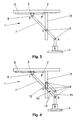
- FIG. 2 now shows a further particular embodiment of the lifting and lowering device 2 of a transport vehicle 1.
- a guide element 7 is movably and rotatably guided via a guide device 5.
- this guide element 7 is here connected to two hinged frames 10, 11 which in this example each form a parallelogram, each with two parallel sides, or is itself part of one of these hinged frames 10, 11.
- the construction elements are again always Y-shaped.
- Each of the two hinge frames 10, 11 here consists of two longer rods 13 and two shorter rods 12, 14, 15, or of something rod-like, as construction elements, which must of course each have the same length in order to form a parallelogram.
- a first hinge frame 10 is connected via a rod 15 at the two articulation points A with the receiving device 4 and the rod 15 is formed by the receiving device 4 itself.
- two further rods 13 are rotatably supported by joints 9, which in turn are connected to each other at the opposite side by a connecting element 12 to which the two rods 13 are in turn rotatably mounted.
- a connecting element 12 forms a part of the guide element 7, in particular the part between the connection point V and the connection with the receiving device 4, one of the two rods 13.
- the second parallelogram is formed by a structural element 14, which is designed here as part of the movement unit 3 and which again two rods 13 are rotatably mounted, which in turn are hingedly connected at the opposite end of the rods via the connecting element 12.
- the guide element 7 has twice the length as the rods 13 and the connection point V lies again in the middle of the guide element 7. From the kinematics of this arrangement, it follows that the receiving device 4 moves of the guide point F in turn is moved only vertically and that, due to the two hinge frame 10, 11, in addition, the receiving device 4 in all stroke positions their predetermined, here horizontal position retains. If the length ratios of the individual construction elements 7, 13 of the joint frame 10, 11 and the position of the connection point V chosen differently, as already described, there may be no pure vertical movement of the articulation point A more.
- the maximum achievable lifting height given by the length of the guide element 7, wherein the actual stroke range e.g. by the range of motion of the guide point F, by a linear actuator or can be specified or adjusted by prevailing space conditions.
- a guide device 5 in addition to the guide device 5 also a provide additional auxiliary guide.
- the pivot point A in an additional vertical auxiliary guide or the connection point V in an additional circular Auxiliary guide are led to increase the accuracy.
- Such an aide would However, do not change the kinematics of the lifting or lowering device 2 and would be for the Function of the lifting or lowering device 2 is not absolutely necessary and is therefore in the sense
- the invention should not be construed as a guide device 5, which is essentially the kinematic Ratios of the lifting and lowering device 2 determined.
- the lifting or lowering device 2 again consists of two construction elements 7, 8, wherein here one is designed as a rod 7 and the other as a vertical guide means 8.
- the rod 7 is movably guided with one end F in a horizontal guide device 5 and rotatably supported and movably guided with a further point V, between the two ends of the rod 7 in the vertical guide device 8 and rotatably supported.
- Both guide devices 5, 8 are arranged on the movement unit 3.
- the two construction elements 7, 8 of the lifting and lowering device 2 are in the lowest lifting position of the receiving device 4, so when the point V has reached the lower end of the guide device 8, in turn arranged clearly Y-shaped.
- the construction elements 7, 8 are interpreted as Y-arranged, since the unused end of the guide means 8 in these positions without lifting function. It can be easily deduced from the kinematics that the articulation point A would move along an elliptical path during a lifting movement here.
- the guide device 5 and / or the guide device 8 could of course again reach a substantially vertical movement of the receiving device 4.
- the pivot point A and the connection point V coincide in one point, so lead directly to the pivot point A in the vertical guide 8, so you would very easily achieve a vertical movement of the receiving device 4.
- the vertical guide device 8 could, for example, also be telescopic, ie, the guide device 8 is extended more or less far, depending on the stroke position.
- the transport vehicle 1 according to FIG. 3 is shown in FIG. 4 again with a parallelogram Articulated frame 10 equipped.
- the hinge frame 10 is again made of four construction elements 13, 14, 15, here rods, the joints over 9 to a parallelogram with each other are connected.
- One of the rods 13 is formed by a part of the guide element 7.
- This guide element 7 is arranged in the guide point F in a linear horizontal Guide device 5 guided movably and rotatably mounted.
- At the connection point V are the hinge frame 10 and the guide member 7 hinged together.
- connection point V and another point of the hinge frame 10 in a second linear vertically arranged as a guide device 8 formed Design element of the lifting and lowering device 2 guided movable and rotatable stored.
- this articulated frame 10 achieves that the receiving device 4 can be raised and lowered without pivoting.
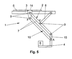
- the hinge frame 10 of the lifting and lowering device 2 could be guided in a guide device 5, as shown in Fig. 5.
- a construction element 14 is guided guided in a guide device 5.
- two rods 7 are rotatably supported by joints 9, which are connected at their opposite ends via a further rod-shaped construction element 15.
- the construction elements 7, 14, 15 thus again form a parallelogram-shaped hinge frame 10.
- a receiving device 4 is arranged with a load 6, wherein the structural element 15 could of course also be part of the receiving device 4.
- Another rod-shaped construction element 8 is connected at one end to the movement unit 3 and at the other end at the connection point V with a rod 7 of the hinge frame 10.
- this embodiment represents a further development of the lifting and lowering device of FIG. 1 and it is thus achieved in particular that the predetermined position of the receiving device 4, here the horizontal, is maintained in each stroke position. Otherwise, the same already said for Fig. 1 applies analogously.
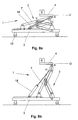
- a transport vehicle 1 as a vehicle of a monorail system is shown in Fig. 6.
- the movement unit 3 wheels or rollers 17 which are mounted movably on a guide rail 16 and thus the transport vehicle 1 along a transport path 20 which is predetermined by the guide rail 16, can be moved.
- a well-known drive such as towed or self-propelled, required, which is not shown in Fig. 6, however.
- the transport vehicles 1 hang mostly on the ceiling and are transported freely hanging over the ground. 6a now shows the transport vehicle 1 with the receiving device 4 in an upper end position O, ie the lifting or lowering device 2 is fully retracted and the receiving device 4 has reached its highest position.
- FIG. 6b A lower end position U of the receiving device 4 is shown by way of example in FIG. 6b.
- the transport vehicle 1 is here, for example, in a workstation 21, such as a welding station, and the receiving device 4 has been lowered to the component 6 in the workstation 21, if necessary, for processing, set down.
- a lifting drive 18 is provided in this example on the moving unit 3, which is connected via a cable or a chain with the receiving device 4.
- the lifting drive 18 engages here directly on the receiving device 4 at the Hubangriffstician H, which means that the weight of the load 6 is taken for the most part from the lifting drive 18 and the lifting and lowering device 2 plays only a guiding function, but not for the transmission of forces . If the lifting drive 18 would not act on the receiving device 4, but on a structural element of the lifting and lowering device 2, the design elements of the lifting and lowering device 2 would have to absorb and transmit the weight of the load 6 and the resulting bending moments. For this, however, the construction elements would have to be dimensioned accordingly, which would increase the weight and space requirements of the lifting and lowering device 2 undesirably.
- the lifting drive 18 should therefore attack in the vicinity of the receiving device 4 in this case, so that the load on the lifting and lowering device 2 is minimized and the lifting and lowering device 2 can be dimensioned as light and compact as possible.
- the Hubangriffstician H of the lifting drive 18 should not be more than 50% of the total length of the associated with the receiving device 4 structural element, preferably 15% or 25%, be removed from the pivot point A of the receiving device 4.
- FIG. 7 shows a variant in which the lifting and lowering device. 2 was extended with a conventional, known scissors mechanism 22. It is towards the load 6, a Y-shaped part 23 of the lifting and lowering device 2, whereby the advantages of Y-shaped arrangement remain, and to the moving unit 3 through the scissor mechanism 22 is provided.
- the kinematics of the lifting and lowering device 2 can by the design and connection of the construction elements and the guide device 5, As detailed above, are very easily influenced.
- a ground-guided transport vehicle 1 is shown in Fig. 8.
- the movement unit 3 in turn wheels or rollers 17, or the like, by means of which the transport vehicle 1 can be moved on the ground. This could be on the ground too be provided well-known management or control systems to the transport vehicle 1 to move along a path.
- a component 6 can here again from a lower end position U, Fig. 8a, in an upper end position O, Fig. 8b, are brought.
- Naturally All liners are possible.
- a lifting drive 18 here is a pneumatic or Hydraulic cylinder provided on the moving unit 3, whose movable piston on Hubangriffsige H on a structural element of the lifting or lowering device. 2 attacks.
- the Hubangriffstician H is in the vicinity of the pivot point A of the receiving device 4, ie in a range of 0 to 50% of the length of the structural element 7 at which the Hubangriffddling H is arranged.
- a transport vehicle 1 according to the invention could also be equipped with more than one lifting or lowering device 2. It would be conceivable, for example, in the direction of travel of the transport vehicle 1 on each side to provide one or more lifting or lowering device 2. In the same way it would also be conceivable to design the lifting or lowering device 2 differently within the scope of the invention. For example, two viewed in the direction of travel adjacent bars 8, or two hinge frames 10 and 11 may be provided between which the guide member 7 is arranged. Such an embodiment would have the advantage that it would be torque-free due to the symmetrical arrangement of the construction elements substantially. But of course, all other possible kinematic embodiments are encompassed by this invention.
- a transport vehicle 1 as described above may e.g. in production lines of the automotive industry be used for the transport of bodies or body parts, e.g. when Monorail System.
- the transport vehicles 1 will be moved along a rail mounted on the ceiling, for which the moving unit 3 of the Transport vehicle 1 must be carried out accordingly.
- the receiving devices 4 are lowered with the components 6 for processing.
- the special kinematics of the lifting or lowering device 2 are the components 6 on the Receiving device 4 laterally freely accessible and therefore unhindered, e.g. from Welding robots are processed.
- Transport means centering devices, such. Guide pin or spigot, used. Due to the guided movement, preferably a purely vertical movement, can the receiving devices 4 and the components 6 easily and safely in the Sliding centering.
- centering devices such as Guide pin or spigot, used. Due to the guided movement, preferably a purely vertical movement, can the receiving devices 4 and the components 6 easily and safely in the Sliding centering.
- the folding mechanism of the lifting or lowering device 2 also has the advantage that in a simple way supply lines, such as electricity, water, compressed air, etc., of devices on the receiving device, e.g. Tensioning or welding equipment, can be guided along the construction elements, these being not specific must be protected because the construction elements are not due to the kinematics In the work area and the risk of damage to the lines is therefore low.
- supply lines such as electricity, water, compressed air, etc.
- guide means any well-known and therefore here not specifically described constructions are used, such. a cone, a Carriage or a roller, which are guided in a corresponding rail, or also a Gleitstangen Entry, slide guide, etc.
Description
Die vorliegende Erfindung betrifft eine Transportanlage zum Transport von Bauteilen, vorzugsweise Fahrzeugkarosserien, zwischen einer Mehrzahl von Stationen, vorzugsweise Fertigungsstationen, entlang einer Transportstrecke, entlang der mit einer Mehrzahl von Transportfahrzeugen eine Mehrzahl von Bauteilen transportierbar sind, wobei die Transportfahrzeuge zumindest eine Bewegungseinheit, zumindest eine Aufnahmeeinrichtung zur Aufnahme der Bauteile und zumindest eine Heb- bzw. Senkeinrichtung zum Heben und/oder Senken der Aufnahmeeinrichtung, bestehend aus zumindest einem Hubantrieb und zumindest zwei im Wesentlichen starrer, vorzugsweise langgestreckter, Konstruktionselemente, die durch zumindest ein Gelenk miteinander verbunden sind, aufweisen, wobei zumindest ein erstes und ein zweites Konstruktionselement der Heb- bzw. Senkeinrichtung zumindest in einer Hubposition Y-förmig angeordnet sind.The present invention relates to a transport system for the transport of components, preferably Vehicle bodies, between a plurality of stations, preferably Manufacturing stations, along a transport path, along with a plurality of Transport vehicles a plurality of components are transportable, wherein the transport vehicles at least one movement unit, at least one receiving device for receiving the components and at least one lifting or lowering device for lifting and / or Lowering the receiving device, consisting of at least one lifting drive and at least two substantially rigid, preferably elongated, structural elements, which are connected by at least one joint, at least a first and a second structural element of the lifting or lowering device at least are arranged in a stroke position Y-shaped.
Transportfahrzeuge mit einer Heb- bzw. Senkeinrichtung zum Heben und/oder Senken der
Aufnahmeeinrichtung, die die Bauteile trägt sind in unterschiedlichsten Ausführungen bekannt.
Solche Transportfahrzeuge verwenden oftmals sogenannte Scherenmechanismen als Hub-
bzw. Senkeinrichtung. Diese gibt es sowohl am Boden fahrend, als auch als Hängetisch an
einem Transportfahrzeug, welches auf einem, an der Decke geführten, Schienensystem
läuft. Aus der EP 1 106 563 A1 ist beispielsweise ein solches Transportfahrzeug bekannt,
wobei die Heb- bzw. Senkeinrichtung als Seilscherenmechanismus ausgeführt ist, die
aufwendige Seilführungen und zum Teil erhebliche Seillängen benötigen. Darüber hinaus ist
die Stabilität gegenüber dem ungewollten seitlichen Ausweichen der Aufnahmeeinrichtung
nicht in allen Fällen ausreichend. Zusätzlich benötigen diese Transportfahrzeuge aus
konstruktiven Gründen eine Plattform mit entsprechender Größe die die Zugänglichkeit zum
Transportgut erschwert. Eine Ausführung eines solchen X-förmigen Scherenmechanismus
mit starren Elementen ist der US 5,013,203 A zu entnehmen. Eine solche Hebeinrichtung
weist jedoch eine große Baugröße auf, ist daher schwer und unhandlich.
Andere bekannte Transportfahrzeuge werden z.B. mit Teleskopsäulen, also mehrere
ineinander geschobene Teleskoparme, als Heb- bzw. Senkeinrichtungen ausgeführt, wie
z.B. aus der AT 399 306 B bekannt. Im eingefahrenen Zustand der Teleskopsäule ist eine
gewisse Mindestbauhöhe erforderlich, abhängig vom Hub und der Überdeckung der
Teleskoparme. Ist diese nicht akzeptabel, ist eine größere Anzahl von ausschiebbaren
Teleskoparmen erforderlich, was die Einrichtung verteuert. Aus Gründen der Zugänglichkeit
für entsprechende Bearbeitungen befindet sich die Last meistens seitlich neben der
Teleskopsäule und übt damit ein Biegemoment auf die Säule aus. Diese Lösung hat dadurch
den Nachteil, dass bei Be- und Entlastung das Ende des Teileträgers durch die Biegung der
vertikalen Säule und durch die unvermeidliche elastische Verformung der Bauteile nicht nur
unterschiedlich geneigt wird, sondern auch horizontal verschoben wird, wodurch eine exakte
Positionierung erschwert wird. Ähnliche Konstruktionen mit einer Hebeinrichtung mit säulenartigen
Elementen sind der US 5,088,176 A und der DE 195 18 618 A1 zu entnehmen.
Eine andere Möglichkeit zeigt die DE 199 57 468 A1, bei der ein Transportfahrzeug mit einer
Hebeeinrichtung angegeben wird, bei der mehrere schwenkbar verbundene Elemente in
Führungen geführt werden und während des Hebevorganges zusammen- oder auseinanderklappen
und somit der Bauteil gehoben bzw. gesenkt werden kann. Eine solche Vorrichtung
hat jedoch den Nachteil einer sehr komplexen, aufwendigen und damit teuren Kinematik und
Konstruktion.
Aus dem Stand der Technik sind auch weitere Heb- und Senkeinrichtungen bekannt. Z.B.
zeigen die US 2,766,007 und die US 2,785,807 je eine Heb- bzw. Senkeinrichtung mit Y-förmigen
Konstruktionselementen. Die Hubantriebe dieser Heb- bzw. Senkeinrichtungen
greifen allerdings so an den Konstruktionselementen an, dass ein Großteil der Gewichtskraft
der zu hebenden Last von den Konstruktionselementen der Heb- bzw. Senkeinrichtung
aufgenommen werden muss. Deshalb müssen die Konstruktionselemente der Heb- bzw.
Senkeinrichtung massiv dimensioniert werden, wodurch das Gesamtgewicht der Einheit
erheblich vergrößert wird. Für ein Transportfahrzeug einer Transportanlage, für das
möglichst geringe Eigengewichte gefordert werden, ist die Verwendung solcher Heb- bzw.
Senkeinrichtungen daher nicht erwünscht.Transport vehicles with a lifting or lowering device for lifting and / or lowering the receiving device, which carries the components are known in various designs.
Such transport vehicles often use so-called scissor mechanisms as lifting or lowering device. These are both on the ground driving, as well as a hanging table on a transport vehicle, which runs on a guided on the ceiling, rail system. From EP 1 106 563 A1, for example, such a transport vehicle is known, wherein the lifting or lowering device is designed as a cable shears mechanism that require expensive cable guides and sometimes considerable rope lengths. In addition, the stability against the unwanted lateral deflection of the receiving device is not sufficient in all cases. In addition, these transport vehicles require a platform of appropriate size for accessibility to transporting material for structural reasons. An embodiment of such an X-shaped scissors mechanism with rigid elements is shown in US 5,013,203 A. However, such a lifting device has a large size, is therefore heavy and unwieldy.
Other known transport vehicles, for example, with telescopic columns, that is, several telescoped telescopic arms, designed as lifting or lowering devices, such as from AT 399 306 B known. In the retracted state of the telescopic column a certain minimum height is required, depending on the hub and the coverage of the telescopic arms. If this is not acceptable, a larger number of telescopic telescopic arms is required, which makes the device more expensive. For reasons of accessibility for appropriate processing, the load is usually located laterally next to the telescopic column and thus exerts a bending moment on the column. This solution has the disadvantage that when loading and unloading the end of the parts carrier by the bending of the vertical column and by the inevitable elastic deformation of the components is not only differently inclined, but also moved horizontally, whereby an exact positioning is difficult. Similar constructions with a lifting device with columnar elements can be found in US 5,088,176 A and DE 195 18 618 A1.
Another possibility is shown in DE 199 57 468 A1, in which a transport vehicle is provided with a lifting device in which a plurality of pivotally connected elements are guided in guides and collapse or unfold during the lifting process and thus the component can be raised or lowered. However, such a device has the disadvantage of a very complex, expensive and therefore expensive kinematics and design.
From the prior art, other lifting and lowering devices are known. For example, US 2,766,007 and US 2,785,807 each show a lifting or lowering device with Y-shaped construction elements. However, the lifting drives of these lifting and lowering devices attack the structural elements such that a large part of the weight of the load to be lifted must be absorbed by the structural elements of the lifting or lowering device. Therefore, the construction elements of the lifting or lowering device must be massively dimensioned, whereby the total weight of the unit is considerably increased. For a transport vehicle of a transport system, for the lowest possible dead weights are required, the use of such lifting or lowering devices is therefore not desirable.
Die gegenständliche Erfindung hat sich deshalb die Aufgabe gestellt, ein Transportfahrzeug einer Transportanlage mit einer Hub- bzw. Senkeinrichtung anzugeben, das einfach, leicht und kompakt aufgebaut ist und einfach und kostengünstig hergestellt werden kann.The subject invention has therefore set itself the task of a transport vehicle specify a transport system with a lifting or lowering device, the simple, easy and is compact and can be easily and inexpensively manufactured.
Diese Aufgabe wird erfindungsgemäß dadurch gelöst, dass je ein erstes Ende der zwei Konstruktionselemente durch ein zweites und drittes Gelenk mit der Bewegungseinheit verbunden ist, das zweite Ende des ersten Konstruktionselements durch ein viertes Gelenk mit der Aufnahmeeinrichtung verbunden ist, das zweite Ende des zweiten Konstruktionselements zwischen den beiden Enden des ersten Konstruktionselements an diesem durch das erste Gelenk drehbar gelagert angeordnet ist, das erste Ende eines der zwei Konstruktionselemente in einer Führungseinrichtung geführt bewegbar und drehbar angeordnet ist und dass der Hubangriffspunkt des Hubantriebes an der Aufnahmeeinrichtung oder in der Nähe eines Anlenkpunktes der Aufnahmeeinrichtung an einem mit der Aufnahmeeinrichtung verbundenen Konstruktionselement angreift. This object is achieved in that each a first end of the two Construction elements connected by a second and third joint with the moving unit is, the second end of the first construction element by a fourth joint with the receiving device is connected, the second end of the second construction element between the two ends of the first construction element on this the first joint is rotatably mounted, the first end of one of the two construction elements Guided guided in a guide device and is rotatably arranged and that the Hubangriffspunkt the lifting drive on the receiving device or in the Near a pivot point of the receiving device at one with the receiving device connected construction element attacks.
Damit erzielt man zum Einen einen besonders einfachen und kompakten Aufbau des
Transportfahrzeuges. Durch die geringe erforderliche Anzahl an Konstruktionselementen
kann ein solches Transportfahrzeug auch sehr einfach und günstig hergestellt werden und
der zu transportierende Bauteil ist immer frei zugänglich, da in keiner Hubposition ein
Konstruktionselement den Zugang zum Bauteil versperrt.
Zum Anderen wird durch den besonderen Angriffspunkt des Hubantriebes sichergestellt,
dass ein Großteil der Gewichtskraft des Bauteils vom Hubantrieb aufgenommen wird und
nicht über die Konstruktionselemente der Heb- bzw. Senkeinrichtung aufgenommen und
übertragen werden muss. Die Heb- bzw. Senkeinrichtung muss somit nur mehr eine
Führungsfunktion erfüllen. Dadurch können die Konstruktionselemente sehr klein dimensioniert
werden, wodurch das Transportfahrzeug sehr leicht und kompakt wird.This achieves on the one hand a particularly simple and compact construction of the transport vehicle. Due to the low required number of construction elements, such a transport vehicle can also be made very easily and inexpensively and the component to be transported is always freely accessible, since in no lifting position a structural element obstructs access to the component.
On the other hand, it is ensured by the special point of application of the lifting drive that a large part of the weight of the component is absorbed by the lifting drive and does not have to be picked up and transmitted via the construction elements of the lifting or lowering device. The lifting or lowering device thus only has to fulfill a guiding function. As a result, the construction elements can be dimensioned very small, whereby the transport vehicle is very light and compact.
Vorteilhaft wird zumindest ein Konstruktionselement in einer Führungseinrichtung geführt bewegbar angeordnet, wobei die Führungseinrichtung an der Bewegungseinheit angeordnet ist, wodurch die Hubbewegung mit sehr einfachen konstruktiven Mitteln erzielt werden kann.Advantageously, at least one structural element is guided in a guide device movably arranged, wherein the guide means arranged on the moving unit is, whereby the lifting movement can be achieved with very simple design means.
Eine Ausführung einer Hub- und Senkeinrichtung mit einem langen und einem kurzen Konstruktionselement, wobei das längere in der Führungseinrichtung geführt wird ist besonders einfach aufgebaut und kann sehr einfach hergestellt werden. An embodiment of a lifting and lowering device with a long and a short Construction element, wherein the longer is guided in the guide device is very simple and can be made very easily.
Ist das lange Konstruktionselement das geführte und auch noch doppelt so lange wie das kurze und ist das kurze in der Mitte des langen gelenkig gelagert, ergibt sich eine ausgesprochen vorteilhafte Ausführung eines Transportfahrzeuges, da dann sichergestellt ist, dass die Aufnahmeeinrichtung rein vertikal bewegt wird, wodurch eine einfache Positionierung der Aufnahmeeinrichtung ermöglicht wird.Is the long construction element guided and also twice as long as that short and is the short articulated in the middle of the long, results in a pronounced advantageous embodiment of a transport vehicle, since then it is ensured that the receiving device is moved purely vertically, whereby easy positioning of the Recording device is enabled.
Bei beliebigen Längenverhältnissen der Konstruktionselemente ist es besonders vorteilhaft, die Führungseinrichtung derart auszuführen, dass durch die Kinematik der Heb- bzw. Senkeinrichtung das mit der Aufnahmeeinrichtung verbundene Ende des Führungselementes im Wesentlichen vertikal bewegt wird. Durch diese besondere Gestaltung der Führungseinrichtungen kann eine horizontale Bewegung der Aufnahmeeinrichtung ausgeglichen werden, wodurch wiederum eine einfache Positionierung der Aufnahmeeinrichtung ermöglicht wird.With any length ratios of the construction elements, it is particularly advantageous to perform the guide device such that by the kinematics of the lifting or Lowering device connected to the receiving device end of the guide element is moved substantially vertically. Due to this special design of the Guide means can be a horizontal movement of the receiving device be balanced, which in turn provides easy positioning of the receiving device is possible.
Bei einer Ausgestaltung der Hub- bzw. Senkeinrichtung mit zwei miteinander verbundenen
mehrgliedrigen Gelenkrahmen und einem Führungselement, wobei die Gelenkrahmen
vorzugsweise als Parallelogramm ausgeführt sind, ergeben sich ganz besondere Vorteile.
Aufgrund der Kinematik einer solchen Vorrichtung wird nämlich sichergestellt, dass die
Aufnahmeeinrichtung in allen Hebepositionen ihre ursprüngliche Lage bzgl. der Horizontalen
beibehält und durch die Hubbewegung nicht verschwenkt wird.
Bei einem Längenverhältnis zwischen Führungselement und einem Konstruktionselement
der Gelenkrahmen von 2:1 und einer gelenkigen Verbindung zwischen Gelenkrahmen und
Führungselement in der Mitte des Führungselementes wird außerdem eine rein vertikale
Bewegung der Aufnahmeeinrichtung gewährleistet.In one embodiment of the lifting or lowering device with two interconnected multi-link articulated frame and a guide element, wherein the hinge frame are preferably designed as a parallelogram, there are very special advantages. Because of the kinematics of such a device, it is ensured that the receiving device retains its original position with respect to the horizontal in all lifting positions and is not pivoted by the lifting movement.
With a length ratio between the guide element and a structural element of the joint frame of 2: 1 and a hinged connection between the hinge frame and guide element in the middle of the guide element, a purely vertical movement of the receiving device is also ensured.
Eine ganz besonders einfache Ausgestaltung ergibt sich, wenn die Heb- bzw. Senkeinrichtung mit zumindest einen mehrgliedrigen Gelenkrahmen, bestehend aus einer Anzahl gelenkig miteinander verbundener Konstruktionselemente, und einem Führungselement ausgeführt ist, wobei vorzugsweise das Führungselement gelenkig mit dem Gelenksrahmen verbunden ist. Bei dieser Ausgestaltung reicht ein Gelenkrahmen und ein Führungselement aus, um die erwünschte geführte Hubbewegung zu erzielen, dazu ist lediglich eine zweite Führungseinrichtung erforderlich, wodurch sich eine besonders einfache und günstige Konstruktion ergibt.A particularly simple embodiment results when the lifting or lowering device with at least one multi-articulated frame, consisting of a number hingedly interconnected construction elements, and a guide element is executed, wherein preferably the guide member hinged to the hinge frame connected is. In this embodiment, a hinge frame and a guide element is sufficient to achieve the desired guided stroke, this is just a second Guide device required, resulting in a particularly simple and inexpensive Construction results.
Die Konstruktionselemente, das Verbindungselement und/oder das Führungselement werden vorteilhaft aus Standardbauteilen, wie Rohren, Formrohren, oder Profilen, zumindest teilweise als Stäbe ausgeführt, was die Konstruktion wesentlich vereinfacht. The construction elements, the connecting element and / or the guide element be advantageous from standard components, such as pipes, mold tubes, or profiles, at least partially designed as rods, which greatly simplifies the construction.
Vorteilhaft ist die Führungseinrichtung eine lineare Führung und an der Bewegungseinheit angeordnet, was die Auslegung der Kinematik und die Herstellung der Hub- bzw. Senkeinrichtung vereinfacht.Advantageously, the guide means is a linear guide and on the moving unit what the design of the kinematics and the production of the lifting or Lowering device simplified.
Die erzielbare Hubhöhe der Heb- bzw. Senkeinrichtung des Transportfahrzeuges kann sehr einfach vergrößert werden, wenn die Heb- bzw. Senkeinrichtung zweiteilig aufgebaut wird, wobei ein Teil als Scherenmechanismus aufgebaut ist und der zweite Teil mit Y-förmigen Konstruktionselementen ausgebildet ist. Dadurch erhält man den Vorteil einer erweiterten Hubhöhe bei gleicher Baulänge im eingefahrenen Zustand.The achievable lifting height of the lifting or lowering device of the transport vehicle can be very be easily enlarged when the lifting or lowering device is constructed in two parts, one part being constructed as a scissors mechanism and the second part being Y-shaped Design elements is formed. This gives you the advantage of an extended Lifting height with the same length when retracted.
Der Hubantrieb kann je nach Bedarf als Seilantrieb, Kettenantrieb, Gewindestangenantrieb, Hydraulikzylinder oder Pneumatikzylinder ausgeführt sein.The lifting drive can be used as a cable drive, chain drive, threaded rod drive, as required, Hydraulic cylinder or pneumatic cylinder be executed.
In Fällen in denen besonders schwere Bauteile transportiert werden müssen, oder aus Platzgründen könnte in Transportrichtung zu beiden Seiten des Transportfahrzeuges zumindest je eine Hub- und Senkeinrichtung angeordnet sein.In cases where particularly heavy components have to be transported, or out Space reasons could in the transport direction to both sides of the transport vehicle at least one lifting and lowering device can be arranged.
Ein erfindungsgemäßes Transportfahrzeug lässt sich besonders vorteilhaft in einer Transportanlage zum Transport von Bauteilen, vorzugsweise Fahrzeugkarosserien, zwischen einer Mehrzahl von Stationen, vorzugsweise Fertigungsstationen, entlang einer Transportstrecke, entlang der mit einer Mehrzahl von Transportfahrzeugen eine Mehrzahl von Bauteilen transportierbar sind, einsetzen.An inventive transport vehicle can be particularly advantageous in one Transport system for transporting components, preferably vehicle bodies, between a plurality of stations, preferably manufacturing stations, along a Transport route, along with a plurality of transport vehicles a plurality of components are transportable, use.
Eine solche Transportanlage kann als Hängebahn, vorzugsweise eine Elektrohängebahn,
und das Transportfahrzeug als Hängebahnfahrzeug ausgeführt sein.
Bei einer solchen Anwendung können die Vorteile in ihrer Gesamtheit genutzt werden. Es
wird eine gute Zugänglichkeit an das Transportgut von oben gefordert, dazu kann die
Aufnahmeeinrichtung hakenförmig ausgebildet werden. Die gute Zugänglichkeit für Schweißoder
Montageoperationen ergibt sich auch dadurch, dass entsprechend der Anlagenfunktion
in den Montagebereichen die Last abgesenkt wird und damit aufgrund der Kinematik die
Konstruktionselemente der Hub- bzw. Senkeinrichtung einem Manipulator nicht im Weg
stehen. Lediglich in gehobener Stellung liegt sie quer über der Last, was keinen Nachteil
darstellt, weil in dieser Stellung nur Transportaufgaben durchgeführt werden. Besonders
beim nachträglichen Einbau des Transportmittels in bestehende Hallen ist die sich
ergebende geringe Bauhöhe von großem Vorteil.
Ebenso ist gerade bei Hängebahnen ein geringes Eigengewicht von großer Bedeutung.
Durch die Tatsache, dass bei der hängenden Anordnung ein flexibles Zugmittel zur
Erbringung der Hubkraft eingesetzt werden kann, beispielsweise ein Seil, ein Gurt oder eine
Kette an einer Winde oder ähnlichem, ergibt sich hier die Möglichkeit einer besonders
kompakten und leichten Ausführung.Such a transport system can be designed as a monorail, preferably an electric monorail, and the transport vehicle as a monorail vehicle.
In such an application, the benefits can be used in their entirety. It is a good accessibility to the cargo from above required, this can be formed hook-shaped receiving device. The good accessibility for welding or assembly operations also results from the fact that according to the plant function in the assembly areas, the load is lowered and thus not stand in the way of a manipulator due to the kinematics of the construction elements of the lifting or lowering device. Only in the raised position it lies across the load, which is not a disadvantage, because in this position only transport tasks are performed. Especially when retrofitting the means of transport in existing halls, the resulting low height of great advantage.
Likewise, especially with monorails a low weight is of great importance. Due to the fact that in the hanging arrangement, a flexible traction means for providing the lifting force can be used, such as a rope, a belt or a chain on a winch or the like, this results in the possibility of a particularly compact and lightweight design.
Eine weitere sehr günstige Anwendung ist eine bodengebundene Transportanlage mit einem bodengebundenen Transportfahrzeug, wobei sich im Wesentlichen die gleichen Vorteile wie oben ergeben.Another very cheap application is a ground-based transport system with a ground-based transport vehicle, with essentially the same advantages as above.
Um eine Positionsgenaue Bearbeitung in einer Station, z.B. eine Schweißstation, sicherzustellen,
ist die Aufnahmeeinrichtung bzw. der Bauteil vorteilhaft in einer Übergabeposition
durch die Heb- bzw. Senkeinrichtung übergeb- bzw. übernehmbar, wobei in der Übergabeposition
und/oder an der Aufnahmeeinrichtung bzw. am Bauteil zur Positionsbestimmung der
Aufnahmeeinrichtung bzw. des Bauteils in der Station zumindest eine Zentriereinrichtung
vorgesehen ist. Dadurch kann bereits durch die Hub- bzw. Senkbewegung die Position der
Bauteile in der Station bestimmt werden, wodurch eine solche Transportanlage sehr einfach
ausgeführt werden kann.
Dazu kann die Aufnahmeeinrichtung mit dem Bauteil zur Übergabe entweder vertikal, oder
alternativ je nach Bedarf auch schräg oder kurvenförmig gehoben oder gesenkt werden.In order to ensure position-accurate machining in a station, for example a welding station, the receiving device or the component is advantageously transferred or accepted in a transfer position by the lifting or lowering device, wherein in the transfer position and / or on the receiving device or on the component for determining the position of the receiving device or the component in the station at least one centering device is provided. As a result, the position of the components in the station can already be determined by the lifting or lowering movement, whereby such a transport system can be performed very easily.
For this purpose, the receiving device can be lifted or lowered with the component for transfer either vertically, or alternatively as needed also obliquely or curved.
Die gegenständliche Erfindung wird im folgenden anhand der beispielhaften, nicht einschränkenden,
spezielle Ausführungsbeispiele zeigenden Figuren 1 bis 6 beschrieben.
Dabei zeigt
In Fig. 1 ist eine sehr einfache Ausgestaltung eines erfindungsgemäßen Transportfahrzeuges
1 dargestellt. Das Transportfahrzeuges 1 besteht dabei im Wesentlichen aus einer
Bewegungseinheit 3, die in der Regel mit hinlänglich bekannten, hier nicht dargestellten
Einrichtungen zum Bewegen des Transportfahrzeuges 1, wie Räder, Rollen, Antriebe,
Steuereinheiten, etc., ausgestattet ist, einer Hub- und Senkeinrichtung 2 und einer daran
befestigten Aufnahmeeinrichtung 4 zur Aufnahme beliebiger Bauteile 6.
Die Hub- und Senkeinrichtung 2 besteht in diesem speziellen Beispiel aus zwei Konstruktionselementen
7, 8, hier stabförmig, die über Gelenke 9 drehbar miteinander verbunden
sind. Der längere Stab ist hier als Führungselement 7 ausgeführt, dessen einer
Führungseinrichtung 5 zugeordnetes Ende in dieser Führungseinrichtung 5 geführt
bewegbar und drehbar gelagert ist. Dieses Ende des Führungselementes 7 ist über ein
weiteres Gelenk 9 drehbar mit einem Element der Führungseinrichtung 5 verbunden und
kann daher ausschließlich entlang einer durch die Führungseinrichtung 5 vorgegebenen
Kurve bewegt werden, in diesem speziellen Beispiel eine lineare Führung. Das entgegengesetzte
Ende des Führungselementes 7 ist am Anlenkpunkt A mit der Aufnahmeeinrichtung
4 verbunden. Der kurze Stab 8 der Hub- und Senkeinrichtung 2 ist mit einem Ende über ein
Gelenk 9 an der Bewegungseinheit 3 drehbar gelagert und mit dem anderen Ende wiederum
über ein Gelenk 9 zwischen den beiden Enden des Führungselementes 7 am Führungselement
7 drehbar gelagert. In einer gehobenen bzw. gesenkten Position sind die
Konstruktionselemente hier also immer Y-förmig angeordnet.
Die Längen des Stabes 8 und des Führungselementes 7 sind im Beispiel nach Fig. 1 so
gewählt, dass das Führungselement 7 doppelt so lang ist, wie die Länge des kurzen Stabes
8 und der Verbindungspunkt V zwischen Führungselement 7 und dem kurzen Stab 8 ist in
der Mitte des Führungselementes 7 gewählt. Aus dieser speziellen Gestaltung ergeben sich
besondere kinematische Vorteile. Wie man sich kinematisch leicht überlegen kann, wird die
Aufnahmeeinrichtung 4 bei dieser Anordnung bei einer Verschiebung des Führungspunktes
F entlang der Führungseinrichtung 5 im Wesentlichen senkrecht gehoben oder abgesenkt
und es kommt zu keiner horizontalen Verschiebung der Aufnahmeeinrichtung 4, wie durch
die strichlierte Linie in Fig. 1 angedeutet wird.
Bei einer starren Verbindung zwischen Führungselement 7 und Aufnahmeeinrichtung 4
würde sich lediglich die Aufnahmeeinrichtung 4 verschwenken, maximal um 90°. Diese
Verschwenkung könnte man entweder als gegeben hinnehmen, oder man könnte auch einen
gewissen Ausgleich der Lage der Aufnahmeeinrichtung 4 vorsehen. Z.B. könnten man eine
drehbare Verbindung zwischen Führungselement 7 und Aufnahmeeinrichtung 4 am
Anlenkpunkt A vorsehen und die Verschwenkung durch eine geeignete Vorrichtung, wie z.B.
ein Schrittmotor, Balancegewichte, oder ähnliches, ausgleichen, sodass immer eine
erwünschte Lage, z.B. eine horizontale Lage, der Aufnahmeeinrichtung 4 gewährleistet ist.
Bei einer gelenkigen Verbindung zwischen Führungselement 7 und Aufnahmeeinrichtung 4,
wie in Fig. 1 dargestellt, würde sich die Aufnahmeeinrichtung 4 natürlich so ausrichten, dass
der Schwerpunkt der Aufnahmeeinrichtung 4 einschließlich dem Bauteil 6 auf einer senkrechten
Linie durch den Anlenkpunkt A zu liegen kommt. Ordnet man den Bauteil 6 auf der
Aufnahmeeinrichtung 4 entsprechend an, so kann man sehr einfach eine horizontale Lage
der Aufnahmeeinrichtung 4 erzwingen.
Natürlich könnten die Längenverhältnisse der Konstruktionselemente 7, 8 und die Lage des
Verbindungspunktes V auch anders gewählt werden, wobei sich dann unter Umständen
keine rein vertikale Bewegung des Anlenkpunktes A mehr ergibt. Diese überlagerte
horizontale Bewegung könnte man kinematisch jedoch z.B. durch eine geeignete Gestaltung
der Führungskurve der Führungseinrichtung 5 ausgleichen. Die Auslegung eines solchen
kinematischen Systems, wie z.B. bekannte Kulissensteuerung, gehört in das Standardwissen
eines entsprechenden Fachmannes und es wird daher nicht näher darauf eingegangen.
Ist hingegen das Ende des Stabes 8 an der Bewegungseinheit 3 in einer Führungseinrichtung
5 geführt und dafür das Führungselement 7 fest an der Bewegungseinrichtung 3
drehbar gelagert, dann ergäbe sich immer eine vertikale und horizontale Bewegung des
Anlenkpunktes A, hier natürlich eine kreisbogenförmige, die auch nicht ausgeglichen werden
könnte. Eine solche Anordnung wäre jedoch natürlich genauso denkbar.
Es wäre aber natürlich auch denkbar beide Stäbe 7, 8 in einer Führungseinrichtung 5 zu
führen.In Fig. 1, a very simple embodiment of a
The lifting and lowering
The lengths of the
In a rigid connection between
Of course, the length ratios of the
If, however, the end of the
Of course, it would also be conceivable to guide both
Würde man den Anlenkpunkt A mit dem Verbindungspunkt V zusammenfallen lassen, d.h.
die Last würde direkt an der Verbindung der beiden Stäbe 7, 8 angreifen, so würde sich eine
V-förmige Anordnung der Konstruktionselemente ergeben, die jedoch nur einen Extremfall
der Y-förmigen Anordnung darstellt und daher in den Begriff Y-förmig subsumiert werden
kann.If one were to let the pivot point A coincide with the connection point V, i.
the load would act directly on the connection of the two
Die Fig. 2 zeigt nun eine weitere besondere Ausgestaltung der Hub- und Senkeinrichtung 2
eines Transportfahrzeuges 1. Bei diesem Beispiel ist wiederum ein Ende eines Führungselementes
7 über eine Führungseinrichtung 5 geführt bewegbar und drehbar gelagert.
Dieses Führungselement 7 ist hier jedoch mit zwei Gelenkrahmen 10, 11 verbunden, die in
diesem Beispiel je ein Parallelogramm, mit jeweils zwei parallelen Seiten, bilden, bzw. ist
teilweise selbst Teil eines dieser Gelenkrahmen 10, 11. In einer gehobenen bzw. gesenkten
Position sind die Konstruktionselemente wieder immer Y-förmig angeordnet.
Jeder der beiden Gelenkrahmen 10, 11 besteht hier aus zwei längeren Stäben 13 und zwei
kürzeren Stäben 12, 14, 15, bzw. aus etwas stabähnlichem, als Konstruktionselemente, die
natürlich jeweils die gleiche Länge aufweisen müssen, um ein Parallelogramm bilden zu
können. Ein erster Gelenkrahmen 10 ist über einen Stab 15 an den beiden Anlenkpunkten A
mit der Aufnahmeeinrichtung 4 verbunden bzw. wird der Stab 15 von der Aufnahmeeinrichtung
4 selbst gebildet. An diesen Stab 15 sind über Gelenke 9 zwei weitere Stäbe 13
drehbar gelagert angeordnet, die an der gegenüberliegenden Seite wiederum durch ein
Verbindungselement 12, an dem die beiden Stäbe 13 wiederum drehbar gelagert sind,
miteinander verbunden sind. Dabei bildet ein Teil des Führungselementes 7, im speziellen
der Teil zwischen Verbindungspunkt V und der Verbindung mit der Aufnahmeeinrichtung 4,
einen der beiden Stäbe 13. Das zweite Parallelogramm wird durch ein Konstruktionselement
14 gebildet, das hier als Teil der Bewegungseinheit 3 ausgebildet ist und an dem wieder zwei
Stäbe 13 drehbar gelagert angeordnet sind, die am gegenüberliegenden Ende der Stäbe
wiederum über das Verbindungselement 12 gelenkig verbunden sind. Die beiden so, über
das Verbindungselement 12 verbundenen Gelenkrahmen 10, 11 sind über einen einzigen
Verbindungspunkt V gelenkig mit dem Führungselement 7 verbunden. Wie bei der
Ausführung nach Fig. 1 weist auch hier das Führungselement 7 die doppelte Länge wie die
Stäbe 13 auf und der Verbindungspunkt V liegt wieder in der Mitte des Führungselementes
7. Aus der Kinematik dieses Anordnung ergibt sich, dass die Aufnahmeeinrichtung 4 bei
einer Bewegung des Führungspunktes F wiederum ausschließlich vertikal bewegt wird und
dass, aufgrund der beiden Gelenkrahmen 10, 11, zusätzlich die Aufnahmeeinrichtung 4 in
allen Hubpositionen ihre vorgegebene, hier horizontale, Lage beibehält.
Werden die Längenverhältnisse der einzelnen Konstruktionselemente 7, 13 der Gelenkrahmen
10, 11 und die Lage des Verbindungspunktes V anders gewählt, ergibt sich, wie
bereits beschrieben, unter Umständen keine reine vertikale Bewegung des Anlenkpunktes A
mehr. Diese überlagerte horizontale Bewegung könnte man wieder kinematisch, z.B. durch
eine geeignete Gestaltung der Führungskurve der Führungseinrichtung 5, ausgleichen.
Gleichfalls wäre es auch hier denkbar, ein anderes oder mehrere Konstruktionselement(e) in
einer oder weiteren Führungseinrichtung(en) zu führen, wie oben bereits beschrieben.FIG. 2 now shows a further particular embodiment of the lifting and lowering
Each of the two hinge frames 10, 11 here consists of two
If the length ratios of the
Bei beiden oben beschriebenen Ausführungen wird die maximale erreichbare Hubhöhe
durch die Länge des Führungselementes 7 vorgegeben, wobei der tatsächliche Hubbereich
z.B. durch den Bewegungsspielraum des Führungspunktes F, durch einen Hubantrieb oder
durch vorherrschende Platzverhältnisse vorgegeben sein bzw. eingestellt werden kann.In both embodiments described above, the maximum achievable lifting height
given by the length of the
Selbstverständlich wäre es auch denkbar, neben der Führungseinrichtung 5 auch noch eine
weitere Hilfsführung vorzusehen. Z.B. könnte der Anlenkpunkt A in einer zusätzlichen
vertikalen Hilfsführung oder der Verbindungspunkt V in einer zusätzlichen kreisförmigen
Hilfsführung geführt werden, um die Genauigkeit zu erhöhen. Eine solche Hilfsführung würde
die Kinematik der Hub- bzw. Senkeinrichtung 2 jedoch nicht verändern und wäre für die
Funktion der Hub- bzw. Senkeinrichtung 2 nicht unbedingt erforderlich und ist daher im Sinne
der Erfindung nicht als Führungseinrichtung 5 aufzufassen, die wesentlich die kinematischen
Verhältnisse der Hub- bzw. Senkeinrichtung 2 bestimmt. Grundsätzlich könnte also jeder
beliebige Punkt eines beliebigen Konstruktionselementes in einer Führungseinrichtung
geführt werden, womit die Kinematik und die Funktion festgelegt wäre, wobei darüber hinaus
beliebige weitere zusätzliche Hilfsführungen vorgesehen werden könnten, die die Kinematik
jedoch nicht verändern würden, für die Funktion nicht unbedingt benötigt wären und lediglich
eine unterstützende Wirkung hätten.Of course, it would also be conceivable, in addition to the
In der Fig. 3 wird nun einer weitere sehr einfache Ausgestaltung eines erfindungsgemäßen
Transportfahrzeuges 1 dargestellt. In diesem Beispiel besteht die Hub- bzw. Senkeinrichtung
2 wiederum aus zwei Konstruktionselementen 7, 8, wobei hier eines als Stab 7 und das
andere als vertikale Führungseinrichtung 8 ausgeführt ist. Der Stab 7 ist mit einem Ende F in
einer horizontalen Führungseinrichtung 5 bewegbar geführt und drehbar gelagert und mit
einem weiteren Punkt V, zwischen den beiden Enden des Stabes 7 in der vertikalen
Führungseinrichtung 8 bewegbar geführt und drehbar gelagert. Beide Führungseinrichtungen
5, 8 sind dabei an der Bewegungseinheit 3 angeordnet. Die beiden Konstruktionselemente 7,
8 der Hub- und Senkeinrichtung 2 sind dabei in der untersten Hubposition der Aufnahmeeinrichtung
4, also wenn der Punkt V das untere Ende der Führungseinrichtung 8 erreicht
hat, wiederum eindeutig Y-förmig angeordnet. Aber auch in jeder anderen Hubposition
werden die Konstruktionselemente 7, 8 als Y-förmig angeordnet aufgefasst, da das ungenutzte
Ende der Führungseinrichtung 8 in diesen Hubpositionen ohne Funktion ist.
Aus der Kinematik kann sehr einfach entnommen werden, dass sich der Anlenkpunkt A bei
einer Hubbewegung hier entlang einer elliptischen Bahn bewegen würde. Durch eine
entsprechende Gestaltung der Führungseinrichtung 5 und/oder der Führungseinrichtung 8
könnte man selbstverständlich wieder eine im Wesentlichen vertikale Bewegung der
Aufnahmeeinrichtung 4 erreichen.
Bezüglich einer eventuellen Verdrehung der Aufnahmeeinrichtung 4 beim Heben oder
Senken gilt das bereits weiter oben gesagte.
Würde man den Anlenkpunkt A und den Verbindungspunkt V in einem Punkt zusammenfallen
lassen, also direkt den Anlenkpunkt A in der vertikalen Führung 8 führen, so würde
man hier sehr einfach eine vertikale Bewegung der Aufnahmeeinrichtung 4 erreichen.
Um eine kompaktere Bauweise zu erreichen, könnte die vertikale Führungseinrichtung 8
beispielsweise auch teleskopartig ausgeführt sein, d.h., dass die Führungseinrichtung 8, je
nach Hubposition mehr oder weniger weit ausgefahren wird.In Fig. 3, a further very simple embodiment of a
It can be easily deduced from the kinematics that the articulation point A would move along an elliptical path during a lifting movement here. By a corresponding design of the
Regarding a possible rotation of the receiving
Would you let the pivot point A and the connection point V coincide in one point, so lead directly to the pivot point A in the
In order to achieve a more compact design, the
Das Transportfahrzeug 1 nach Fig. 3 ist in Fig. 4 nun wieder mit einem parallelförmigen
Gelenkrahmen 10 ausgestattet. Im Gegensatz zur Ausführung nach Fig. 2 hier jedoch nur
mit einem Gelenkrahmen 10. Der Gelenkrahmen 10 besteht wieder aus vier Konstruktionselementen
13, 14, 15, hier Stäbe, die über Gelenke 9 zu einem Parallelogramm miteinander
verbunden sind. Einer der Stäbe 13 wird durch einen Teil des Führungselementes 7 gebildet.
Dieses Führungselement 7 ist im Führungspunkt F in einer linearen horizontal angeordneten
Führungseinrichtung 5 geführt bewegbar und drehbar gelagert. Am Verbindungspunkt V sind
der Gelenkrahmen 10 und das Führungselement 7 gelenkig miteinander verbunden.
Gleichzeitig wird der Verbindungspunkt V und ein weiterer Punkt des Gelenkrahmens 10 in
einem zweiten linearen vertikal angeordneten als Führungseinrichtung 8 ausgebildeten
Konstruktionselement der Hub- bzw. Senkeinrichtung 2 geführt bewegbar und drehbar
gelagert. Wie schon bei Fig. 2 beschrieben, wird durch diesen Gelenkrahmen 10 erreicht,
dass die Aufnahmeeinrichtung 4 ohne Verschwenken gehoben und gesenkt werden kann. The
Gleichfalls könnte der Gelenkrahmen 10 der Hub- und Senkeinrichtung 2 in einer Führungseinrichtung
5 geführt sein, wie in Fig. 5 dargestellt. In diesem Ausführungsbeispiel ist ein
Konstruktionselement 14 in einer Führungseinrichtung 5 geführt bewegbar. An diesem
Konstruktionselement 14 sind über Gelenke 9 zwei Stäbe 7 drehbar gelagert angeordnet, die
an ihren entgegengesetzten Enden über ein weiteres stabförmiges Konstruktionselement 15
verbunden sind. Die Konstruktionselemente 7, 14, 15 bilden somit wieder einen parallelogrammförmigen
Gelenkrahmen 10. Am Konstruktionselement 15 ist eine Aufnahmeeinrichtung
4 mit einer Last 6 angeordnet, wobei das Konstruktionselement 15 natürlich auch
Teil der Aufnahmeeinrichtung 4 sein könnte. Ein weiteres stabförmiges Konstruktionselement
8 ist mit einem Ende an der Bewegungseinheit 3 und mit dem anderen Ende am Verbindungspunkt
V mit einem Stab 7 des Gelenkrahmen 10 verbunden.
Die Kinematik dieser Heb- und Senkeinrichtung 2 kann wiederum sehr einfach überlegt
werden. Im Wesentlichen stellt dieses Ausführungsbeispiel eine Weiterentwicklung der Hebund
Senkeinrichtung nach Fig. 1 dar und es wird damit insbesondere erreicht, dass die vorgegebene
Lage der Aufnahmeeinrichtung 4, hier die Horizontale, in jeder Hubposition
erhalten bleibt. Ansonsten gilt das bereits zur Fig. 1 gesagte analog.Likewise, the
The kinematics of this lifting and lowering
Die Ausgestaltung eines Transportfahrzeuges 1 als Fahrzeuges einer Elektrohängebahn ist
in Fig. 6 dargestellt. Dabei weist die Bewegungseinheit 3 Räder bzw. Rollen 17 auf, die auf
einer Führungsschiene 16 beweglich eingehängt sind und somit das Transportfahrzeug 1
entlang einer Transportstrecke 20, die durch die Führungsschiene 16 vorgegeben wird,
bewegt werden kann. Dazu ist natürlich ein hinlänglich bekannter Antrieb, z.B. geschleppt
oder selbstfahrend, erforderlich, der in Fig. 6 jedoch nicht dargestellt ist. Die Transportfahrzeuge
1 hängen dabei meistens an der Decke und werden frei über dem Boden hängend
transportiert.
Die Fig. 6a zeigt nun das Transportfahrzeug 1 mit der Aufnahmeeinrichtung 4 in einer oberen
Endlage O, d.h. die Hub- bzw. Senkeinrichtung 2 ist vollständig eingefahren und die Aufnahmeeinrichtung
4 hat ihre höchste Position erreicht. In dieser Ansicht erkennt man weiters
die Kompaktheit des Transportfahrzeuges 1 mit der Hub- bzw. Senkeinrichtung 2, d.h. das
Transportfahrzeug 1 benötigt nur sehr wenig Platz zum Transport z.B. einer Fahrzeugkarosserie
als Bauteil 6.
Eine untere Endlage U der Aufnahmeeinrichtung 4 ist beispielhaft in Fig. 6b dargestellt. Das
Transportfahrzeug 1 befindet sich hier z.B. in einer Arbeitsstation 21, wie beispielsweise eine
Schweißstation, und die Aufnahmeeinrichtung 4 wurde abgesenkt, um den Bauteil 6 in der
Arbeitsstation 21, gegebenenfalls für eine Bearbeitung, abzusetzen. Natürlich sind auch alle
Zwischenlagen möglich.
Zur Ausübung der Hubbewegung ist in diesem Beispiel an der Bewegungseinheit 3 ein
Hubantrieb 18 vorgesehen, der über ein Seil oder eine Kette mit der Aufnahmeeinrichtung 4
verbunden ist. Über eine Seilwinde oder ein Kettenrad kann somit eine Hubbewegung
erzeugt werden. Der Hubantrieb 18 greift hier direkt an der Aufnahmeeinrichtung 4 am
Hubangriffspunkt H an, was bedeutet, dass die Gewichtskraft der Last 6 zum überwiegenden
Teil vom Hubantrieb 18 aufgenommen wird und der Hub- und Senkeinrichtung 2 lediglich ein
Führungsfunktion zukommt, jedoch nicht zur Übertragung von Kräften.
Würde der Hubantrieb 18 nicht an der Aufnahmeeinrichtung 4 angreifen, sondern an einem
Konstruktionselement der Hub- und Senkeinrichtung 2, so müssten die Konstruktionselemente
der Hub- und Senkeinrichtung 2 die Gewichtskraft der Last 6 und die entstehenden
Biegemomente aufnehmen und übertragen. Dazu müssten die Konstruktionselemente aber
entsprechend dimensioniert werden, was das Gewicht und den Platzbedarf der Hub- und
Senkeinrichtung 2 unerwünschter Weise erhöhen würde. Dieser nachteilige Effekt wird umso
stärker wirksam, je weiter der Hubangriffspunkt H vom Anlenkpunkt A der Aufnahmeeinrichtung
4 entfernt ist. Der Hubantrieb 18 sollte in diesem Fall daher in der Nähe der
Aufnahmeeinrichtung 4 angreifen, sodass die Belastung der Hub- und Senkeinrichtung 2
möglichst gering wird und die Hub- und Senkeinrichtung 2 möglichst leicht und kompakt
dimensioniert werden kann. Insbesondere sollte der Hubangriffspunkt H des Hubantriebes
18 nicht mehr als 50% der Gesamtlänge des mit der Aufnahmeeinrichtung 4 verbundenen
Konstruktionselementes, vorzugsweise 15% oder 25%, vom Anlenkpunkt A der Aufnahmeeinrichtung
4 entfernt sein.The design of a
6a now shows the
A lower end position U of the receiving
To exercise the lifting movement, a lifting
If the lifting
Um die mögliche Hubhöhe der Hub- und Senkeinrichtung 2 eines Transportfahrzeuges 1 zu
vergrößern, zeigt die Fig. 7 eine Ausführungsvariante, in der die Hub- und Senkeinrichtung 2
mit einem herkömmlichen, bekannten Scherenmechanismus 22 erweitert wurde. Dabei ist
zur Last 6 hin ein Y-förmiger Teil 23 der Hub- und Senkeinrichtung 2, womit die Vorteile der
Y-förmigen Anordnung erhalten bleiben, und zur Bewegungseinheit 3 hin der Scherenmechanismus
22 vorgesehen ist. Die Kinematik der Hub- und Senkeinrichtung 2 kann durch
die Gestaltung und Verbindung der Konstruktionselemente sowie der Führungseinrichtung 5,
wie oben eingehend ausgeführt, sehr einfach beeinflusst werden.To the possible lifting height of the lifting and lowering
Ein bodengeführtes Transportfahrzeug 1 ist in Fig. 8 dargestellt. Bei diesem Fahrzeug weist
die Bewegungseinheit 3 wiederum Räder oder Rollen 17, oder ähnliches, auf mittels denen
das Transportfahrzeug 1 am Boden bewegt werden kann. Dazu könnten am Boden auch
hinlänglich bekannte Führungs- oder Leitsysteme vorgesehen sein, um das Transportfahrzeug
1 entlang einer Bahn zu bewegen. Ein Bauteil 6 kann hier wiederum von einer
unteren Endlage U, Fig. 8a, in eine obere Endlage O, Fig. 8b, gebracht werden. Natürlich
sind auch alle Zwischenlagen möglich. Dazu ist als Hubantrieb 18 hier ein Pneumatik- oder
Hydraulikzylinder an der Bewegungseinheit 3 vorgesehen, dessen beweglicher Kolben am
Hubangriffspunkt H an einem Konstruktionselement der Hub- bzw. Senkeinrichtung 2
angreift. Der Hubangriffspunkt H ist dabei in der Nähe des Anlenkpunktes A der Aufnahmeeinrichtung
4 angeordnet, also in einem Bereich von 0 bis 50% der Länge des Konstruktionselementes
7 an dem der Hubangriffpunkt H angeordnet ist.A ground-guided
Ein erfindungsgemäßes Transportfahrzeug 1 könnte natürlich auch mit mehr als einer Hub-
bzw. Senkeinrichtung 2 ausgestattet sein. Es wäre z.B. denkbar in Fahrtrichtung des
Transportfahrzeuges 1 auf beiden Seiten je eine oder mehr Hub- bzw. Senkeinrichtung 2
vorzusehen.
Genauso wäre es auch denkbar die Hub- bzw. Senkeinrichtung 2 im Rahmen der Erfindung
anders zu gestalten. Beispielsweise könnten zwei in Fahrtrichtung betrachtet nebeneinanderliegende
Stäbe 8, oder zwei Gelenkrahmen 10 und 11 vorgesehen werden zwischen
denen das Führungselement 7 angeordnet ist. Eine solche Ausgestaltung hätte den Vorteil,
dass diese aufgrund der symmetrischen Anordnung der Konstruktionselemente im Wesentlichen
momentenfrei wäre. Aber es sind natürlich auch alle anderen mögliche kinematische
Ausgestaltungen durch diese Erfindung umfasst.Of course, a
In the same way it would also be conceivable to design the lifting or lowering
Wenn in den obigen Ausführungen von der Länge eines Stabes oder Konstruktionselementes
die Rede ist, dann ist damit natürlich der geradlinige Abstand zwischen den Drehpunkten
zweier Gelenke zu verstehen. Wie weit die Konstruktionselemente über den
Drehpunkt hinausragen ist nicht von Bedeutung.
Das Gleiche gilt auch für das Ende des Konstruktionselementes. Mit Ende ist nicht unbedingt
das tatsächliche Ende des Konstruktionselementes zu verstehen, sondern man bezieht sich
damit wiederum auf einen Drehpunkt. Das Konstruktionselement kann dabei natürlich über
den Drehpunkt hinausragen.
Es können natürlich ohne Einschränkungen beliebige Konstruktionselemente, wie Stäbe,
Träger, Rohre, Formrohre, etc. verwendet werden, die natürlich auch beliebig geformt sein
könnten, wie z.B. gerade, gekrümmt, etc.If in the above statements of the length of a rod or structural element is mentioned, then of course this is the straight-line distance between the pivot points of two joints to understand. How far the construction elements protrude beyond the pivot point is not important.
The same applies to the end of the construction element. The end is not necessarily the actual end of the construction element to understand, but it refers to turn to a pivot point. Of course, the construction element can protrude beyond the fulcrum.
Of course, without restriction, any design elements, such as rods, beams, tubes, mold tubes, etc., can be used, which of course could also be of any shape, such as straight, curved, etc.
Ein Transportfahrzeug 1 wie oben beschrieben kann z.B. in Fertigungslinien der KFZ-Industrie
zum Transport von Karosserien oder Karosserieteilen eingesetzt werden, z.B. als
Hängebahn. Dabei werden eine Mehrzahl von Transportfahrzeugen 1 zwischen mehreren
Arbeitsstationen 21, z.B. Schweißstationen, bewegt. Die Transportfahrzeuge 1 werden
entlang einer an der Decke befestigten Schien bewegt, wofür die Bewegungseinheit 3 des
Transportfahrzeuges 1 entsprechend ausgeführt sein muss. In den Arbeitsstationen 21
werden die Aufnahmeeinrichtungen 4 mit den Bauteilen 6 zur Bearbeitung abgesenkt. Durch
die spezielle Kinematik der Hub- bzw. Senkeinrichtung 2 sind die Bauteile 6 auf der
Aufnahmeeinrichtung 4 seitlich frei zugänglich und können daher ungehindert, z.B. von
Schweißrobotern, bearbeitet werden. A
Üblicherweise werden zur genauen Lagefixierung bei Übergaben bzw. Übernahme der
Aufnahmeeinrichtungen 4 oder der Bauteile 6 von/an Bearbeitungsstationen und anderen
Transportmitteln Zentriereinrichtungen, wie z.B. Führungszapfen oder Aufnahmezapfen,
verwendet. Durch die geführte Bewegung, vorzugsweise eine rein vertikale Bewegung,
können die Aufnahmeeinrichtungen 4 bzw. die Bauteile 6 einfach und sicher in die
Zentriereinrichtungen gleiten. Bei dem vorliegenden erfindungsgemäßen Transportfahrzeug
kommt es zu keinem seitlichen Ausweichen bei Änderung des Lastmoments, hervorgerufen
durch die außermittige Last am Teileträger. Es tritt lediglich ein geringes Kippen, gemäß der
Dehnung bzw. Verkürzung der Konstruktionselemente der Hub- bzw. Senkeinrichtung der
Gelenksrahmen unter Änderung des Lastmomentes, auf. Dadurch kann es zu keiner
Zwängung in Führungszapfen oder anderen Zentrierungen kommen, wodurch eine sichere
Positionierung ermöglicht wird.Usually, the exact position fixation at handover or takeover of
Receiving
Zur Übergabe der Aufnahmeeinrichtung 4 bzw. des Bauteils 6 in einer Arbeitsstation 21
muss diese nicht unbedingt vertikal abgesenkt oder angehoben werden. Es könnten natürlich
auch schräg angeordnete Zentriereinrichtungen vorgesehen werden, die dann eine
entsprechende Übergabe der Aufnahmeeinrichtung 4 bei einer schrägen oder kurvenförmige
Bewegung der Aufnahmeeinrichtung 4 zulassen würden.To transfer the receiving
Der Klappmechanismus der Hub- bzw. Senkeinrichtung 2 hat außerdem den Vorteil, dass
auf einfache Weise Leitungen zur Versorgung, beispielsweise Strom, Wasser, Druckluft, etc.,
von Einrichtungen an der Aufnahmeeinrichtung, wie z.B. Spann- oder Schweißeinrichtungen,
entlang den Konstruktionselementen geführt werden können, wobei diese nicht speziell
geschützt werden müssen, da sich die Konstruktionselemente aufgrund der Kinematik nicht
im Arbeitsbereich befinden und die Gefahr der Beschädigung der Leitungen daher gering ist.The folding mechanism of the lifting or lowering
Als Führungseinrichtungen können natürlich beliebige, hinlänglich bekannte und hier daher nicht eigens beschriebene Konstruktionen eingesetzt werden, wie z.B. ein Zapfen, ein Schlitten oder eine Rolle, die in einer entsprechenden Schiene geführt werden, oder auch eine Gleitstangenführung, Kulissenführung, etc.Of course, as guide means, any well-known and therefore here not specifically described constructions are used, such. a cone, a Carriage or a roller, which are guided in a corresponding rail, or also a Gleitstangenführung, slide guide, etc.
Claims (37)
- Transport system for the transport of components (6), preferably vehicle bodies, between a plurality of stations (21), preferably production stations, along a transport path (20), along which a plurality of components (6) can be transported by a plurality of transport vehicles (1), the transport vehicles (1) having at least one movement unit (3), at least one holding device (4) for holding the components (6) and at least one lifting and lowering device (2) for lifting and/or lowering the holding device (4), comprising at least one lifting drive (18) and a number of substantially rigid, preferably elongated, constructional elements (7, 8), which are connected to one another by at least a first joint (9), at least a first and a second constructional element (7, 8) of the lifting and lowering device (2) are arranged in a Y shape, at least in one lifting position, characterized in that each of a first end of these two constructional elements (7, 8) being connected to the movement unit (3) by a second and third joint (9), in that the second end of the first constructional element (7) being connected to the holding device (4) by a fourth joint (9), in that the second end of the second constructional element (8) is arranged between the two ends of the first constructional element (7), mounted on the latter such that it can rotate because of the first joint (9), in that the first end of one of the two constructional elements (7, 8) being arranged in a guide device (5) such that it can be moved in a guided manner and rotated and in that the point of action (H) of the lifting drive (18) is arranged on the holding device (4) or in the vicinity of an attachment point (A) of the holding device (4) on a constructional element (7, 8) connected to the holding device (4) preferably in the range from 0 to 50%, in particular in the range from 0 to 25%, of the length of the longest constructional element connected to the holding device (4).
- Transport system according to Claim 1, characterized in that the first end of the first constructional element (7) is moveably and rotatably arranged in the guide device (5).
- Transport system according to Claim 1 or 2, characterized in that one of the constructional elements (7, 8) is designed to be longer than the other constructional element.
- Transport system according to Claim 3, characterized in that the long constructional element is substantially twice as long as the short constructional element.
- Transport system according to Claim 3 or 4, characterized in that the short constructional element is attached to the long constructional element in an articulated manner substantially in the middle of the long constructional element.
- Transport system according to one of Claims 3 to 5, characterized in that the first constructional element (7) is the long constructional element.
- Transport system according to one of Claims 1 to 6, characterized in that the guide device (5) is designed in such a way that, as a result of the kinematics of the lifting and lowering device (2), that end of the first constructional element (7) which is connected to the holding device (4) can be moved substantially vertically.
- Transport system according to Claim 1, characterized in that the lifting and lowering device (2) is implemented with at least one multi-link jointed frame (10, 11), comprising a number of constructional elements (12, 13) that are connected to one another in an articulated manner, and the first constructional element (7).
- Transport system according to Claim 8, characterized in that at least one, preferably each, of the multi-link jointed frames (10, 11) is implemented as a parallelogram, comprising four constructional elements (12, 13, 14, 15) that are connected to one another in an articulated manner, of which in each case two constructional elements (13, 12 and 15, 12 and 14) are arranged substantially parallel in all positions.
- Transport system according to Claim 8 or 9, characterized in that a constructional element of a first jointed frame is simultaneously also a constructional element of a second jointed frame, and this connecting element (12) forms the connection between the two jointed frames (10, 11).
- Transport system according to Claim 10, characterized in that a constructional element (14) of a jointed frame (10, 11) is rigidly connected to the movement unit (3) or is formed by the movement unit (3), and the ends of two further constructional elements (13) are arranged to be rotatably mounted on this constructional element (14), the two other ends of these constructional elements (13) being arranged to be rotatably mounted on the connecting element (12), and these four constructional elements (12, 13, 14) forming a first jointed frame (11).
- Transport system according to Claim 10 or 11, characterized in that a constructional element (15) of a jointed frame (10, 11) is connected rigidly to the holding device (4) or is formed by the holding device (4) and the ends of two further constructional elements (13) are arranged to be rotatably mounted on this constructional element (15), the two other ends of these constructional elements (13) being arranged to be rotatably mounted on the connecting element (12), and these four constructional elements (12, 13, 15) forming a second jointed frame (10).
- Transport system according to one of Claims 8 to 12, characterized in that the first end of the first constructional element (7) is arranged such that it can be moved and guided in the guide device (5) and rotated, and the other end of the first constructional element (7) is connected to a constructional element (12, 13) of a jointed frame (10, 11) or to the holding device (4).
- Transport system according to Claim 13, characterized in that the first constructional element (7) is simultaneously, at least to some extent, a constructional element (13) of a jointed frame (10, 11).
- Transport system according to one of Claims 8 to 14, characterized in that the first constructional element (7) is designed to be longer than the longest constructional element of the two jointed frames (10, 11).
- Transport system according to Claim 15, characterized in that the first constructional element (7) is designed to be twice as long as the longest constructional element of the jointed frame (10, 11).
- Transport system according to one of Claims 14 to 16, characterized in that one end of the connecting element (12) is arranged to be rotatably mounted on the guide element (7), between the two ends of the guide element (7).
- Transport system according to Claim 17, characterized in that one end of the connecting element (12) is arranged to be rotatably mounted on the first constructional element (7), between the two ends, substantially in the middle of the first constructional element (7).
- Transport system according to one of Claims 1 to 18, characterized in that the constructional elements (13, 14, 15), the connecting element (12) and/or the first constructional element (7) are implemented, at least to some extent, as rods, which are preferably formed as tubes, shaped tubes or profiles.
- Transport system according to Claim 1, characterized in that at least a first part of the lifting and lowering device (2) is constructed as a sufficiently well known X-shaped scissors mechanism (22) and this is adjoined by a Y-shaped second part (23) of the lifting and lowering device (2), built up from a first and second constructional element (7, 8), at least one constructional element, preferably a constructional element of the X-shaped scissors mechanism (22), of the lifting and lowering device (2) being mounted such that it can be moved and guided in a guide device (5).
- Transport system according to Claim 20, characterized in that a number of the constructional elements are formed as parallelogram-like jointed frames.
- Transport system according to Claim 21, characterized in that one jointed frame is connected to the holding device (4).
- Transport system according to Claim 21 or 22, characterized in that one jointed frame is part of the X-shaped scissors mechanism (22).
- Transport system for the transport of components (6), preferably vehicle bodies, between a plurality of stations (21), preferably production stations, along a transport path (20), along which a plurality of components (6) can be transported by a plurality of transport vehicles (1), the transport vehicles (1) having at least one movement unit (3), at least one holding device (4) for holding the components (6) and at least one lifting and lowering device (2) for lifting and/or lowering the holding device (4), comprising at least one lifting drive (18) and at least two substantially rigid, preferably elongated, constructional elements (7, 8), which are connected to one another by at least a first joint (9), at least a first and a second constructional element (7, 8) of the lifting and lowering device (2) are arranged in a Y shape, at least in one lifting position, characterized in that the second constructional element (8) of the lifting and lowering device (2) is designed as first guide device, the first end of which being rigidly connected to the movement unit (3) and at least one predeterminable first point (V) of the first constructional element (7) is arranged between the ends of the first guide device (8) such that it can be moved and guided in the first guide device (8) and rotated, in that a first end of the first constructional element (7) is arranged in a second guide device (5) which is arranged on the movement unit (3) such that it can be moved and guided in the second guide device (5) and rotated and the second end of the first constructional element (7) being connected to the holding device (4) by a second joint (9), and in that the point of action (H) of the lifting drive (18) is arranged on the holding device (4) or in the vicinity of an attachment point (A) of the holding device (4) on a constructional element (7, 8) connected to the holding device (4) preferably in the range from 0 to 50%, in particular in the range from 0 to 25%, of the length of the longest constructional element connected to the holding device (4).
- Transport system according to Claim 23, characterized in that the lifting and lowering device (2) is implemented with at least one multi-link jointed frame (10), comprising a number of constructional elements (13) that are connected to one another in an articulated manner, and the first constructional element (7), the first constructional element (7) possibly being part of the jointed frame (10).
- Transport system according to Claim 25, characterized in that the first constructional element (7) is connected to the jointed frame (10) in an articulated manner.
- Transport system according to Claim 25 or 26, characterized in that the jointed frame (10) is connected to the holding device (4).
- Transport system according to one of Claims 24 to 27, characterized in that the first guide device (8) is aligned substantially vertically or obliquely, and the second guide device (5) is aligned substantially horizontally or obliquely.
- Transport system according to one of Claims 1 to 28, characterized in that the guide devices (5, 8) are implemented, at least to some extent, as a linear guide.
- Transport system according to one of Claims 1 to 29, characterized in that the movement unit (3) is equipped with devices for moving the transport vehicle (1), for example wheels, rollers, drives, control units, etc.
- Transport system according to one of Claims 1 to 30, characterized in that the lifting drive (18) is implemented as a cable drive, chain drive, threaded rod drive, rack drive, hydraulic cylinder or pneumatic cylinder.
- Transport system according to one of Claims 1 to 31, characterized in that at least one lifting and lowering device (2) is in each case arranged on both sides of the transport vehicle (1) in the transport direction.
- Transport system according to one of Claims 1 to 32, characterized in that the transport vehicle (1) is designed as a vehicle for a suspended conveyor, preferably an electric suspended conveyor, it being possible for the movement unit to be moved by means of suitable devices, such as rollers, wheels etc, on a guide system (16) arranged above the floor.
- Transport system according to one of Claims 1 to 32, characterized in that the transport vehicle (1) is designed as a floor vehicle, for example a thrust platform, it being possible for the movement unit (3) to be self-propelled or driven externally on the floor.
- Transport system according to one of Claims 1 to 34, characterized in that the holding device (4) or the component (6) can be transferred or accepted by the lifting and lowering device (2) in a transfer position in at least one station (21), at least one centring device being provided in the transfer position and/or on the holding device (4) or on the component (6), for determining the position of the holding device (4) or of the component (6) in the station (21).
- Transport system according to Claim 35, characterized in that the holding device (4) or the component (6) can be lifted or lowered substantially vertically for the transfer or acceptance, and the centring device is correspondingly aligned vertically.
- Transport system according to Claim 35, characterized in that the holding device (4) or the component (6) can be lifted or lowered substantially obliquely or in a curved shape for the transfer or acceptance, and the centring device is correspondingly aligned obliquely.
Priority Applications (3)
| Application Number | Priority Date | Filing Date | Title |
|---|---|---|---|
| EP02025922A EP1340709B1 (en) | 2002-07-03 | 2002-11-20 | Transport unit for transporting structurial elements |
| EP03028343A EP1408000A3 (en) | 2002-07-03 | 2002-11-20 | Suspended overhead carriage |
| US10/610,545 US20040037687A1 (en) | 2002-07-03 | 2003-07-02 | Transport system for the transport of components |
Applications Claiming Priority (3)
| Application Number | Priority Date | Filing Date | Title |
|---|---|---|---|
| EP02014709 | 2002-07-03 | ||
| EP02014709A EP1378480A1 (en) | 2002-07-03 | 2002-07-03 | Transport vehicle for transporting structurial elements |
| EP02025922A EP1340709B1 (en) | 2002-07-03 | 2002-11-20 | Transport unit for transporting structurial elements |
Related Child Applications (1)
| Application Number | Title | Priority Date | Filing Date |
|---|---|---|---|
| EP03028343.6 Division-Into | 2003-12-10 |
Publications (2)
| Publication Number | Publication Date |
|---|---|
| EP1340709A1 EP1340709A1 (en) | 2003-09-03 |
| EP1340709B1 true EP1340709B1 (en) | 2005-04-06 |
Family
ID=27736045
Family Applications (2)
| Application Number | Title | Priority Date | Filing Date |
|---|---|---|---|
| EP03028343A Withdrawn EP1408000A3 (en) | 2002-07-03 | 2002-11-20 | Suspended overhead carriage |
| EP02025922A Expired - Lifetime EP1340709B1 (en) | 2002-07-03 | 2002-11-20 | Transport unit for transporting structurial elements |
Family Applications Before (1)
| Application Number | Title | Priority Date | Filing Date |
|---|---|---|---|
| EP03028343A Withdrawn EP1408000A3 (en) | 2002-07-03 | 2002-11-20 | Suspended overhead carriage |
Country Status (2)
| Country | Link |
|---|---|
| US (1) | US20040037687A1 (en) |
| EP (2) | EP1408000A3 (en) |
Families Citing this family (8)
| Publication number | Priority date | Publication date | Assignee | Title |
|---|---|---|---|---|
| DE10257108B4 (en) * | 2002-12-05 | 2008-05-21 | Eisenmann Anlagenbau Gmbh & Co. Kg | Mobile lifting device |
| ITMI20070429A1 (en) * | 2007-03-02 | 2008-09-03 | Geico Spa | HANDLING DEVICE TO TRANSFER IMMERSE DIVE AND ROTATE THE BODIES OF MOTOR VEHICLES VANS CABINS FOR CAMIONS AND CONTAINERS OF VARIOUS METALLIC OBJECTS IN TREATMENT TANKS AND THEN TO EXTRACT THEM |
| DE102010045014A1 (en) | 2010-09-10 | 2012-03-15 | Eisenmann Ag | Plant for surface treatment of vehicle bodies |
| US20130084158A1 (en) * | 2011-10-03 | 2013-04-04 | Gregory Garrett Evans | Lifting system |
| US9630815B2 (en) * | 2011-11-04 | 2017-04-25 | GM Global Technology Operations LLC | Movement system configured for moving a payload |
| US10106378B2 (en) | 2015-11-03 | 2018-10-23 | General Electric Company | System and method for lifting with load moving machine |
| US10662816B2 (en) | 2016-04-12 | 2020-05-26 | General Electric Company | System and method to move turbomachinery |
| CN115320481A (en) * | 2022-08-24 | 2022-11-11 | 上海建工集团股份有限公司 | Integrated lightering device and method for hoisting and transporting precast concrete linear member |
Family Cites Families (15)
| Publication number | Priority date | Publication date | Assignee | Title |
|---|---|---|---|---|
| US1035265A (en) * | 1912-05-04 | 1912-08-13 | Brown Hoisting Machinery Co | Hoisting and conveying machine. |
| US2766007A (en) * | 1951-08-14 | 1956-10-09 | Krilanovich Steve | Camera hoist |
| US2785807A (en) * | 1953-02-03 | 1957-03-19 | Joseph H Prowinsky | Straight line lift truck |
| US4734979A (en) * | 1985-12-25 | 1988-04-05 | Mazda Motor Corporation | Weighty object mounting systems |
| US4790441A (en) * | 1986-09-15 | 1988-12-13 | Hansen Anders B N | Displacement apparatus |
| DE3702108C2 (en) * | 1987-01-24 | 1994-06-01 | Laepple August Gmbh & Co | Motor-driven device for moving workpieces |
| ES2034436T3 (en) * | 1988-03-31 | 1993-04-01 | Kuka Schweissanlagen & Roboter Gmbh | ASSEMBLY DEVICE FOR AUTOMATIC ASSEMBLY OF EQUIPMENT FROM THE LOWER SIDE WITH AN AUTOMOBILE BODY. |
| US5013203A (en) * | 1988-04-20 | 1991-05-07 | Nakanishi Metal Works Co., Ltd. | Electrically driven self-propelled truck and apparatus for changing course thereof |
| US5219261A (en) * | 1988-08-22 | 1993-06-15 | Barry Leonard D | Rotary loader and system |
| JPH03117532U (en) * | 1990-03-16 | 1991-12-04 | ||
| DE19518618A1 (en) * | 1995-05-24 | 1996-11-28 | Loedige Foerdertechnik | Machine handling device with fork |
| WO1999044927A1 (en) * | 1998-03-04 | 1999-09-10 | Barry Leonard D | Container transfer crossover and system |
| DE19957468A1 (en) * | 1999-11-24 | 2001-06-13 | Mannesmann Ag | Lifting device with a guide for loads |
| US6712230B2 (en) * | 2001-11-07 | 2004-03-30 | Transportes Continuos Interiores, S.A. | Perfected device to transport vehicles in assembly lines |
| US6557235B1 (en) * | 2002-03-06 | 2003-05-06 | The Regents Of The University Of Michigan | Bi-axial coplanar apparatus |
-
2002
- 2002-11-20 EP EP03028343A patent/EP1408000A3/en not_active Withdrawn
- 2002-11-20 EP EP02025922A patent/EP1340709B1/en not_active Expired - Lifetime
-
2003
- 2003-07-02 US US10/610,545 patent/US20040037687A1/en not_active Abandoned
Also Published As
| Publication number | Publication date |
|---|---|
| EP1408000A3 (en) | 2004-11-03 |
| US20040037687A1 (en) | 2004-02-26 |
| EP1340709A1 (en) | 2003-09-03 |
| EP1408000A2 (en) | 2004-04-14 |
Similar Documents
| Publication | Publication Date | Title |
|---|---|---|
| EP2719653B1 (en) | Height adjustable lifting table that can be adjusted in a vertical direction using a motor, such as for use in car bodywork construction in the motor vehicle industry | |
| DE2301362A1 (en) | HOIST | |
| EP1240071B1 (en) | Lifting device with a guide device for loads | |
| EP0501254B1 (en) | Scissor type lifting table | |
| DE69927070T2 (en) | Lateral boom for mobile work lift with vertical mast | |
| EP0593803A1 (en) | Positioning device for loads | |
| DE102004018059A1 (en) | Transfer device and transfer method | |
| EP1340709B1 (en) | Transport unit for transporting structurial elements | |
| DE102018113196A1 (en) | Pallet robot with swivel stroke drive | |
| EP0590123B1 (en) | Variable gauge running gear | |
| EP2010736A1 (en) | Parking device for motor vehicles | |
| DE19851743A1 (en) | Positioning device with weight balance | |
| EP1378480A1 (en) | Transport vehicle for transporting structurial elements | |
| EP1516779B1 (en) | Loading device for a vehicle and corresponding vehicle | |
| EP1948549A1 (en) | Load-lifting apparatus | |
| AT502741B1 (en) | Gravity-inertia motor structure used in ships, has looped and cross-looped chains to transfer multi-directional momentum of mass to toothed wheels fixed on drive shafts, to impart uni-directional propulsive rotation to drive shafts | |
| DE102005024289A1 (en) | Scissor | |
| DE3442940A1 (en) | Lifting table | |
| AT402728B (en) | VACUUM INPUT DEVICE | |
| DE1506519B1 (en) | Telescopic boom | |
| EP1447372A2 (en) | Lift station of an overhead conveyor | |
| AT411459B (en) | Linear actuator | |
| AT402630B (en) | DETACHABLE ROPE CLAMP DETACHABLE ROPE CLAMP | |
| DE2414764C3 (en) | Device for close coupling of two bogies of a rail vehicle with support lugs | |
| DE3043786A1 (en) | Vehicle for transporting prefabricated building cells - has lifting jack carrying carrier arm on whose carrier piece building is anchored for loading and unloading |
Legal Events
| Date | Code | Title | Description |
|---|---|---|---|
| PUAI | Public reference made under article 153(3) epc to a published international application that has entered the european phase |
Free format text: ORIGINAL CODE: 0009012 |
|
| 17P | Request for examination filed |
Effective date: 20030318 |
|
| AK | Designated contracting states |
Kind code of ref document: A1 Designated state(s): AT BE BG CH CY CZ DE DK EE ES FI FR GB GR IE IT LI LU MC NL PT SE SK TR |
|
| AX | Request for extension of the european patent |
Extension state: AL LT LV MK RO SI |
|
| GRAP | Despatch of communication of intention to grant a patent |
Free format text: ORIGINAL CODE: EPIDOSNIGR1 |
|
| AKX | Designation fees paid |
Designated state(s): AT BE BG CH CY CZ DE DK EE ES FI FR GB GR IE IT LI LU MC NL PT SE SK TR |
|
| GRAS | Grant fee paid |
Free format text: ORIGINAL CODE: EPIDOSNIGR3 |
|
| GRAA | (expected) grant |
Free format text: ORIGINAL CODE: 0009210 |
|
| AK | Designated contracting states |
Kind code of ref document: B1 Designated state(s): AT BE BG CH CY CZ DE DK EE ES FI FR GB GR IE IT LI LU MC NL PT SE SK TR |
|
| PG25 | Lapsed in a contracting state [announced via postgrant information from national office to epo] |
Ref country code: EE Free format text: LAPSE BECAUSE OF FAILURE TO SUBMIT A TRANSLATION OF THE DESCRIPTION OR TO PAY THE FEE WITHIN THE PRESCRIBED TIME-LIMIT Effective date: 20050406 Ref country code: TR Free format text: LAPSE BECAUSE OF FAILURE TO SUBMIT A TRANSLATION OF THE DESCRIPTION OR TO PAY THE FEE WITHIN THE PRESCRIBED TIME-LIMIT Effective date: 20050406 Ref country code: IE Free format text: LAPSE BECAUSE OF FAILURE TO SUBMIT A TRANSLATION OF THE DESCRIPTION OR TO PAY THE FEE WITHIN THE PRESCRIBED TIME-LIMIT Effective date: 20050406 Ref country code: FI Free format text: LAPSE BECAUSE OF FAILURE TO SUBMIT A TRANSLATION OF THE DESCRIPTION OR TO PAY THE FEE WITHIN THE PRESCRIBED TIME-LIMIT Effective date: 20050406 |
|
| REG | Reference to a national code |
Ref country code: GB Ref legal event code: FG4D Free format text: NOT ENGLISH |
|
| REG | Reference to a national code |
Ref country code: CH Ref legal event code: EP |
|
| REG | Reference to a national code |
Ref country code: IE Ref legal event code: FG4D Free format text: LANGUAGE OF EP DOCUMENT: GERMAN |
|
| REF | Corresponds to: |
Ref document number: 50202706 Country of ref document: DE Date of ref document: 20050512 Kind code of ref document: P |
|
| PG25 | Lapsed in a contracting state [announced via postgrant information from national office to epo] |
Ref country code: BG Free format text: LAPSE BECAUSE OF FAILURE TO SUBMIT A TRANSLATION OF THE DESCRIPTION OR TO PAY THE FEE WITHIN THE PRESCRIBED TIME-LIMIT Effective date: 20050706 Ref country code: GR Free format text: LAPSE BECAUSE OF FAILURE TO SUBMIT A TRANSLATION OF THE DESCRIPTION OR TO PAY THE FEE WITHIN THE PRESCRIBED TIME-LIMIT Effective date: 20050706 Ref country code: DK Free format text: LAPSE BECAUSE OF FAILURE TO SUBMIT A TRANSLATION OF THE DESCRIPTION OR TO PAY THE FEE WITHIN THE PRESCRIBED TIME-LIMIT Effective date: 20050706 |
|
| REG | Reference to a national code |
Ref country code: SE Ref legal event code: TRGR |
|
| GBT | Gb: translation of ep patent filed (gb section 77(6)(a)/1977) |
Effective date: 20050708 |
|
| PG25 | Lapsed in a contracting state [announced via postgrant information from national office to epo] |
Ref country code: PT Free format text: LAPSE BECAUSE OF FAILURE TO SUBMIT A TRANSLATION OF THE DESCRIPTION OR TO PAY THE FEE WITHIN THE PRESCRIBED TIME-LIMIT Effective date: 20050908 |
|
| REG | Reference to a national code |
Ref country code: ES Ref legal event code: FG2A Ref document number: 2240641 Country of ref document: ES Kind code of ref document: T3 |
|
| PG25 | Lapsed in a contracting state [announced via postgrant information from national office to epo] |
Ref country code: CY Free format text: LAPSE BECAUSE OF FAILURE TO SUBMIT A TRANSLATION OF THE DESCRIPTION OR TO PAY THE FEE WITHIN THE PRESCRIBED TIME-LIMIT Effective date: 20051120 |
|
| PG25 | Lapsed in a contracting state [announced via postgrant information from national office to epo] |
Ref country code: MC Free format text: LAPSE BECAUSE OF NON-PAYMENT OF DUE FEES Effective date: 20051130 Ref country code: LU Free format text: LAPSE BECAUSE OF NON-PAYMENT OF DUE FEES Effective date: 20051130 |
|
| REG | Reference to a national code |
Ref country code: IE Ref legal event code: FD4D |
|
| PLBE | No opposition filed within time limit |
Free format text: ORIGINAL CODE: 0009261 |
|
| STAA | Information on the status of an ep patent application or granted ep patent |
Free format text: STATUS: NO OPPOSITION FILED WITHIN TIME LIMIT |
|
| ET | Fr: translation filed | ||
| 26N | No opposition filed |
Effective date: 20060110 |
|
| REG | Reference to a national code |
Ref country code: GB Ref legal event code: 732E |
|
| NLT1 | Nl: modifications of names registered in virtue of documents presented to the patent office pursuant to art. 16 a, paragraph 1 |
Owner name: TMS TECHNIK-MASCHINENBAU-SYSTEME GMBH |
|
| NLS | Nl: assignments of ep-patents |
Owner name: TMS TRANSPORT-UND MONTAGESYSTEME GMBH Effective date: 20060518 |
|
| PG25 | Lapsed in a contracting state [announced via postgrant information from national office to epo] |
Ref country code: LI Free format text: LAPSE BECAUSE OF NON-PAYMENT OF DUE FEES Effective date: 20061130 Ref country code: CH Free format text: LAPSE BECAUSE OF NON-PAYMENT OF DUE FEES Effective date: 20061130 |
|
| REG | Reference to a national code |
Ref country code: FR Ref legal event code: CD Ref country code: FR Ref legal event code: TP |
|
| REG | Reference to a national code |
Ref country code: CH Ref legal event code: PL |
|
| BECH | Be: change of holder |
Owner name: *TMS TRANSPORT- UND MONTAGESYSTEME G.M.B.H. Effective date: 20060425 |
|
| BECN | Be: change of holder's name |
Owner name: *TMS TRANSPORT- UND MONTAGESYSTEME G.M.B.H. Effective date: 20050406 |
|
| REG | Reference to a national code |
Ref country code: DE Ref legal event code: R082 Ref document number: 50202706 Country of ref document: DE Representative=s name: KOHLER SCHMID MOEBUS, DE |
|
| PGFP | Annual fee paid to national office [announced via postgrant information from national office to epo] |
Ref country code: SK Payment date: 20131119 Year of fee payment: 12 |
|
| PGFP | Annual fee paid to national office [announced via postgrant information from national office to epo] |
Ref country code: BE Payment date: 20131121 Year of fee payment: 12 Ref country code: NL Payment date: 20131121 Year of fee payment: 12 |
|
| REG | Reference to a national code |
Ref country code: DE Ref legal event code: R082 Ref document number: 50202706 Country of ref document: DE Representative=s name: KOHLER SCHMID MOEBUS, DE |
|
| REG | Reference to a national code |
Ref country code: DE Ref legal event code: R082 Ref document number: 50202706 Country of ref document: DE Representative=s name: KOHLER SCHMID MOEBUS, DE Effective date: 20140709 Ref country code: DE Ref legal event code: R081 Ref document number: 50202706 Country of ref document: DE Owner name: TMS TURNKEY MANUFACTURING SOLUTIONS GMBH, AT Free format text: FORMER OWNER: TMS TRANSPORT- UND MONTAGESYSTEME GMBH, LINZ, AT Effective date: 20140709 Ref country code: DE Ref legal event code: R082 Ref document number: 50202706 Country of ref document: DE Representative=s name: KOHLER SCHMID MOEBUS, DE Effective date: 20120719 Ref country code: DE Ref legal event code: R082 Ref document number: 50202706 Country of ref document: DE Representative=s name: KOHLER SCHMID MOEBUS PATENTANWAELTE PARTNERSCH, DE Effective date: 20140709 Ref country code: DE Ref legal event code: R082 Ref document number: 50202706 Country of ref document: DE Representative=s name: KOHLER SCHMID MOEBUS PATENTANWAELTE PARTNERSCH, DE Effective date: 20120719 |
|
| REG | Reference to a national code |
Ref country code: ES Ref legal event code: PC2A Owner name: TMS TURNKEY MANUFACTURING SOLUTIONS GMBH Effective date: 20140915 |
|
| REG | Reference to a national code |
Ref country code: FR Ref legal event code: CD Owner name: TMS TURNKEY MANUFACTURING SOLUTIONS GMBH, AT Effective date: 20141016 |
|
| REG | Reference to a national code |
Ref country code: AT Ref legal event code: HC Ref document number: 292600 Country of ref document: AT Kind code of ref document: T Owner name: TMS TURNKEY MANUFACTURING SOLUTIONS GMBH, AT Effective date: 20141002 |
|
| REG | Reference to a national code |
Ref country code: NL Ref legal event code: V1 Effective date: 20150601 |
|
| PG25 | Lapsed in a contracting state [announced via postgrant information from national office to epo] |
Ref country code: BE Free format text: LAPSE BECAUSE OF NON-PAYMENT OF DUE FEES Effective date: 20141130 |
|
| PG25 | Lapsed in a contracting state [announced via postgrant information from national office to epo] |
Ref country code: SK Free format text: LAPSE BECAUSE OF NON-PAYMENT OF DUE FEES Effective date: 20141120 |
|
| REG | Reference to a national code |
Ref country code: SK Ref legal event code: MM4A Ref document number: E 242 Country of ref document: SK Effective date: 20141120 |
|
| PG25 | Lapsed in a contracting state [announced via postgrant information from national office to epo] |
Ref country code: NL Free format text: LAPSE BECAUSE OF NON-PAYMENT OF DUE FEES Effective date: 20150601 |
|
| REG | Reference to a national code |
Ref country code: FR Ref legal event code: PLFP Year of fee payment: 14 |
|
| REG | Reference to a national code |
Ref country code: FR Ref legal event code: PLFP Year of fee payment: 15 |
|
| PGFP | Annual fee paid to national office [announced via postgrant information from national office to epo] |
Ref country code: FR Payment date: 20161118 Year of fee payment: 15 Ref country code: GB Payment date: 20161122 Year of fee payment: 15 |
|
| PGFP | Annual fee paid to national office [announced via postgrant information from national office to epo] |
Ref country code: IT Payment date: 20161123 Year of fee payment: 15 |
|
| GBPC | Gb: european patent ceased through non-payment of renewal fee |
Effective date: 20171120 |
|
| REG | Reference to a national code |
Ref country code: FR Ref legal event code: ST Effective date: 20180731 |
|
| PG25 | Lapsed in a contracting state [announced via postgrant information from national office to epo] |
Ref country code: FR Free format text: LAPSE BECAUSE OF NON-PAYMENT OF DUE FEES Effective date: 20171130 Ref country code: IT Free format text: LAPSE BECAUSE OF NON-PAYMENT OF DUE FEES Effective date: 20171120 |
|
| PG25 | Lapsed in a contracting state [announced via postgrant information from national office to epo] |
Ref country code: GB Free format text: LAPSE BECAUSE OF NON-PAYMENT OF DUE FEES Effective date: 20171120 |
|
| PGFP | Annual fee paid to national office [announced via postgrant information from national office to epo] |
Ref country code: CZ Payment date: 20181116 Year of fee payment: 17 Ref country code: DE Payment date: 20181121 Year of fee payment: 17 Ref country code: SE Payment date: 20181120 Year of fee payment: 17 Ref country code: AT Payment date: 20181128 Year of fee payment: 17 |
|
| PGFP | Annual fee paid to national office [announced via postgrant information from national office to epo] |
Ref country code: ES Payment date: 20181213 Year of fee payment: 17 |
|
| REG | Reference to a national code |
Ref country code: DE Ref legal event code: R119 Ref document number: 50202706 Country of ref document: DE |
|
| REG | Reference to a national code |
Ref country code: SE Ref legal event code: EUG |
|
| PG25 | Lapsed in a contracting state [announced via postgrant information from national office to epo] |
Ref country code: CZ Free format text: LAPSE BECAUSE OF NON-PAYMENT OF DUE FEES Effective date: 20191120 |
|
| REG | Reference to a national code |
Ref country code: AT Ref legal event code: MM01 Ref document number: 292600 Country of ref document: AT Kind code of ref document: T Effective date: 20191120 |
|
| PG25 | Lapsed in a contracting state [announced via postgrant information from national office to epo] |
Ref country code: SE Free format text: LAPSE BECAUSE OF NON-PAYMENT OF DUE FEES Effective date: 20191121 |
|
| PG25 | Lapsed in a contracting state [announced via postgrant information from national office to epo] |
Ref country code: DE Free format text: LAPSE BECAUSE OF NON-PAYMENT OF DUE FEES Effective date: 20200603 |
|
| PG25 | Lapsed in a contracting state [announced via postgrant information from national office to epo] |
Ref country code: AT Free format text: LAPSE BECAUSE OF NON-PAYMENT OF DUE FEES Effective date: 20191120 |
|
| REG | Reference to a national code |
Ref country code: ES Ref legal event code: FD2A Effective date: 20210528 |
|
| PG25 | Lapsed in a contracting state [announced via postgrant information from national office to epo] |
Ref country code: ES Free format text: LAPSE BECAUSE OF NON-PAYMENT OF DUE FEES Effective date: 20191121 |