EP1340470B1 - Lampe pour salle d'opération comportant un système de caméras pour référencement tri-dimensionnel - Google Patents
Lampe pour salle d'opération comportant un système de caméras pour référencement tri-dimensionnel Download PDFInfo
- Publication number
- EP1340470B1 EP1340470B1 EP02004345A EP02004345A EP1340470B1 EP 1340470 B1 EP1340470 B1 EP 1340470B1 EP 02004345 A EP02004345 A EP 02004345A EP 02004345 A EP02004345 A EP 02004345A EP 1340470 B1 EP1340470 B1 EP 1340470B1
- Authority
- EP
- European Patent Office
- Prior art keywords
- cameras
- light source
- operation lamp
- referencing
- set forth
- Prior art date
- Legal status (The legal status is an assumption and is not a legal conclusion. Google has not performed a legal analysis and makes no representation as to the accuracy of the status listed.)
- Expired - Lifetime
Links
- 230000003287 optical effect Effects 0.000 claims abstract description 22
- 238000005286 illumination Methods 0.000 claims abstract description 5
- 230000005855 radiation Effects 0.000 claims description 11
- 238000011156 evaluation Methods 0.000 claims description 7
- 230000005540 biological transmission Effects 0.000 claims description 2
- 230000002093 peripheral effect Effects 0.000 description 6
- 238000010276 construction Methods 0.000 description 4
- 238000001514 detection method Methods 0.000 description 4
- 230000000007 visual effect Effects 0.000 description 4
- 230000003595 spectral effect Effects 0.000 description 3
- 239000000725 suspension Substances 0.000 description 3
- 239000011521 glass Substances 0.000 description 2
- 238000000034 method Methods 0.000 description 2
- 238000001356 surgical procedure Methods 0.000 description 2
- 239000006096 absorbing agent Substances 0.000 description 1
- 230000006978 adaptation Effects 0.000 description 1
- 210000003484 anatomy Anatomy 0.000 description 1
- 230000000712 assembly Effects 0.000 description 1
- 238000000429 assembly Methods 0.000 description 1
- 238000002591 computed tomography Methods 0.000 description 1
- 238000006073 displacement reaction Methods 0.000 description 1
- 230000005484 gravity Effects 0.000 description 1
- 230000008642 heat stress Effects 0.000 description 1
- 230000000873 masking effect Effects 0.000 description 1
- 230000004048 modification Effects 0.000 description 1
- 238000012986 modification Methods 0.000 description 1
- 238000001228 spectrum Methods 0.000 description 1
- 230000001960 triggered effect Effects 0.000 description 1
Images

Classifications
-
- A—HUMAN NECESSITIES
- A61—MEDICAL OR VETERINARY SCIENCE; HYGIENE
- A61B—DIAGNOSIS; SURGERY; IDENTIFICATION
- A61B90/00—Instruments, implements or accessories specially adapted for surgery or diagnosis and not covered by any of the groups A61B1/00 - A61B50/00, e.g. for luxation treatment or for protecting wound edges
- A61B90/30—Devices for illuminating a surgical field, the devices having an interrelation with other surgical devices or with a surgical procedure
-
- A—HUMAN NECESSITIES
- A61—MEDICAL OR VETERINARY SCIENCE; HYGIENE
- A61B—DIAGNOSIS; SURGERY; IDENTIFICATION
- A61B34/00—Computer-aided surgery; Manipulators or robots specially adapted for use in surgery
- A61B34/20—Surgical navigation systems; Devices for tracking or guiding surgical instruments, e.g. for frameless stereotaxis
- A61B2034/2046—Tracking techniques
- A61B2034/2055—Optical tracking systems
-
- F—MECHANICAL ENGINEERING; LIGHTING; HEATING; WEAPONS; BLASTING
- F21—LIGHTING
- F21W—INDEXING SCHEME ASSOCIATED WITH SUBCLASSES F21K, F21L, F21S and F21V, RELATING TO USES OR APPLICATIONS OF LIGHTING DEVICES OR SYSTEMS
- F21W2131/00—Use or application of lighting devices or systems not provided for in codes F21W2102/00-F21W2121/00
- F21W2131/20—Lighting for medical use
- F21W2131/205—Lighting for medical use for operating theatres
-
- Y—GENERAL TAGGING OF NEW TECHNOLOGICAL DEVELOPMENTS; GENERAL TAGGING OF CROSS-SECTIONAL TECHNOLOGIES SPANNING OVER SEVERAL SECTIONS OF THE IPC; TECHNICAL SUBJECTS COVERED BY FORMER USPC CROSS-REFERENCE ART COLLECTIONS [XRACs] AND DIGESTS
- Y10—TECHNICAL SUBJECTS COVERED BY FORMER USPC
- Y10S—TECHNICAL SUBJECTS COVERED BY FORMER USPC CROSS-REFERENCE ART COLLECTIONS [XRACs] AND DIGESTS
- Y10S362/00—Illumination
- Y10S362/804—Surgical or dental spotlight
Definitions
- the present invention relates to a system for combined shadow-free lighting a definable area and for referencing three-dimensional spatial coordinates, especially of surgical or medical instruments, as well as a reflector referencing system.
- Referencing systems in the sense of this application are, for example, from DE 196 39 615 C2 known.
- Such systems also known as navigation systems the connection between the treating surgeons, d. H. the patient's anatomy, like it the surgeon sees in the treatment, and diagnostic data is provided, for example, by Computed tomography was obtained and by a computer unit with an image output be represented visually.
- a plurality of markers with known dimensions, such as described in DE 196 39 615 C2 line 2.
- a radiation source in particular an infrared radiation source, illuminates the area in which three-dimensional space coordinates are detected, and the radiation reflected by the markers is at least with the help of two cameras from different angles.
- you can referencing objects also actively emit radiation, in particular infrared radiation, for what purpose radiation sources are attached to the objects, for example LEDs that detect radiation as described above.
- the camera signals are using a subordinate computer unit and evaluated using known algorithms.
- At least two cameras For referencing, it is necessary that at least two cameras always move the area in which three-dimensional spatial coordinates are to be recorded from different angles monitor without the relevant field of view of the cameras being covered. It is desirable that the at least two cameras adapt in the simplest possible way the respective circumstances can be adjusted.
- DE 196 39 615 C2 discloses two of a common frame held cameras, which laterally over the scene to be captured, for example operating table, have to be positioned. This can be difficult in certain situations. So hangs in an operating room in particular the suitable position of the cameras of the referencing system depending on the positions around the operating table and where devices that could obscure the field of view of the cameras are positioned are. It should be borne in mind that different operations are different devices and may require positions. Appropriate positioning and alignment of the Cameras comparatively tedious.
- the cameras are either off the ceiling suspended in the operating room or attached to other suitable places in the operating room, for example on the computer itself or in room corners. Nevertheless, it can easily happen that the fields of view are concealed by one or more cameras at the same time, which makes exact referencing impossible.
- the cameras When positioning the cameras at a comparatively large distance from the relevant area, in the three-dimensional Space coordinates are to be recorded, there is also the disadvantage that comparatively much Blank information is captured by the cameras, indicating the accuracy of the referencing can impair or at least unnecessarily increase the computational effort for this.
- WO 99/27839 discloses a surgical positioning system in which one Infrared light source for generating light reflected by markers together with Cameras is arranged on a common carrier.
- the object of the present invention is a system for referencing three-dimensional Spatial coordinates, in particular of surgical or medical instruments create that is even easier to use and set up.
- a combination of created two known individual systems namely an operating lamp as a light source for shadow-free Illumination of an area of interest in which the three-dimensional Space coordinates are to be recorded, and a camera system that is known per se Is designed for referencing three-dimensional spatial coordinates, in particular for referencing surgical and medical instruments.
- the light source and the camera system are combined so that the light source and cameras are held together in such a way that the optical signals captured by the cameras evaluable for referencing three-dimensional spatial coordinates in an area which encompasses or essentially covers the area which is illuminated by the light source in a shadow-free manner is identical to this.
- the light source for shadow-free lighting of an area is a Light source used in operating theaters, but also in doctor's surgeries or dental surgeries place.
- a light source can be one illuminant or a plurality of illuminants comprise point-symmetrical arrangement in the usual way.
- the camera system is combined with a conventional surgical lamp.
- Such light sources are usually used for predefinable shadow-free lighting supported by a support arm construction with several joints to illuminate the one to be illuminated Illuminate area from above. You can do this by adjusting the support arm construction the position and / or orientation of the light source in relation to the area to be illuminated can be changed at will.
- the present invention is based on the knowledge that experience has shown that the light source is always positioned and / or oriented so that the area to be illuminated is optimal is lit, which usually means that the line of sight from the light source to the illuminated area is not blocked, either by disruptive devices or by personnel.
- the present invention now uses this essentially unobstructed line of sight in FIG surprisingly simple way and positioned the cameras of the referencing system within or in the vicinity of the light source, as explained below, so that the cameras used for referencing also have an unobstructed field of view on those interested Areas.
- the present invention further takes advantage of the fact that normally the relevant ones in the area that is illuminated by the light source without shadows Processes take place for which three-dimensional spatial coordinates are to be recorded. Consequently is, according to the invention, a surprisingly simple one that is essentially not covered shadow-free lighting combined with an essentially not obscured field of vision the camera of the referencing system.
- the visual fields of the at least overlap two cameras at least in the illuminated area.
- the area of overlap of the visual fields can also be larger than the illuminated area, which in particular is advantageous if the light source is independent of the referencing cameras can be positioned and oriented.
- the at least two cameras thus monitor the illuminated area from at least two different angles, what with With the help of known algorithms, the acquisition of three-dimensional spatial coordinates in the Overlap area enabled.
- the present invention is based on both individual components comprehensive system, in which the individual components are so common are held that both a shadow-free lighting of predetermined areas and a Referencing three-dimensional spatial coordinates in the area illuminated in this way is possible.
- the common bracket can be done so that both the cameras as well as the light source independently of each other from a ceiling, for example in an operating room.
- at least two cameras of the referencing system and the light source together held by a mechanical bracket. At least they are very particularly preferred two cameras of the referencing system in close proximity to the light source held together with this.
- the at least two cameras of the referencing system near the peripheral edge of the light source, entirely particularly preferably essentially in the plane or spanned by the light source slightly from this above. In principle, however, the cameras can also be behind the plane spanned by the light source.
- the at least two cameras are in the immediate vicinity Arranged near the light source that the respective field of view of the cameras through the Light source or is not covered by the housing of the light source. Because the visual fields cameras should overlap in the illuminated area, the cameras are usually inclined relative to the optical axis of the light source. So if the cameras are behind that of plane of the light source are arranged, so are the radially inward inclined Cameras offset radially outwards so that the field of view of the cameras is not through the peripheral edge the light source is covered.
- At least two cameras are in the Housing of the light source integrated and substantially parallel to the optical axis of the Light source aligned.
- This embodiment is based on the knowledge that a The surgeon or attending doctor usually does not lean so far that the light source is covered, but that the surgeon or doctor usually only with his hands and medical devices in the illuminated area. It is advantageous that the referencing cameras are automatically optimally oriented because the areas to be referenced usually has to be optimally illuminated.
- the cameras integrated in the light source are preferred in sections of the light source arranged where no lamps are provided.
- several illuminants typically point symmetrical around the center of the light source are arranged around.
- several emitters can be point symmetrical Arrangement can be integrated into a substantially round lamp housing.
- On the ground There are openings in the lamp housing, which are also covered with glass windows through which the light is emitted onto the operating table. So there is areas of the bottom of the lamp housing that are not used for the referencing cameras can be used. Viewing windows are preferred in each of these areas provided for the referencing cameras, also from a glass window or the like can be covered to the convection conditions in the operating lamp not to change.
- the cameras can be essentially parallel be aligned with the optical axis of the light source, since the distance between the Referencing cameras can be selected to be comparatively small.
- the integrated structure enables optimal orientation of the cameras in a particularly simple manner. simultaneously it is ensured that reference cameras are always used wherever the operating lamp is used available. An operation can thus be started faster, what is particularly advantageous in the case of mobile surgical lamps. Be at the same time the referencing cameras are protected by the housing of the light source.
- the housing of the light source may be arranged, for example in that described above Art. These are preferably held together with the lamp housing or are, for example attached to its peripheral edge.
- the pairs of cameras can be on a common one Axis aligned or on crossing axes, for example on mutually orthogonal axes Axes.
- the referencing cameras are rigid with the Light source connected. If the position and / or orientation of the cameras is correct the cameras do not need to be adjusted any further. Thus is in optimal This ensures that the cameras are always correctly positioned and oriented.
- the orientation and / or positioning are adjusted relative to the light source by one or at least two cameras, which enables an even more flexible adaptation to the respective circumstances, for example when using particularly high or bulky devices in an operating room, in the For particularly tall people standing around an operating table and the like.
- any arrangements relative to the can be used for the referencing cameras
- Light source can be specified.
- the cameras are however arranged essentially point-symmetrically to the center of the light source. All two cameras on opposite sides of the light source are particularly preferred arranged. If more than three cameras are provided, they can, for example be arranged symmetrically with respect to the center of the light source.
- each two combined into groups of cameras
- the cameras of a group using Adjustment elements can be adjusted together to a new position and / or orientation relative to the light source.
- the groups can be on a common Axis aligned or on crossing axes, for example on mutually orthogonal axes Axes.
- the cameras of a camera group can be based on a common mechanical Adjustment group attached.
- the angles of inclination, about which the cameras are tilted relative to the optical axis of the light source, adjusted together, the cameras preferably symmetrical relative to the optical axis the light source are inclined.
- two cameras of the camera group are on opposite Arranged sides of an essentially round light source, so the The angle of inclination of the cameras is preferably opposite in relation to the center of the light source adjusted so that the overlap area of the cameras is particularly advantageously simple can be adjusted, the focus of the overlap area always with the Center of gravity of the area illuminated by the light source matches.
- Cameras are usually used for referencing, the optical signals only in the Detect infrared spectral range. For this purpose, what is usually visible Blocked spectrum with the help of infrared transmission filters. Because on the one hand high optical Output powers for the light source are desired, especially in operating theaters, on the other hand however, excessive heat stress on the illuminated area is avoided according to a particularly preferred embodiment, the infrared radiation component the light source is at least partially filtered out with the aid of filters. Consequently can interfere with the optical signals that are captured by the cameras, be avoided. Measures to filter the light from the light source are Known specialist of surgical lamps.
- the system according to the invention very particularly preferably comprises at least three cameras for referencing. Is the field of view of a camera covered, for example by devices or people, so you can switch to another camera to capture optical signals whose field of vision is not covered. To switch to another camera To be accomplished automatically in accordance with this preferred embodiment is one Evaluation circuit provided that the electronic signals detected by the cameras auzslust. Hiding the field of view of the camera is often characterized by characteristic Signals from which the evaluation circuit analyzes the detected signals. For example, a hidden area can be caused by a sudden change in the intensity of the make the detected area noticeable. If such characteristic signals are found, the evaluation circuit no longer conducts the electrical signals of the concealed signals the computer used for referencing, but automatically changes to one other camera for which masking does not detect on the basis of the characteristic signals becomes.
- a second aspect of the present invention is directed to a referencing system as is known for example from DE 196 39 615 C2.
- this system is characterized by the fact that the at least two cameras and the light source for shadow-free lighting of an area are held together so that the signals for referencing three-dimensional spatial coordinates in the illuminated area are evaluable.
- the camera system and the light source are according to the previous ones Embodiments described in connection with the first aspect designed.
- the referencing system can work actively or passively in the sense that that the light is either from light sources attached to the objects to be referenced are emitted or from reflectors attached to the objects to be referenced are attached, is reflected.
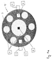
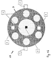
- Figures 1 and 2 show schematically in a bottom view and in cross section a system according to a first embodiment of the present invention.
- the system includes the Light source 15 and four cameras 1 to 4, the referencing of three-dimensional Space coordinates according to the optical navigation method described in DE 196 39 615 C2 serve.
- the signals captured by cameras 1 to 4 forwarded to a subordinate computer unit (not shown).
- the light source 15 has a circular cross section and comprises a central illuminant 5 and six illuminants 5 arranged in a point-symmetrical manner, each held in the housing 9 are.
- the illuminants 5 illuminate an area A essentially without shadows.
- the illuminants 5 can emit the light essentially perpendicularly from that Radiate floor of the housing 9 spanned plane or can be inclined at an angle be what is known to those skilled in the art.
- the light source 15 held above the illuminated area A for which purpose a not shown Ceiling bracket or the like is provided, as this example in the figure 3 is shown.
- Light source 15 can be positioned and / or oriented as desired relative to an object. The pretense counteract sufficient forces so that the position once taken does not change on its own.
- the light source 15 usually has a comparatively large one Diameter on, for example in the range of 60 to 80 cm.
- Luminosity and orientation the illuminants are preferably selected so that with optimal illumination of an area a usual working distance is guaranteed, for example at a distance of about 107 cm or in a range between about 91 and about 123 cm distance between Light source and work area to be illuminated.
- the infrared portion of the light emitted by the illuminants 15 can be at least partially be filtered out for what purpose in the breakthroughs in the bottom shown in FIG. 1 of the lamp housing 9 suitable optical elements are provided, for example dichroic reflectors which, depending on the wavelength, contain the infrared spectral component reflect a heat absorber, not shown, while the visible spectral component is left through the openings in the lamp housing 9.
- suitable optical elements for example dichroic reflectors which, depending on the wavelength, contain the infrared spectral component reflect a heat absorber, not shown, while the visible spectral component is left through the openings in the lamp housing 9.
- the openings can be covered with cover windows.
- additional convection openings not shown, can also be provided, so that an air flow passing through the lamp overheats the components prevented inside the lamp.
- Two cameras 1, 2 are arranged in the immediate vicinity of the peripheral edge of the light source 15, the relative to the optical axis of the light source 15 running through the handle 6 are inclined inward, as shown in FIG.
- the cameras 1, 2 can be directly on the outer peripheral edge of the lamp housing 9 or be mounted on a common Arm, either on the lamp housing 9 itself or in the immediate vicinity of the lamp housing 9 is attached.
- the holding arm not shown, can also be from the Be suspended from the ceiling.
- the field of view of the cameras is 1, 2 not covered by sections of the lamp housing 9.
- the fields of view of cameras 1, 2 overlap in area A, which is a stereoscopic spatial detection and thus a detection of three-dimensional spatial coordinates at least in area A.
- the Longitudinal axes of the cameras 1, 2 are essentially aligned with the optical axis of the light source 15. This means that the plane spanned by the longitudinal axes of the cameras 1, 2 includes the optical axis of the light source 15 which extends essentially through the handle 6 or is located close to it.
- Two further cameras 3, 4 are integrated into the interior of the lamp, which area A through recesses monitor in the bottom of the lamp housing 9. In the recesses viewing window and / or infrared filter can be attached. As can be seen in FIG. 2, the cameras 3, 4 are also inclined and overlap relative to the optical axis of the light source 15 at least in area A in order to have a stereoscopic acquisition and thus to enable referencing of three-dimensional spatial coordinates.
- the Cameras are automatically oriented so that the area A. Illuminated by the light source 15 can also be referenced.
- the cameras arranged on the outer peripheral edge of the lamp housing 9 can 1, 2 can also be arranged above the light source. So the visual fields of these cameras are not covered by the lamp housing 9, the cameras 1, 2 are radially outward staggered, namely outside a truncated cone, the boundary surfaces in the Essentially predetermined by the longitudinal axes of the cameras 1, 2 shown in FIG. 2 is.
- At least the cameras 1, 2 can also be independent of the light source 15 positioned and / or oriented.
- the one in FIG. 2 is schematic Additional handle 8 shown is provided, which in principle also in the handle 6 can be integrated.
- the angle of inclination of the cameras relative to the optical one Axis of the light source 15 can be changed, the angle of inclination of the cameras can be perpendicular can be changed to the drawing plane of Figure 2 and the radial position of the cameras can be varied.
- the adjustment can be done manually using the handle 8.
- one or more motorized adjustment elements can also be provided be, for example, individually or in groups operated by the handle 8 electrical Adjusting motors.
- the actuators can be wireless or wired with control commands be supplied.
- Suitable brackets for the cameras are available to those skilled in the field during their studies this patent description can be seen easily.
- the adjustability is directed according to the requirements and can be an axial displacement and / or a rotation around the Longitudinal axis of the cameras and / or a pivoting about the camera longitudinal axis in one or include two spatial directions and so on.
- the two groups of cameras 1, 2 and 3, 4 on a common 1b are the two groups of cameras arranged on mutually orthogonal axes that intersect in the center of the light source.
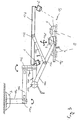
- FIG. 3 schematically shows a second embodiment of the invention in a side view System.
- This includes the light source 15 and the cameras 1, 2, which together are suspended from the ceiling by a support arm construction.
- the support arm construction includes a plurality of arms 10a-f, which are on the joints 11a, 11b axially rotatable and perpendicular to the second one in the joint regions 11c and 11b 3 are pivotable, so that a within the reach of the arms 10a-f almost any positioning and orientation of the light source 15 in relation to one to be illuminated Object can be achieved.
- the light source 15 itself comprises three lamps 5, which illuminate area A in a star-shaped, point-symmetrical arrangement.
- the cameras 1, 2 are from the common arm 12a, 12b of the camera suspension 12a, 12b held.
- the arms 12a, 12b are perpendicular to the joints 13a, 13b in the manner shown pivotable to the drawing plane of Figure 3.
- pivotable bracket instead of pivotable bracket also a relative to the light source 15 camera suspension be provided.
- the distance of the arm 12b relative to the light source 15 is preferably small, for example in the range from about 5 to about 50 cm, preferably in the range from about 5 to about 30 cm, and more preferably in the range of about 5 to about 15 cm.
- the cameras 1, 2 are inclined radially inward, so that their field of view at least in the illuminated area A overlaps to 3D referencing enable.
- a detection means can be provided in the light source 15 which is based on the orientation of the Light source 15 closes the position of the illuminated area A.
- a detection means can be provided that determines the positional relationship of cameras 1, 2 in relation to the light source 15 and thus in relation to the illuminated one Area A automatically detected.
- a computer unit calculates whether the area captured by cameras 1, 2 in which a referencing is possible (the above-mentioned overlap area), the currently illuminated area A with includes. If this is not the case, a control signal is calculated which is used for the motor Tracking cameras 1, 2 can be used.
- the cameras 1, 2 are oriented so that their fields of view are not or only insignificantly covered by the light source 15. Basically, they can Cameras 1, 2 can also be automatically adjusted by motor in the manner described above, the field of view of the cameras should be covered by the light source 15. To do this, the Computer means mentioned above Information regarding the external dimensions of the light source be available.
- the cameras are usually CCD video cameras, so the captured optical signals are available in digital form for evaluation. Based on characteristic Signal changes, for example sudden changes in intensity, can thus be determined whether the field of view of a camera is suddenly covered.
- an evaluation circuit not shown, is provided the respective electrical signals of cameras 1-4 examined. Becomes a characteristic Signal change, which suggests a concealment of the field of view of the camera, is detected, the evaluation circuit automatically changes to another of cameras 1-4 and forwards their signal to the computer unit of the referencing system.
- the electronic Signals from cameras 1-4 can also be sent periodically by the computer unit in a predetermined manner Check whether the respective field of vision is currently covered is.
- the computer unit can then determine which according to a predetermined algorithm cameras 1-4 are to be used for referencing. Because of the common Camera system and light source can be used to hold the light source 15 and video cameras 1-4 required connections as a common connection cable from the Ceiling mount 7 are led out.
- the individual components for the claimed system can also be used individually to be expelled.
- the invention is distinguished System particularly characterized by the fact that light source and video cameras are so common are held that a referencing of three-dimensional spatial coordinates in the of the Light source 15 just illuminated area is possible.
- the cameras are arranged in particular in the immediate vicinity of the light source 15.
Landscapes
- Health & Medical Sciences (AREA)
- Surgery (AREA)
- Life Sciences & Earth Sciences (AREA)
- Heart & Thoracic Surgery (AREA)
- Molecular Biology (AREA)
- Oral & Maxillofacial Surgery (AREA)
- Engineering & Computer Science (AREA)
- Biomedical Technology (AREA)
- Nuclear Medicine, Radiotherapy & Molecular Imaging (AREA)
- Medical Informatics (AREA)
- Pathology (AREA)
- Animal Behavior & Ethology (AREA)
- General Health & Medical Sciences (AREA)
- Public Health (AREA)
- Veterinary Medicine (AREA)
- Length Measuring Devices By Optical Means (AREA)
- Endoscopes (AREA)
Claims (9)
- Système combiné d'éclairage d'une zone (A) prédéterminable et de référencement de coordonnées dans l'espace à trois dimensions, en particulier d'instruments chirurgicaux ou médicaux, qui comprend:une lampe d'opération (15) qui éclaire la zone,une source de rayonnement qui émet un rayonnement infrarouge etau moins deux caméras (1-4) qui détectent des signaux optiques infrarouge,la lampe d'opération (15) et les caméras (1 à 4) étant maintenues ensemble de telle sorte que les signaux optiques infrarouges puissent être évalués pour référencer des coordonnées dans l'espace à trois dimensions dans la zone éclairée (A).
- Système selon la revendication 1, dans lequel au moins deux caméras (1, 2) sont disposées à l'extérieur d'un boítier (9) de la lampe d'opération à proximité d'un bord périphérique du boítier de telle sorte que la vue des caméras sur la zone éclairée (A) ne soit pas recouverte par les parties du boítier.
- Système selon les revendications 1 ou 2, dans lequel au moins deux caméras (3, 4) sont intégrées dans un boítier (9) de la lampe d'opération, des hublots étant prévus pour chacune des caméras dans des parties du boítier dans lesquelles aucun moyen d'éclairage (5) de la lampe d'opération (15) n'est disposé.
- Système selon l'une des revendications précédentes, dans lequel la lampe d'opération (15) et au moins deux caméras sont reliées rigidement l'une à l'autre de telle sorte que la lampe d'opération et les caméras puissent être déplacées ensemble.
- Système selon l'une des revendications 1 à 3, dans lequel l'orientation et/ou la position d'au moins deux caméras par rapport à la lampe d'opération (15) sont ajustables.
- Système selon la revendication 5, dans lequel au moins deux caméras (1, 2; 3, 4) disposées sur des côtés opposés de la lampe d'opération (15) peuvent être déplacées ensemble, un angle d'inclinaison des caméras pouvant être ajusté dans les deux sens par rapport au centre de la lampe d'opération.
- Système selon l'une des revendications précédentes, dans lequel au moins deux caméras sont disposées essentiellement à symétrie centrale par rapport au milieu de la lampe d'opération (15).
- Système selon l'une des revendications précédentes, dans lequel les caméras sont dotées de filtres de transmission infrarouges qui détectent le rayonnement infrarouge réfléchi par des réflecteurs ou émis par des sources de lumière, la portion infrarouge de la lumière émise par la lampe d'opération (15) étant filtrée au moins en partie.
- Système selon l'une des revendications précédentes, qui comprend au moins trois caméras, un système d'évaluation étant prévu pour évaluer les signaux détectés par les caméras pour détecter quand le champ de vision d'au moins une caméra est recouvert et pour, en vue du référencement, passer de la caméra dont le champ de vision est recouvert à une autre caméra de la pluralité de caméras dont le champ de vision n'est pas recouvert.
Priority Applications (5)
| Application Number | Priority Date | Filing Date | Title |
|---|---|---|---|
| ES02004345T ES2225668T3 (es) | 2002-03-01 | 2002-03-01 | Lampara para sala de operadciones, que incluye un sistema de camaras para referenciacion tridimensional. |
| EP02004345A EP1340470B1 (fr) | 2002-03-01 | 2002-03-01 | Lampe pour salle d'opération comportant un système de caméras pour référencement tri-dimensionnel |
| DE50201004T DE50201004D1 (de) | 2002-03-01 | 2002-03-01 | Operationslampe mit Kamerasystem zur 3D-Referenzierung |
| AT02004345T ATE275881T1 (de) | 2002-03-01 | 2002-03-01 | Operationslampe mit kamerasystem zur 3d- referenzierung |
| US10/134,976 US7224472B2 (en) | 2002-03-01 | 2002-04-29 | Operation lamp with camera system for 3D referencing |
Applications Claiming Priority (1)
| Application Number | Priority Date | Filing Date | Title |
|---|---|---|---|
| EP02004345A EP1340470B1 (fr) | 2002-03-01 | 2002-03-01 | Lampe pour salle d'opération comportant un système de caméras pour référencement tri-dimensionnel |
Publications (2)
| Publication Number | Publication Date |
|---|---|
| EP1340470A1 EP1340470A1 (fr) | 2003-09-03 |
| EP1340470B1 true EP1340470B1 (fr) | 2004-09-15 |
Family
ID=27675641
Family Applications (1)
| Application Number | Title | Priority Date | Filing Date |
|---|---|---|---|
| EP02004345A Expired - Lifetime EP1340470B1 (fr) | 2002-03-01 | 2002-03-01 | Lampe pour salle d'opération comportant un système de caméras pour référencement tri-dimensionnel |
Country Status (5)
| Country | Link |
|---|---|
| US (1) | US7224472B2 (fr) |
| EP (1) | EP1340470B1 (fr) |
| AT (1) | ATE275881T1 (fr) |
| DE (1) | DE50201004D1 (fr) |
| ES (1) | ES2225668T3 (fr) |
Cited By (2)
| Publication number | Priority date | Publication date | Assignee | Title |
|---|---|---|---|---|
| CN101868191B (zh) * | 2007-11-19 | 2012-01-25 | 库卡实验仪器有限公司 | 确定导航系统检测装置的位置及定位该检测装置的方法 |
| DE102013202575B4 (de) * | 2013-02-18 | 2014-09-11 | Leica Microsystems (Schweiz) Ag | Operationsbeleuchtungseinrichtung |
Families Citing this family (42)
| Publication number | Priority date | Publication date | Assignee | Title |
|---|---|---|---|---|
| DE10225077B4 (de) * | 2002-06-05 | 2007-11-15 | Vr Magic Gmbh | Objektverfolgeanordnung für medizinische Operationen |
| US7619784B1 (en) | 2003-06-30 | 2009-11-17 | Google Inc. | Pacing and error monitoring of manual page turning operator |
| US7639406B1 (en) | 2003-06-30 | 2009-12-29 | Google Inc. | Movable document cradle for facilitating imaging of bound documents |
| US7586655B1 (en) * | 2003-06-30 | 2009-09-08 | Google Inc. | Acquiring and using three-dimensional information in a document scanning system |
| US7605844B1 (en) | 2003-11-13 | 2009-10-20 | Google Inc. | Imaging opposing bound pages at high speed using multiple cameras |
| WO2005067807A1 (fr) * | 2004-01-09 | 2005-07-28 | Ecole Polytechnique Federale De Lausanne (Epfl) | Systeme de navigation chirurgicale |
| US7567833B2 (en) * | 2004-03-08 | 2009-07-28 | Stryker Leibinger Gmbh & Co. Kg | Enhanced illumination device and method |
| DE102004046430A1 (de) * | 2004-09-24 | 2006-04-06 | Siemens Ag | System zur visuellen Situations-bedingten Echtzeit-basierten Unterstützung eines Chirurgen und Echtzeit-basierter Dokumentation und Archivierung der vom Chirurgen während der Operation visuell wahrgenommenen Unterstützungs-basierten Eindrücke |
| US7623250B2 (en) * | 2005-02-04 | 2009-11-24 | Stryker Leibinger Gmbh & Co. Kg. | Enhanced shape characterization device and method |
| DE502005010754D1 (de) * | 2005-05-31 | 2011-02-10 | Brainlab Ag | Selbsteinstellendes Operationslampensystem |
| US7706683B2 (en) | 2005-05-31 | 2010-04-27 | Brainlab Ag | Self adjusting operation lamp system |
| US8253736B2 (en) * | 2007-01-29 | 2012-08-28 | Microsoft Corporation | Reducing occlusions in oblique views |
| EP2026577A1 (fr) * | 2007-08-08 | 2009-02-18 | TRUMPF Medizin Systeme GmbH + Co. KG | Procédé destiné à la transmission d'un signal vidéo d'une caméra installée sur un système d'éclairage OP et système d'éclairage OP |
| DE102008019191B4 (de) * | 2008-04-17 | 2017-10-05 | Drägerwerk AG & Co. KGaA | Vorrichtung und Verfahren zur gleichmäßigen Ausleuchtung eines Operationsfeldes |
| DE102009007986A1 (de) * | 2009-02-07 | 2010-08-12 | Radl, Bernd, Dr. | Vorrichtung zur Beleuchtung eines Operationsfeldes eines sterilen Operationsraumes |
| US10371411B2 (en) | 2009-10-22 | 2019-08-06 | Nortek Air Solutions, Llc | Ceiling system with integrated equipment support structure |
| ES2377893B1 (es) * | 2010-02-08 | 2012-10-26 | Carlos Jesús Vega Vera | Sistema de detección óptica de posición 3d con cámara única. |
| FR2963093B1 (fr) * | 2010-07-26 | 2012-08-03 | Vit | Installation d'inspection optique 3d de circuits electroniques |
| US9687305B2 (en) * | 2011-01-14 | 2017-06-27 | Ondal Holding Gmbh | Lighting device |
| FR2974473B1 (fr) | 2011-04-19 | 2013-11-08 | Maquet S A | Dispositif de surveillance, utilisation d'un tel dispositif de surveillance et installation d'operation comprenant un tel dispositif de surveillance |
| US8976236B2 (en) | 2011-11-08 | 2015-03-10 | Mary Maitland DeLAND | Surgical light and video control system and method of use |
| US9186053B2 (en) | 2012-05-03 | 2015-11-17 | Covidien Lp | Methods of using light to repair hernia defects |
| WO2013173258A1 (fr) * | 2012-05-15 | 2013-11-21 | The Cleveland Clinic Foundation | Éclairage de bloc opératoire intégré |
| CA2925620C (fr) | 2012-10-29 | 2020-07-21 | 7D Surgical Inc. | Systeme integre d'eclairage et de detection de topologie de surface optique et procedes d'utilisation de ce dernier |
| JP6153128B2 (ja) * | 2013-04-19 | 2017-06-28 | 清水建設株式会社 | 手術室用照明装置及びこれを備えた手術室 |
| DE102013012231B4 (de) * | 2013-07-23 | 2022-07-14 | Drägerwerk AG & Co. KGaA | Verfahren für die Verbesserung der Ausleuchtung eines Ausleuchtbereichs einer Ausleuchtvorrichtung |
| DE202013007639U1 (de) | 2013-08-27 | 2013-11-13 | Benno Raddatz | Modulare Multifunktions-Behandlungs- und Operationsleuchte für die Medizin und Zahnmedizin |
| FR3018592A1 (fr) * | 2014-03-12 | 2015-09-18 | Maquet Sas | Dispositif d'eclairage scialytique incluant une fonction de mesure de distance entre deux marqueurs |
| US9794453B2 (en) * | 2014-09-11 | 2017-10-17 | James A Weingard | Illumination apparatus interposable during examination procedure |
| DE102015113339A1 (de) * | 2015-08-13 | 2017-02-16 | Karl Leibinger Medizintechnik Gmbh & Co. Kg | Operationsleuchte mit Helligkeitsregulierung |
| WO2017042171A1 (fr) | 2015-09-10 | 2017-03-16 | Koninklijke Philips N.V. | Appareil d'imagerie dans un traitement médical |
| FI20175247A (fi) * | 2017-03-17 | 2018-09-18 | Planmeca Oy | Hammashoitokoneen operaatiovalaisin |
| US10999493B2 (en) * | 2017-12-22 | 2021-05-04 | Medtech S.A. | Scialytic light navigation |
| CN111886933A (zh) | 2018-02-09 | 2020-11-03 | 金泰克斯公司 | 用于检测和照射感兴趣区的系统和方法 |
| WO2019155426A1 (fr) * | 2018-02-09 | 2019-08-15 | Gentex Corporation | Réseau d'éclairage adaptatif à commande basée sur l'image |
| US11291507B2 (en) | 2018-07-16 | 2022-04-05 | Mako Surgical Corp. | System and method for image based registration and calibration |
| US11484382B2 (en) | 2019-04-24 | 2022-11-01 | American Sterilizer Company | System and method for identification of illumination abnormalities and automatic compensation therefor |
| JP7286815B2 (ja) | 2019-06-20 | 2023-06-05 | ジェンテックス コーポレイション | 物体追跡のための照明システム及び方法 |
| EP3969882A4 (fr) * | 2019-06-20 | 2022-06-29 | Gentex Corporation | Système et procédé de déploiement et d'éclairage modulaires automatisés |
| WO2021074824A1 (fr) | 2019-10-15 | 2021-04-22 | Gentex Corporation | Module lumineux à panneau plat avec faisceau dynamique |
| US11317973B2 (en) * | 2020-06-09 | 2022-05-03 | Globus Medical, Inc. | Camera tracking bar for computer assisted navigation during surgery |
| WO2023021481A1 (fr) | 2021-08-20 | 2023-02-23 | Gentex Corporation | Ensemble d'éclairage et système d'éclairage présentant un ensemble d'éclairage |
Family Cites Families (25)
| Publication number | Priority date | Publication date | Assignee | Title |
|---|---|---|---|---|
| GB834840A (en) * | 1957-05-29 | 1960-05-11 | Associated Television Ltd | Improvements in lighting arrangements |
| DE3929628A1 (de) * | 1989-09-06 | 1991-03-07 | Heraeus Gmbh W C | Bilduebertragungssystem in operationsleuchten |
| US6405072B1 (en) * | 1991-01-28 | 2002-06-11 | Sherwood Services Ag | Apparatus and method for determining a location of an anatomical target with reference to a medical apparatus |
| JP3485583B2 (ja) * | 1992-07-08 | 2004-01-13 | 株式会社トプコン | 医用顕微鏡システム |
| IL104423A (en) * | 1993-01-18 | 1998-09-24 | Opgal Optronic Ind Ltd | Infra-red vascular angiography system |
| GB9405299D0 (en) * | 1994-03-17 | 1994-04-27 | Roke Manor Research | Improvements in or relating to video-based systems for computer assisted surgery and localisation |
| EP0736725B1 (fr) * | 1995-04-07 | 1999-09-01 | Heraeus Med GmbH | Procédé de transmission de signals vidéo et système de transmission des images pour appareil d'éclairage chirurgical |
| US6122541A (en) * | 1995-05-04 | 2000-09-19 | Radionics, Inc. | Head band for frameless stereotactic registration |
| US5852672A (en) * | 1995-07-10 | 1998-12-22 | The Regents Of The University Of California | Image system for three dimensional, 360 DEGREE, time sequence surface mapping of moving objects |
| DE19639615C5 (de) | 1996-09-26 | 2008-11-06 | Brainlab Ag | Reflektorenreferenzierungssystem für chirurgische und medizinische Instrumente |
| GB9604992D0 (en) * | 1996-03-08 | 1996-05-08 | Univ Hull | Surgical positioning apparatus and methods |
| US5803905A (en) * | 1996-03-28 | 1998-09-08 | Ajor Medical Technologies, L.L.C. | Surgical camera and light assembly allowing adjustable focus and zoom capability and method of use |
| US6167296A (en) * | 1996-06-28 | 2000-12-26 | The Board Of Trustees Of The Leland Stanford Junior University | Method for volumetric image navigation |
| US5745545A (en) * | 1996-08-16 | 1998-04-28 | Siemens Medical Systems, Inc. | Alignment system and method for intra-operative radiation therapy |
| US5864640A (en) * | 1996-10-25 | 1999-01-26 | Wavework, Inc. | Method and apparatus for optically scanning three dimensional objects using color information in trackable patches |
| WO1999001078A2 (fr) * | 1997-07-03 | 1999-01-14 | Koninklijke Philips Electronics N.V. | Systeme de chirurgie guide par l'image |
| US5924976A (en) * | 1997-08-21 | 1999-07-20 | Stelzer; Paul | Minimally invasive surgery device |
| JPH11155142A (ja) * | 1997-11-19 | 1999-06-08 | Mitsubishi Electric Corp | 医療支援システム |
| US6328458B1 (en) * | 1998-03-30 | 2001-12-11 | Hill-Rom Services, Inc. | Support arm for surgical light apparatus |
| US6359647B1 (en) * | 1998-08-07 | 2002-03-19 | Philips Electronics North America Corporation | Automated camera handoff system for figure tracking in a multiple camera system |
| US6633328B1 (en) * | 1999-01-05 | 2003-10-14 | Steris Corporation | Surgical lighting system with integrated digital video camera |
| CA2272040A1 (fr) * | 1999-05-13 | 2000-11-13 | Ecole Polytechnique | Systeme de camera d'observation robotisee pour utilisation en salle d'operation |
| IL147530A0 (en) * | 1999-07-13 | 2002-08-14 | Surgivision Ltd | Stereoscopic video observation and image magnification system |
| ES2180481T3 (es) * | 2000-04-05 | 2003-02-16 | Brainlab Ag | Referenciacion de un paciente en un sistema de navegacion medica, utilizando puntos luminosos proyectados. |
| US20020082498A1 (en) * | 2000-10-05 | 2002-06-27 | Siemens Corporate Research, Inc. | Intra-operative image-guided neurosurgery with augmented reality visualization |
-
2002
- 2002-03-01 ES ES02004345T patent/ES2225668T3/es not_active Expired - Lifetime
- 2002-03-01 EP EP02004345A patent/EP1340470B1/fr not_active Expired - Lifetime
- 2002-03-01 AT AT02004345T patent/ATE275881T1/de not_active IP Right Cessation
- 2002-03-01 DE DE50201004T patent/DE50201004D1/de not_active Expired - Lifetime
- 2002-04-29 US US10/134,976 patent/US7224472B2/en not_active Expired - Lifetime
Cited By (2)
| Publication number | Priority date | Publication date | Assignee | Title |
|---|---|---|---|---|
| CN101868191B (zh) * | 2007-11-19 | 2012-01-25 | 库卡实验仪器有限公司 | 确定导航系统检测装置的位置及定位该检测装置的方法 |
| DE102013202575B4 (de) * | 2013-02-18 | 2014-09-11 | Leica Microsystems (Schweiz) Ag | Operationsbeleuchtungseinrichtung |
Also Published As
| Publication number | Publication date |
|---|---|
| EP1340470A1 (fr) | 2003-09-03 |
| US7224472B2 (en) | 2007-05-29 |
| ATE275881T1 (de) | 2004-10-15 |
| DE50201004D1 (de) | 2004-10-21 |
| ES2225668T3 (es) | 2005-03-16 |
| US20030164953A1 (en) | 2003-09-04 |
Similar Documents
| Publication | Publication Date | Title |
|---|---|---|
| EP1340470B1 (fr) | Lampe pour salle d'opération comportant un système de caméras pour référencement tri-dimensionnel | |
| EP2434202B2 (fr) | Lampe d'opération dotée d'un dispositif de commande stérile | |
| EP1728482B1 (fr) | Système de lampe chirurgicale autoajustable | |
| EP1750053B2 (fr) | Système de lampes scialytiques | |
| EP2283790B1 (fr) | Commande et procédé de fonctionnement d'une lampe d'opération | |
| DE102005008153A1 (de) | Endoskopische Beobachtungseinrichtung | |
| EP2039296A2 (fr) | Dispositif d'éclairage pour un dispositif d'examen médical | |
| DE102005010009A1 (de) | Verbesserter Beleuchtungsapparat und Verfahren hierzu | |
| EP2136129A1 (fr) | Eclairage d'opération doté d'un réglage de la luminosité dépendant de l'intervalle | |
| DE102008018922A1 (de) | Bildgebende Systeme und Verfahren, insbesondere zur Verwendung mit einem bei offener Chirurgie verwendeten Instrument | |
| EP1333306A2 (fr) | Procédé et dispositif de microscopie stéréoscopique | |
| DE102014103044A1 (de) | Chirurgisches Assistenzsystem | |
| DE102004055839B4 (de) | Operationsleuchte | |
| DE102005013042A1 (de) | Einrichtung zur Erzeugung von 3D-Fluoreszenz-oder Lumineszenz-Scans | |
| DE102011007201A1 (de) | Verfahren und Anordnung zur Regelung einer medizinischen Operationsleuchte | |
| EP1291696B1 (fr) | Configuration de prismes pour une illumination normale et oblique dans un stéréomicroscope chirurgical | |
| DE10323091A1 (de) | OP-Feldbeleuchtungsvorrichtung | |
| DE102010013499A1 (de) | Verfahren zur Ausrichtung einer stereoskopischen Bildgebungseinrichtung eines optischen Trackingssystems, Trackingsystem und medizinisches Behandlungssystem | |
| EP3632294B1 (fr) | Système et procédé de retenue d'un dispositif de reproduction d'images | |
| EP4157134A1 (fr) | Système de surveillance d'un système d'éclairage chirurgical | |
| DE102008010990A1 (de) | Einrichtung umfassend ein im Raum bewegbares, zu betrachtendes Objekt, insbesondere medizinische Untersuchungs- oder Behandlungseinrichtung mit einer im Raum bewegbaren Anzeigevorrichtung | |
| WO2021239873A1 (fr) | Système de surveillance d'un ensemble lampe chirurgicale | |
| DE102018206405B3 (de) | Mikroskopiesystem sowie Verfahren zum Betrieb eines Mikroskopiesystems | |
| EP1733693B1 (fr) | Système de localisation et de suivi pour équipement médical avec transmission infrarouge | |
| DE102017216852A1 (de) | Visualisierungssystem mit einer Beleuchtungsvorrichtung |
Legal Events
| Date | Code | Title | Description |
|---|---|---|---|
| PUAI | Public reference made under article 153(3) epc to a published international application that has entered the european phase |
Free format text: ORIGINAL CODE: 0009012 |
|
| 17P | Request for examination filed |
Effective date: 20020301 |
|
| AK | Designated contracting states |
Kind code of ref document: A1 Designated state(s): AT BE CH CY DE DK ES FI FR GB GR IE IT LI LU MC NL PT SE TR |
|
| AX | Request for extension of the european patent |
Extension state: AL LT LV MK RO SI |
|
| GRAP | Despatch of communication of intention to grant a patent |
Free format text: ORIGINAL CODE: EPIDOSNIGR1 |
|
| AKX | Designation fees paid |
Designated state(s): AT BE CH CY DE DK ES FI FR GB GR IE IT LI LU MC NL PT SE TR |
|
| GRAS | Grant fee paid |
Free format text: ORIGINAL CODE: EPIDOSNIGR3 |
|
| GRAA | (expected) grant |
Free format text: ORIGINAL CODE: 0009210 |
|
| AK | Designated contracting states |
Kind code of ref document: B1 Designated state(s): AT BE CH CY DE DK ES FI FR GB GR IE IT LI LU MC NL PT SE TR |
|
| PG25 | Lapsed in a contracting state [announced via postgrant information from national office to epo] |
Ref country code: FI Free format text: LAPSE BECAUSE OF FAILURE TO SUBMIT A TRANSLATION OF THE DESCRIPTION OR TO PAY THE FEE WITHIN THE PRESCRIBED TIME-LIMIT Effective date: 20040915 Ref country code: IE Free format text: LAPSE BECAUSE OF FAILURE TO SUBMIT A TRANSLATION OF THE DESCRIPTION OR TO PAY THE FEE WITHIN THE PRESCRIBED TIME-LIMIT Effective date: 20040915 Ref country code: NL Free format text: LAPSE BECAUSE OF FAILURE TO SUBMIT A TRANSLATION OF THE DESCRIPTION OR TO PAY THE FEE WITHIN THE PRESCRIBED TIME-LIMIT Effective date: 20040915 Ref country code: TR Free format text: LAPSE BECAUSE OF FAILURE TO SUBMIT A TRANSLATION OF THE DESCRIPTION OR TO PAY THE FEE WITHIN THE PRESCRIBED TIME-LIMIT Effective date: 20040915 |
|
| REG | Reference to a national code |
Ref country code: CH Ref legal event code: EP Ref country code: CH Ref legal event code: NV Representative=s name: RIEDERER HASLER & PARTNER PATENTANWAELTE AG Ref country code: GB Ref legal event code: FG4D Free format text: NOT ENGLISH |
|
| GBT | Gb: translation of ep patent filed (gb section 77(6)(a)/1977) |
Effective date: 20040917 |
|
| REG | Reference to a national code |
Ref country code: IE Ref legal event code: FG4D Free format text: GERMAN |
|
| REF | Corresponds to: |
Ref document number: 50201004 Country of ref document: DE Date of ref document: 20041021 Kind code of ref document: P |
|
| PG25 | Lapsed in a contracting state [announced via postgrant information from national office to epo] |
Ref country code: DK Free format text: LAPSE BECAUSE OF FAILURE TO SUBMIT A TRANSLATION OF THE DESCRIPTION OR TO PAY THE FEE WITHIN THE PRESCRIBED TIME-LIMIT Effective date: 20041215 Ref country code: SE Free format text: LAPSE BECAUSE OF FAILURE TO SUBMIT A TRANSLATION OF THE DESCRIPTION OR TO PAY THE FEE WITHIN THE PRESCRIBED TIME-LIMIT Effective date: 20041215 Ref country code: GR Free format text: LAPSE BECAUSE OF FAILURE TO SUBMIT A TRANSLATION OF THE DESCRIPTION OR TO PAY THE FEE WITHIN THE PRESCRIBED TIME-LIMIT Effective date: 20041215 |
|
| PG25 | Lapsed in a contracting state [announced via postgrant information from national office to epo] |
Ref country code: CY Free format text: LAPSE BECAUSE OF FAILURE TO SUBMIT A TRANSLATION OF THE DESCRIPTION OR TO PAY THE FEE WITHIN THE PRESCRIBED TIME-LIMIT Effective date: 20050301 Ref country code: LU Free format text: LAPSE BECAUSE OF NON-PAYMENT OF DUE FEES Effective date: 20050301 |
|
| REG | Reference to a national code |
Ref country code: ES Ref legal event code: FG2A Ref document number: 2225668 Country of ref document: ES Kind code of ref document: T3 |
|
| PG25 | Lapsed in a contracting state [announced via postgrant information from national office to epo] |
Ref country code: MC Free format text: LAPSE BECAUSE OF NON-PAYMENT OF DUE FEES Effective date: 20050331 |
|
| NLV1 | Nl: lapsed or annulled due to failure to fulfill the requirements of art. 29p and 29m of the patents act | ||
| REG | Reference to a national code |
Ref country code: IE Ref legal event code: FD4D |
|
| PLBE | No opposition filed within time limit |
Free format text: ORIGINAL CODE: 0009261 |
|
| STAA | Information on the status of an ep patent application or granted ep patent |
Free format text: STATUS: NO OPPOSITION FILED WITHIN TIME LIMIT |
|
| ET | Fr: translation filed | ||
| 26N | No opposition filed |
Effective date: 20050616 |
|
| PGFP | Annual fee paid to national office [announced via postgrant information from national office to epo] |
Ref country code: AT Payment date: 20070313 Year of fee payment: 6 |
|
| PGFP | Annual fee paid to national office [announced via postgrant information from national office to epo] |
Ref country code: CH Payment date: 20070314 Year of fee payment: 6 |
|
| PG25 | Lapsed in a contracting state [announced via postgrant information from national office to epo] |
Ref country code: PT Free format text: LAPSE BECAUSE OF NON-PAYMENT OF DUE FEES Effective date: 20050215 |
|
| PGFP | Annual fee paid to national office [announced via postgrant information from national office to epo] |
Ref country code: BE Payment date: 20070419 Year of fee payment: 6 |
|
| PGFP | Annual fee paid to national office [announced via postgrant information from national office to epo] |
Ref country code: ES Payment date: 20080328 Year of fee payment: 7 |
|
| PGFP | Annual fee paid to national office [announced via postgrant information from national office to epo] |
Ref country code: IT Payment date: 20080326 Year of fee payment: 7 |
|
| BERE | Be: lapsed |
Owner name: *BRAINLAB A.G. Effective date: 20080331 |
|
| REG | Reference to a national code |
Ref country code: CH Ref legal event code: PL |
|
| PG25 | Lapsed in a contracting state [announced via postgrant information from national office to epo] |
Ref country code: AT Free format text: LAPSE BECAUSE OF NON-PAYMENT OF DUE FEES Effective date: 20080301 |
|
| PG25 | Lapsed in a contracting state [announced via postgrant information from national office to epo] |
Ref country code: CH Free format text: LAPSE BECAUSE OF NON-PAYMENT OF DUE FEES Effective date: 20080331 Ref country code: LI Free format text: LAPSE BECAUSE OF NON-PAYMENT OF DUE FEES Effective date: 20080331 |
|
| PG25 | Lapsed in a contracting state [announced via postgrant information from national office to epo] |
Ref country code: BE Free format text: LAPSE BECAUSE OF NON-PAYMENT OF DUE FEES Effective date: 20080331 |
|
| REG | Reference to a national code |
Ref country code: ES Ref legal event code: FD2A Effective date: 20090302 |
|
| PGFP | Annual fee paid to national office [announced via postgrant information from national office to epo] |
Ref country code: FR Payment date: 20100402 Year of fee payment: 9 |
|
| PGFP | Annual fee paid to national office [announced via postgrant information from national office to epo] |
Ref country code: GB Payment date: 20100322 Year of fee payment: 9 |
|
| PG25 | Lapsed in a contracting state [announced via postgrant information from national office to epo] |
Ref country code: ES Free format text: LAPSE BECAUSE OF NON-PAYMENT OF DUE FEES Effective date: 20090302 |
|
| PG25 | Lapsed in a contracting state [announced via postgrant information from national office to epo] |
Ref country code: IT Free format text: LAPSE BECAUSE OF NON-PAYMENT OF DUE FEES Effective date: 20090301 |
|
| GBPC | Gb: european patent ceased through non-payment of renewal fee |
Effective date: 20110301 |
|
| REG | Reference to a national code |
Ref country code: FR Ref legal event code: ST Effective date: 20111130 |
|
| PG25 | Lapsed in a contracting state [announced via postgrant information from national office to epo] |
Ref country code: FR Free format text: LAPSE BECAUSE OF NON-PAYMENT OF DUE FEES Effective date: 20110331 |
|
| PG25 | Lapsed in a contracting state [announced via postgrant information from national office to epo] |
Ref country code: GB Free format text: LAPSE BECAUSE OF NON-PAYMENT OF DUE FEES Effective date: 20110301 |
|
| REG | Reference to a national code |
Ref country code: DE Ref legal event code: R082 Ref document number: 50201004 Country of ref document: DE Representative=s name: SCHWABE SANDMAIR MARX, DE |
|
| REG | Reference to a national code |
Ref country code: DE Ref legal event code: R081 Ref document number: 50201004 Country of ref document: DE Owner name: BRAINLAB AG, DE Free format text: FORMER OWNER: BRAINLAB AG, 85622 FELDKIRCHEN, DE Effective date: 20131104 Ref country code: DE Ref legal event code: R082 Ref document number: 50201004 Country of ref document: DE Representative=s name: SCHWABE SANDMAIR MARX, DE Effective date: 20131104 Ref country code: DE Ref legal event code: R082 Ref document number: 50201004 Country of ref document: DE Representative=s name: SCHWABE SANDMAIR MARX PATENTANWAELTE RECHTSANW, DE Effective date: 20131104 |
|
| REG | Reference to a national code |
Ref country code: DE Ref legal event code: R082 Ref document number: 50201004 Country of ref document: DE Representative=s name: SSM SANDMAIR PATENTANWAELTE RECHTSANWALT PARTN, DE Ref country code: DE Ref legal event code: R082 Ref document number: 50201004 Country of ref document: DE Representative=s name: SCHWABE SANDMAIR MARX PATENTANWAELTE RECHTSANW, DE Ref country code: DE Ref legal event code: R081 Ref document number: 50201004 Country of ref document: DE Owner name: BRAINLAB AG, DE Free format text: FORMER OWNER: BRAINLAB AG, 85622 FELDKIRCHEN, DE |
|
| PGFP | Annual fee paid to national office [announced via postgrant information from national office to epo] |
Ref country code: DE Payment date: 20210319 Year of fee payment: 20 |
|
| REG | Reference to a national code |
Ref country code: DE Ref legal event code: R071 Ref document number: 50201004 Country of ref document: DE |