EP1340449A1 - Fussabstreifer - Google Patents
Fussabstreifer Download PDFInfo
- Publication number
- EP1340449A1 EP1340449A1 EP02002512A EP02002512A EP1340449A1 EP 1340449 A1 EP1340449 A1 EP 1340449A1 EP 02002512 A EP02002512 A EP 02002512A EP 02002512 A EP02002512 A EP 02002512A EP 1340449 A1 EP1340449 A1 EP 1340449A1
- Authority
- EP
- European Patent Office
- Prior art keywords
- support element
- support
- side parts
- scraper
- chamber
- Prior art date
- Legal status (The legal status is an assumption and is not a legal conclusion. Google has not performed a legal analysis and makes no representation as to the accuracy of the status listed.)
- Granted
Links
- 238000007373 indentation Methods 0.000 claims description 12
- 239000000853 adhesive Substances 0.000 claims description 10
- 230000001070 adhesive effect Effects 0.000 claims description 10
- 239000000969 carrier Substances 0.000 claims description 6
- 239000000463 material Substances 0.000 claims description 4
- 241001295925 Gegenes Species 0.000 description 3
- 238000001035 drying Methods 0.000 description 2
- 238000004519 manufacturing process Methods 0.000 description 2
- 240000003517 Elaeocarpus dentatus Species 0.000 description 1
- XAGFODPZIPBFFR-UHFFFAOYSA-N aluminium Chemical compound [Al] XAGFODPZIPBFFR-UHFFFAOYSA-N 0.000 description 1
- 229910052782 aluminium Inorganic materials 0.000 description 1
- 238000004873 anchoring Methods 0.000 description 1
- 230000009286 beneficial effect Effects 0.000 description 1
- 230000015572 biosynthetic process Effects 0.000 description 1
- 230000006735 deficit Effects 0.000 description 1
- 238000006073 displacement reaction Methods 0.000 description 1
- 229920001971 elastomer Polymers 0.000 description 1
- 239000000806 elastomer Substances 0.000 description 1
- 238000009434 installation Methods 0.000 description 1
- 239000002245 particle Substances 0.000 description 1
- 239000007787 solid Substances 0.000 description 1
- 125000006850 spacer group Chemical group 0.000 description 1
Images


Classifications
-
- A—HUMAN NECESSITIES
- A47—FURNITURE; DOMESTIC ARTICLES OR APPLIANCES; COFFEE MILLS; SPICE MILLS; SUCTION CLEANERS IN GENERAL
- A47L—DOMESTIC WASHING OR CLEANING; SUCTION CLEANERS IN GENERAL
- A47L23/00—Cleaning footwear
- A47L23/22—Devices or implements resting on the floor for removing mud, dirt, or dust from footwear
- A47L23/26—Mats or gratings combined with brushes ; Mats
Definitions
- the invention relates to a scraper which has numerous profile carriers which run approximately parallel to one another and which are connected to one another via rigid or flexible connecting links.
- the underside of the support element is also flat, so that it lies flat on the surface of a floor. Installation of such support elements is complex and not suitable for absorbing foreign bodies that can fundamentally collect on the floor. Foreign bodies therefore easily settle in the flat part of the support surface of the support element.
- the invention has for its object to design and arrange the profile strip and the associated support elements such that they are easily assembled and also suitable for absorbing the foreign bodies lying on the floor in the support element in such a way that a non-slip support of the scraper is ensured ,
- the lower Part of the profile bar can be easily in the lower Opening and be anchored so that they are do not move in the lower chamber. This is it advantageous that the surface over the entire length lies flat against the lower side of the crossbar and over an adhesive is firmly attached to this.
- the support element in the Cross-sectional profile is approximately U-shaped.
- the U-shaped cross-sectional profile of the support element is obtained in a simple way, the chambers on the Dirt adhering to the floor, e.g. stones, can absorb without the requirement of the Scraper on the floor surface is affected.
- the individual Support elements that make contact with the surface of the floor have, are relatively narrow.
- the bead-like support parts and / or the stripping elements or the side parts or have several recesses into which the Fasteners are recessed to the bottom Support elements and / or the upper stripping elements or are arranged on the side parts. This gives you a perfect attachment between the profile strip and the support element.
- the solution according to the invention provides that the support part is truncated pyramid.
- the support part is a curved, downward-facing Surface. Due to the domed formation of the Support element will keep the ground contact to a minimum reduced without the quality of the stripping mat affect the floor surface.
- the support element an elastomeric or rubber-like material is.
- the support element and / or the lower crossbars on one surface structured or roughened or with recesses have provided surface.
- the roughened Surface of the crossbars or the surface of the Supporting element ensures that the built-in Condition of the support element in the lower chamber none Moving takes place in the longitudinal direction of the profile beam. This creates a good interlocking between the two connecting elements created.
- a suitable adhesive can reduce the liability between the crossbar and the support element significantly improved become.
- the support element on its one surface with respect to its longitudinal direction has transverse recesses for receiving serve an adhesive.
- the upper cross bar also serves as a wiping element trained so that an assembly of additional Scraper elements is eliminated.
- the support parts on the both ends of a flat web part arranged and are bead-like or also formed as a web part.
- the inventive design of the support elements with the downward, web-shaped support parts allows it to be easily designed in any shape Use profile beams and with them permanently and connect non-slip, so that a displacement of the Support elements in the profile beams is avoided.
- the support elements as already mentioned, correspondingly structured on the surface be so that a good interlocking with the corresponding Opposite side of the profile beam can be done.
- the support parts are truncated pyramid-shaped.
- the support element is a Width B has about three to four times as large is like the height H of the support element.
- the overall profile height of the profile strips are kept small, so that they can be embedded in a floor to save space can. Due to the advantageous embodiment of the Bulge with the sloping side surfaces a concentration of dirt or small stones favored within the bulge, so that this is do not deposit on the flat areas of the support elements.
- a profile carrier 1 is in FIG. 2 not shown, part of one in the drawing shown scraper or an entrance floor folder which is described in detail in patent specification DE 44 07 231 C2, Columns 5 to 8 is described.
- the one shown in Figure 1 Profile beam can also not in the drawing shown rope-like connecting elements or according 3 via rigid or flexible connecting members 41 be connected to each other. Several in parallel extending profile beams then form a wiper or a floor mat.
- Hollow-shaped can be between the individual profile beams 1 or sleeve-like, on the rope-like connecting elements Arranged spacers ensure that the individual Profile carrier 1 an even distance apart exhibit.
- the extreme end of each Connecting element which can be designed as a rope, is fixed or detachable with the outside Profile carrier 1 connected.
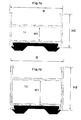
- FIG. 2 is a first embodiment of a Profile carrier 1 illustrated in more detail.
- the profile beam 1 consists of two parallel side parts 4.1 and 4.2, also arranged at right angles to it parallel crossbars 5.1 and 5.2 fixed or rigid, d. H. immobile, connected. Between two crossbars 5.1 and 5.2 is a cavity or one middle chamber 7 provided by the two Side parts 4.1 and 4.2 is limited.
- the profile beams form end faces 5.3 and 5.4 at the end. Beyond these end faces 5.3 and 5.4 Side parts 4.1 and 4.2 extended upwards and downwards and thus form an upwardly open chamber 6.1 and Chamber open at the bottom 6.2.
- the label above and below is with reference to a footprint of the profile beam or the stripping mat selected or results from the Position of those shown in Figures 1 to 4 Beam profiles.
- the upper chamber 6.1 serves to hold at least a stripping element 21, which is schematic in Figure 2 is indicated.
- the lower chamber 6.2 is used to hold at least a lower one, made of an elastic or elastomer Material or plastic material manufactured Support element 24, which is also used as a sound absorbing element Element acts and muffles impact sound when a person goes over the wiping mat.
- the support element 24 is illustrated in FIG. 1 and consists of a central web part 11, the two ends of which each have a bead-like support part 8.1 and 8.2.
- the bead-like support part is truncated pyramid-shaped and has an inclined surface that matches the vertically extending side wall of the profile according to FIG. 1 forms an angle ⁇ which is between 10 ° and 40 °, preferably by 35 °, can be large.
- the down is directed end face of the support part 8.1 or 8.2 flat and runs approximately parallel to Contact surface on which the floor mat or the scraper can be filed.
- the faces of the two Support parts 8.1 and 8.2 can also be curved, d. H.
- the support parts 8.1 and 8.2 are truncated pyramids educated.
- the support parts 8.1 and 8.2 as flat Web parts attached to the web 11 of the support element 24 be so that the free space in the web parts still can be enlarged.
- the truncated pyramid Support elements 8.1 and 8.2 have sufficient Contact or support surface and thereby support the Profile carrier 1 flawlessly.
- the support element 4 only has a cavity or an indentation 3.
- the shown in Figures 1 to 4 Bulge or cavity 3 has, however, as optimal variant was highlighted because it is a relative forms large free space or dirt space.
- the inclined running surfaces 11.1 and 11.2 favor that the dirt moves to the center of the cavity 3 and not on the underside or the end face of the support elements 8.1 and 8.2 persists.
- the respective lower end of the side parts 4.1 and 4.2 is thus L-shaped and has legs 9.3 and 9.4 on, which in corresponding in the support members 24th engage the provided recesses or recesses. On in this way you get a positive and non-positive Connection between the profile beam 1 and the Support element 24.
- the support elements 24 are inserted at the front into the lower chamber 6.2 and close with the end faces 5.4 of the profile beam 1. So that the recorded in the chamber 6.2 Support elements in the position shown in Figure 1 do not move further forward or backward if the floor mat is put into use, the upward-facing surface 22.1 of the support element 24 numerous wavy depressions on the Referring to Figure 1 transverse to the longitudinal direction of the Extend beam 1, d. H.
- the recesses can be made with appropriate end faces also provided on the underside 5.5 of the cross member 5.2 cooperate. This will make a Moving the support elements 24 in the chamber 6.2 of the Carrier 1 prevented.
- Another improvement in Adhesion of the support element 24 to the profile carrier 1 is achieved in that between the two surfaces 22nd and 5.4 an adhesive is introduced, which is also in the corresponding recesses can flow and thus after perfect drying of the drying process Surface 22 of the support element 24 on the end face 5.4 of the crossbar 5.2 guaranteed.
- the support 1 consists of only one Crosspiece 5.1, the end of each one at right angles to it arranged side part 4.1 and 4.2.
- the Side parts 4.1 and 4.2 are upwards and according to FIG. 1 also extended downwards and thus form an upper one Chamber 7.1 and a lower chamber 7.2.
- the top Chamber 7.1 is not in the drawing shown scraper elements or brush elements, the either glued into the chamber 7.1 or also with be glued to the surface of the crossbar 5.1.
- the surface of the crossbar 5.1 is as Scraper element 21.1 formed and has numerous V-shaped trained recesses 26, which as Scraper elements are used.
- the profile carrier 1 is made For example, from deep-drawn aluminum profile and can be easy to manufacture.
- the one shown in Figure 4 Profile carrier 1 can also according to Figure 3 Links 41 or one in the drawing Cable, not shown, are connected, wherein in Figure 4 only the cable pull of the outermost profile beam is indicated. The cable extends through the Chamber 7.3 of a profile beam 1.
- the support element 24 can be a Have width B, which is about three to four times as large is like the height H of the support element.
- the width B or the length C of the web part 11 of the support element 24 equal to or larger than the base of the support element 8.1 or 8.2 according to Figure 1. This gives a relative large cavity 3. It is advantageous that the height H of the Support element 24 with respect to the length B very small is selected so that the overall height S with the Scraper element 21 and the support element 24 in about half is as large as the width B of the profile beam 1.
- the support element 24 it is possible for the support element 24 to have a width B which is approximately three to four times as large as the height H of the support element 24 and / or the height H1 of the side part 4.2 is approximately twice as large as the height H1 lower chamber 7.3 and / or the lower chamber has a height 7.3 H1 / 3 H2 of the side part is approximately 4.1. 2
Landscapes
- Floor Finish (AREA)
- Special Wing (AREA)
- Elevator Door Apparatuses (AREA)
- Nozzles For Electric Vacuum Cleaners (AREA)
- Specific Sealing Or Ventilating Devices For Doors And Windows (AREA)
Abstract
Description
- Figur 1, 1 a, 1 b
- je eine Querschnittsdarstellung eines Abstützelements, das in verschiedenen Profilträgern in einer unteren Kammer eingebracht werden kann,
- Figur 2-4
- verschiedene Ausführungsbeispiele von Profilträgern.
- 1
- Profilträger für einen Abstreifer (Abstreifmatte)
- 2
- Oberfläche, Bodenoberfläche
- 3
- Einbuchtung = untere Kammer
- 4
- Seitenteil
- 4.1
- linkes Seitenteil
- 4.2
- rechtes Seitenteil
- 5
- Quersteg
- 5.1
- oberer Quersteg
- 5.2
- unterer Quersteg
- 5.3
- obere Stirnfläche
- 5.4
- untere Stirnfläche
- 5.5
- untere Stirnfläche von 5.2
- 6.1
- nach oben offene Kammer
- 6.2
- nach unten offene Kammer
- 7
- Hohlraum oder mittlere Kammer
- 7.1
- obere Kammer
- 7.2
- untere Kammer
- 8
- Stützteil
- 8.1
- wulstartiges Stützteil, Abstützelement
- 8.2
- wulstartiges Stützteil, Abstützelement
- 9.1
- Vertiefungen
- 9.2
- Vertiefungen
- 9.3
- Schenkel
- 9.4
- Schenkel
- 10.1
- Befestigungselemente
- 10.2
- Befestigungselemente
- 11
- Stegteil
- 11.1
- Seitenwand
- 11.2
- Seitenwand
- 20
- Abstreifer, Fußabstreifer, Fußmatte
- 21
- Abstreifelement
- 21.1
- Abstreifelement
- 21.2
- Aussparung = Einbuchtung
- 21.3
- Noppe
- 22
- Oberfläche von 5.2
- 22.1
- Oberfläche von 24
- 23
- Aussparung
- 24
- Abstützelement, schallabsorbierend
- 26
- Vertiefungen
- 41
- starre oder flexible Verbindungsglieder
Claims (16)
- Abstreifer mit folgenden Merkmalen:a) der Abstreifer weist zahlreiche in etwa parallel zueinander verlaufende Profilträger (1) auf,b) die Profilträger (1) sind über starre oder flexible Verbindungsglieder (41) miteinander verbunden,c) die Profilträger (1) bestehen aus mindestens zwei parallel zueinander verlaufenden Seitenteilen (4, 4.1, 4.2),d) die Seitenteile (4) sind durch mindestens einen durchgehenden Quersteg (5.1, 5.2) verbunden, die mittels der Seitenteile (4) eine oder mehrere offene oder geschlossene Kammern (7) bilden,e) die Seitenteile (4) erstrecken sich jeweils über die obere und/oder untere Stirnfläche (5.3, 5.4) nach oben und/oder unten hinaus und bilden dadurch jeweils eine nach oben und/oder nach unten offene Kammer (6.1, 6.2),f) die obere Kammer (6.1) dient zur Aufnahme von mindestens einem Abstreifelement (21),g) die untere Kammer (3) dient zur Aufnahme von mindestens einem unteren Abstützelement (24) und/oder schallabsorbierenden Element,h) die nach oben gerichtete Seite des unteren Abstützelements (24) und/oder des schallabsorbierenden Elements weist eine in etwa ebene Oberfläche (22) auf, die gegen die Oberfläche (22.1) der Unterseite des unteren Querstegs (5.2) in etwa ganzflächig anliegt und/oder mit diesem über einen Kleber fest verbunden ist,i) das Abstützelement (24) weist eine oder mehrere nach unten offene Einbuchtungen auf.
- Abstreifer nach Anspruch 1, dadurch gekennzeichnet, dass das Abstützelement (24) im Querschnittsprofil etwa U-förmig ausgebildet ist.
- Abstreifer nach Anspruch 1 oder 2, dadurch gekennzeichnet, dass die Schenkel des U-förmigen Abstützelements (24) aus nach unten gerichteten, wulstartigen Stützteilen (8.1, 8.2) bestehen.
- Abstreifer nach einem der vorhergehenden Ansprüche, dadurch gekennzeichnet, dass die wulstartigen Stützteile (8) und/oder die Abstreifelemente (21) oder die Seitenteile (4) eine oder mehrere Vertiefungen (9.1, 9.2) aufweisen, in die die Befestigungselemente (10.1, 10.2) eingelassen sind, die an den unteren Abstützelementen (8) und/oder den oberen Abstreifelementen (21) oder an den Seitenteilen angeordnet sind.
- Abstreifer nach einem der vorhergehenden Ansprüche, dadurch gekennzeichnet, dass das Abstreifelement (21) aus einem flachen Stegteil (11) besteht, an dessen beiden Enden je ein wulstartiges Abstützteil (8.1, 8.2) vorgesehen ist.
- Abstreifer nach einem der vorhergehenden Ansprüche, dadurch gekennzeichnet, dass das Abstützteil (8.1, 8.2) pyramidenstumpfförmig ausgebildet ist.
- Abstreifer nach einem der vorhergehenden Ansprüche, dadurch gekennzeichnet, dass das Abstützteil (8) eine nach unten gerichtete, gewölbte Oberfläche aufweist.
- Abstreifer nach einem der vorhergehenden Ansprüche, dadurch gekennzeichnet, dass das Abstützelement (24) aus einem elastomeren oder kautschukähnlichen Material gebildet ist.
- Abstreifer nach einem der vorhergehenden Ansprüche, dadurch gekennzeichnet, dass das Abstützelement (24) und/oder die unteren Querstege (5.1) an ihrer einen Oberfläche (22, 22.1) eine strukturierte oder aufgeraute oder mit Vertiefungen versehene Oberfläche aufweisen.
- Abstreifer nach einem der vorhergehenden Ansprüche, dadurch gekennzeichnet, dass das Abstützelement (24) an seiner einen Oberfläche (22) mit Bezug auf seine Längsrichtung quer verlaufende Vertiefungen aufweist, die zur Aufnahme eines Klebers dienen.
- Abstreifer mit folgenden Merkmalen:a) der Abstreifer weist zahlreiche in etwa parallel zueinander verlaufende Profilträger (1) auf,b) die Profilträger (1) sind über starre oder flexible Verbindungsglieder (41) miteinander verbunden,c) die Profilträger (1) bestehen aus mindestens zwei parallel zueinander verlaufenden Seitenteilen (4, 4.1, 4.2),d) die Seitenteile (4) sind durch mindestens einen durchgehenden Quersteg (5.1) verbunden, die mittels der Seitenteile (4) eine oder mehrere Kammern (7.1, 7.2) bilden,e) die untere Kammer (7.2) ist nach unten offen,f) die obere Kammer (7.1) ist nach oben offen,g) die obere Kammer (7.1) dient zur Aufnahme von mindestens einem Abstreifelement (21) oder an Stelle der Kammer ist ein Abstreifelement (21.1) vorgesehen,h) die untere Kammer (7.2) dient zur Aufnahme von mindestens einem unteren Abstützelement (24) und/oder schallabsorbierenden Element,i) die nach oben gerichtete Seite des unteren Abstützelements (24) und/oder das schallabsorbierende Element weist eine in etwa ebene Oberfläche (22) auf, die gegen die Oberfläche (22.1) der Unterseite des unteren Querstegs (5.2) in etwa ganzflächig anliegt und/oder mit dieser fest verbunden ist,j) das Abstützelement (24) weist eine oder mehrere nach unten offene Einbuchtungen (3) auf.
- Abstreifer mit folgenden Merkmalen:a) der Abstreifer weist zahlreiche in etwa parallel zueinander verlaufende Profilträger (1) auf,b) die Profilträger (1) sind über starre oder flexible Verbindungsglieder (41) miteinander verbunden,c) die Profilträger (1) bestehen aus mindestens zwei parallel zueinander verlaufenden Seitenteilen (4, 4.1, 4.2),d) die Seitenteile (4) sind durch mindestens zwei durchgehende Querstege (5) verbunden, die mittels der Seitenteile (4) mindestens eine Kammer (7) bilden,e) der obere Quersteg (5.1) ist als Abstreifelement (21.1) ausgebildet und weist Vertiefungen (26) auf,f) die Seitenteile (4.1, 4.2) sind über den unteren Quersteg hinaus nach unten verlängert und bilden mit diesem eine untere, offene Kammer (3), in der mindestens ein Abstützelement (24) und/oder schallabsorbierendes Element (24) vorgesehen ist,g) das Abstützelement (24) und/oder das schallabsorbierende Element weist eine in etwa ebene Oberfläche (22) auf, die gegen die Oberfläche der Unterseite des unteren Querstegs (5.2) in etwa ganzflächig anliegt und/oder mit diesem fest verbunden ist,h) das Abstützelement (24) weist eine oder mehrere nach unten offene Einbuchtungen (3) auf.
- Abstützelement (24) und/oder schallabsorbierendes Element für eine Bodenmatte, gekennzeichnet durch folgende Merkmale:a) das Abstützelement (24) und/oder das schallabsorbierende Element weist ein in etwa U-förmiges Profil auf,b) die beiden außenliegenden Schenkel bilden Stützteile (8.1, 8.2),c) sie sind nach unten gerichtet und auf einer Oberfläche oder Bodenoberfläche (22) abstützbar,d) das Abstützelement (8) weist eine Oberfläche (22) auf, die gegen die Oberfläche der Unterseite des unteren Querstegs (5.2) in etwa ganzflächig anliegt und/oder mit diesem fest verbunden ist,e) das Abstützelement (24) weist eine oder mehrere nach unten offene Einbuchtungen (3) auf.
- Abstreifer nach Anspruch 13, dadurch gekennzeichnet, dass die Stützteile (8.1, 8.2) an den beiden Enden eines flachen Stegteils (11) angeordnet und wulstartig oder ebenfalls als Stegteil ausgebildet sind.
- Abstreifer nach Anspruch 13, dadurch gekennzeichnet, dass die Stützteile (8.1, 8.2) pyramidenstumpfförmig ausgebildet sind.
- Abstreifer nach Anspruch 13, dadurch gekennzeichnet, dass das Abstützelement (24) eine Breite B aufweist, die in etwa drei- bis viermal so groß ist wie die Höhe H des Abstützelements (24) und/oder die Höhe H des Seitenteils (4.2) in etwa doppelt so groß wie die Höhe H1 der unteren Kammer (7.3) und/oder die untere Kammer (7.3) eine Höhe H1 aufweist, die in etwa 2/3 H2 des Seitenteils (4.1) ist.
Priority Applications (3)
| Application Number | Priority Date | Filing Date | Title |
|---|---|---|---|
| EP02002512A EP1340449B1 (de) | 2002-02-02 | 2002-02-02 | Fussabstreifer |
| DE50205488T DE50205488D1 (de) | 2002-02-02 | 2002-02-02 | Fussabstreifer |
| AT02002512T ATE314821T1 (de) | 2002-02-02 | 2002-02-02 | Fussabstreifer |
Applications Claiming Priority (1)
| Application Number | Priority Date | Filing Date | Title |
|---|---|---|---|
| EP02002512A EP1340449B1 (de) | 2002-02-02 | 2002-02-02 | Fussabstreifer |
Publications (2)
| Publication Number | Publication Date |
|---|---|
| EP1340449A1 true EP1340449A1 (de) | 2003-09-03 |
| EP1340449B1 EP1340449B1 (de) | 2006-01-04 |
Family
ID=27675602
Family Applications (1)
| Application Number | Title | Priority Date | Filing Date |
|---|---|---|---|
| EP02002512A Expired - Lifetime EP1340449B1 (de) | 2002-02-02 | 2002-02-02 | Fussabstreifer |
Country Status (3)
| Country | Link |
|---|---|
| EP (1) | EP1340449B1 (de) |
| AT (1) | ATE314821T1 (de) |
| DE (1) | DE50205488D1 (de) |
Families Citing this family (4)
| Publication number | Priority date | Publication date | Assignee | Title |
|---|---|---|---|---|
| DE102009048193B4 (de) | 2009-10-05 | 2017-08-17 | Geggus Gmbh | Fußabstreifer mit Rahmen |
| AT515082B1 (de) | 2014-02-04 | 2015-06-15 | Marco Caviezel | Fußabstreifmatte |
| CH709521A2 (de) | 2014-02-04 | 2015-09-30 | Marco Caviezel | Fussabstreifermatte. |
| DE202015006877U1 (de) | 2015-10-01 | 2015-10-22 | Stefan Ziegler | Fußabstreifer |
Citations (3)
| Publication number | Priority date | Publication date | Assignee | Title |
|---|---|---|---|---|
| US3808628A (en) * | 1972-06-15 | 1974-05-07 | Specialties Const | Floor mat |
| DE4407231A1 (de) * | 1994-03-04 | 1995-09-07 | Geggus Ems Gmbh | Mattenartiger Fußabstreifer |
| EP0676169A1 (de) * | 1994-04-08 | 1995-10-11 | Erich Arens | Rost oder Matte, insbesondere Laufmatte und/oder Fussabstreifer |
-
2002
- 2002-02-02 AT AT02002512T patent/ATE314821T1/de not_active IP Right Cessation
- 2002-02-02 DE DE50205488T patent/DE50205488D1/de not_active Expired - Fee Related
- 2002-02-02 EP EP02002512A patent/EP1340449B1/de not_active Expired - Lifetime
Patent Citations (4)
| Publication number | Priority date | Publication date | Assignee | Title |
|---|---|---|---|---|
| US3808628A (en) * | 1972-06-15 | 1974-05-07 | Specialties Const | Floor mat |
| DE4407231A1 (de) * | 1994-03-04 | 1995-09-07 | Geggus Ems Gmbh | Mattenartiger Fußabstreifer |
| DE4407231C2 (de) * | 1994-03-04 | 1996-07-11 | Geggus Ems Gmbh | Mattenartiger Fußabstreifer |
| EP0676169A1 (de) * | 1994-04-08 | 1995-10-11 | Erich Arens | Rost oder Matte, insbesondere Laufmatte und/oder Fussabstreifer |
Also Published As
| Publication number | Publication date |
|---|---|
| DE50205488D1 (de) | 2006-03-30 |
| EP1340449B1 (de) | 2006-01-04 |
| ATE314821T1 (de) | 2006-02-15 |
Similar Documents
| Publication | Publication Date | Title |
|---|---|---|
| DE4407231C2 (de) | Mattenartiger Fußabstreifer | |
| DE19820699C1 (de) | Führungskulisse für Schiebedeckel an Schiebehebedachkonstruktionen für Kraftfahrzeuge | |
| CH675604A5 (de) | ||
| DE4030807A1 (de) | Sitzschiebefuehrung fuer den vordersitz eines kraftfahrzeuges | |
| DE3317410A1 (de) | Rost zur bildung von laufmatten oder fussabstreifern | |
| EP0676169B1 (de) | Rost oder Matte, insbesondere Laufmatte und/oder Fussabstreifer | |
| DE2702265C2 (de) | Liegemöbelgestell mit Querlatten | |
| DE2604882A1 (de) | Befahrbare flaeche fuer mechanische parkeinrichtungen, rampen, hebebuehnen o.dgl. | |
| EP0926970A1 (de) | Federbrücke für eine untermatratze | |
| DE4106496C2 (de) | Laufmatte und/oder Fußabstreifer | |
| EP1340449B1 (de) | Fussabstreifer | |
| WO2015127963A1 (de) | Bürstenleiste, bürsteneinheit und reinigungsvorrichtung | |
| DE1609490A1 (de) | Waende,Scheidewaende u.dgl.,mit geringer akustischer Leitfaehigkeit,und zu deren Aufbau verwendbare besondere Teile | |
| DE69715155T2 (de) | Lagerkörper für die Enden der Latten eines Lattenrostes für ein Bett, eine Bank oder dergleichen | |
| DE10065962A1 (de) | Metallprofil für Strassenmöbelkonstruktionen | |
| DE102009048193B4 (de) | Fußabstreifer mit Rahmen | |
| DE102008062986A1 (de) | Bodenelement mit Verbindungselementen | |
| DE4039160C2 (de) | Verfahren zum Verankern eines Kunstrasens sowie Bausatz zur Herstellung einer Vorrichtung zur Durchführung des Verfahrens | |
| CH652291A5 (de) | Bettlattenrost. | |
| DE2455940A1 (de) | Begehbare abdeckung fuer schaechte, gruben, rinnen, becken, bedienungsbuehnen oder dergleichen | |
| DE102016115212A1 (de) | Lastverteilerplatte aus Kunststoff | |
| DE202025103742U1 (de) | Türanordnung | |
| DE19617787A1 (de) | Lattenrost | |
| DE2401826A1 (de) | Lueftungsgitter, insbesondere fuer schienentriebfahrzeuge | |
| DE10115946A1 (de) | Gitterrost |
Legal Events
| Date | Code | Title | Description |
|---|---|---|---|
| PUAI | Public reference made under article 153(3) epc to a published international application that has entered the european phase |
Free format text: ORIGINAL CODE: 0009012 |
|
| 17P | Request for examination filed |
Effective date: 20021001 |
|
| AK | Designated contracting states |
Kind code of ref document: A1 Designated state(s): AT BE CH CY DE DK ES FI FR GB GR IE IT LI LU MC NL PT SE TR |
|
| AX | Request for extension of the european patent |
Extension state: AL LT LV MK RO SI |
|
| AKX | Designation fees paid |
Designated state(s): AT CH DE FR LI |
|
| GRAP | Despatch of communication of intention to grant a patent |
Free format text: ORIGINAL CODE: EPIDOSNIGR1 |
|
| GRAC | Information related to communication of intention to grant a patent modified |
Free format text: ORIGINAL CODE: EPIDOSCIGR1 |
|
| GRAS | Grant fee paid |
Free format text: ORIGINAL CODE: EPIDOSNIGR3 |
|
| GRAA | (expected) grant |
Free format text: ORIGINAL CODE: 0009210 |
|
| AK | Designated contracting states |
Kind code of ref document: B1 Designated state(s): AT CH DE FR LI |
|
| REG | Reference to a national code |
Ref country code: CH Ref legal event code: EP |
|
| PGFP | Annual fee paid to national office [announced via postgrant information from national office to epo] |
Ref country code: AT Payment date: 20060207 Year of fee payment: 5 |
|
| PGFP | Annual fee paid to national office [announced via postgrant information from national office to epo] |
Ref country code: FR Payment date: 20060209 Year of fee payment: 5 |
|
| PGFP | Annual fee paid to national office [announced via postgrant information from national office to epo] |
Ref country code: CH Payment date: 20060215 Year of fee payment: 5 |
|
| PGFP | Annual fee paid to national office [announced via postgrant information from national office to epo] |
Ref country code: DE Payment date: 20060217 Year of fee payment: 5 |
|
| REF | Corresponds to: |
Ref document number: 50205488 Country of ref document: DE Date of ref document: 20060330 Kind code of ref document: P |
|
| ET | Fr: translation filed | ||
| PLBE | No opposition filed within time limit |
Free format text: ORIGINAL CODE: 0009261 |
|
| STAA | Information on the status of an ep patent application or granted ep patent |
Free format text: STATUS: NO OPPOSITION FILED WITHIN TIME LIMIT |
|
| 26N | No opposition filed |
Effective date: 20061005 |
|
| PG25 | Lapsed in a contracting state [announced via postgrant information from national office to epo] |
Ref country code: LI Free format text: LAPSE BECAUSE OF NON-PAYMENT OF DUE FEES Effective date: 20070228 Ref country code: CH Free format text: LAPSE BECAUSE OF NON-PAYMENT OF DUE FEES Effective date: 20070228 |
|
| REG | Reference to a national code |
Ref country code: CH Ref legal event code: PL |
|
| PG25 | Lapsed in a contracting state [announced via postgrant information from national office to epo] |
Ref country code: AT Free format text: LAPSE BECAUSE OF NON-PAYMENT OF DUE FEES Effective date: 20070202 |
|
| REG | Reference to a national code |
Ref country code: FR Ref legal event code: ST Effective date: 20071030 |
|
| PG25 | Lapsed in a contracting state [announced via postgrant information from national office to epo] |
Ref country code: DE Free format text: LAPSE BECAUSE OF NON-PAYMENT OF DUE FEES Effective date: 20070901 |
|
| PG25 | Lapsed in a contracting state [announced via postgrant information from national office to epo] |
Ref country code: FR Free format text: LAPSE BECAUSE OF NON-PAYMENT OF DUE FEES Effective date: 20070228 |