EP1339161A2 - Linearantrieb - Google Patents
Linearantrieb Download PDFInfo
- Publication number
- EP1339161A2 EP1339161A2 EP03001690A EP03001690A EP1339161A2 EP 1339161 A2 EP1339161 A2 EP 1339161A2 EP 03001690 A EP03001690 A EP 03001690A EP 03001690 A EP03001690 A EP 03001690A EP 1339161 A2 EP1339161 A2 EP 1339161A2
- Authority
- EP
- European Patent Office
- Prior art keywords
- rail
- linear drive
- housing
- drive according
- track
- Prior art date
- Legal status (The legal status is an assumption and is not a legal conclusion. Google has not performed a legal analysis and makes no representation as to the accuracy of the status listed.)
- Withdrawn
Links
Images

Classifications
-
- H—ELECTRICITY
- H02—GENERATION; CONVERSION OR DISTRIBUTION OF ELECTRIC POWER
- H02K—DYNAMO-ELECTRIC MACHINES
- H02K41/00—Propulsion systems in which a rigid body is moved along a path due to dynamo-electric interaction between the body and a magnetic field travelling along the path
- H02K41/02—Linear motors; Sectional motors
- H02K41/03—Synchronous motors; Motors moving step by step; Reluctance motors
- H02K41/031—Synchronous motors; Motors moving step by step; Reluctance motors of the permanent magnet type
-
- H—ELECTRICITY
- H02—GENERATION; CONVERSION OR DISTRIBUTION OF ELECTRIC POWER
- H02K—DYNAMO-ELECTRIC MACHINES
- H02K7/00—Arrangements for handling mechanical energy structurally associated with dynamo-electric machines, e.g. structural association with mechanical driving motors or auxiliary dynamo-electric machines
- H02K7/10—Structural association with clutches, brakes, gears, pulleys or mechanical starters
- H02K7/102—Structural association with clutches, brakes, gears, pulleys or mechanical starters with friction brakes
Definitions
- the present invention relates to linear drives, in particular those Linear drives, such as those used in machine tools as feed units Come into play.
- Linear drives such as those used in machine tools as feed units Come into play.
- parallel kinematic machine tools are equipped with such feed units in their telescopic arms.
- WO 99/42245 A1 describes a linear drive according to the features of the preamble of the present claim 1 become known.
- This Linear actuator is provided with a carrier and a carrier housing which the carrier is mounted to move longitudinally.
- drive elements are provided for generating a relative movement between the carrier and the carrier housing.
- the carrier instructs Double-T cross-sectional profile.
- the drive elements are primary and secondary parts in the form of coils or magnets to enable an electrical Direct drive.
- These linear drives are preferred for use used as feed axes in parallel structures. When using as a feed unit in machine tools but also in others Applications are large accelerations and decelerations of the linear drive desired to quickly and safely to a desired position to reach. The feed generated by the linear drive must then end be when a desired position is reached.
- the known Linear drives can be used for the intended positioning - also that Braking - done via the drive elements. In the event of a power failure positioning can no longer take place.
- the object of the present invention is a linear drive according to the Specify features of the preamble of claim 1, in which a quick and safe stopping of the linear drive, especially in the event of a power failure or emergency stop is guaranteed.
- the housing is a additional braking device for interaction with one on the rail provided braking track.
- the relative movement between the Rail and the housing can be provided with the invention Braking device quickly and safely reduced to a standstill in the event of a power failure become.
- the braking device can be a structural unit with the housing form, which can easily be used, for example, in machine tools can come.
- Braking devices can be mechanical braking devices be in which, for example, a brake pad with a mechanical Brake track designed for friction works together.
- the brake can, for example be biased by spring force; in a situation that is immediate If the linear drive requires standstill, the brake can be triggered the brake pad is pressed against the braking track under the spring force becomes.
- Such situations can occur, for example, in the event of a power failure or in a dangerous situation.
- the power failure trigger the brake; in the second case, the brake can be operated via an emergency stop switch, including the drive elements be switched off.
- the brake can be operated via an emergency stop switch, including the drive elements be switched off.
- other braking devices can also be used Type are used.
- the rail can be mounted on the housing in a known manner via roller bearings be, provided along the rail raceways for rolling elements are.
- the braking track is arranged parallel to the track.
- the braking track is the ideal solution to be arranged within the raceway for the rolling elements.
- the rail can, for example be provided with a groove, the braking track on the groove wall is trained.
- the brake pad can go into the groove and against the groove wall be pressed.
- the rail has a tubular cross-sectional profile
- brake shoes on two opposite one another Positions of the rail are arranged, with corresponding on the rail Brake tracks are designed for both brake shoes.
- a groove can also be formed along the rail, the side walls are designed as a ball groove, and the groove base as a braking track is trained.
- the ball groove can be known as a raceway for balls Ball screw units are used, which are attached to the housing and endless circulate. This arranged the ball grooves on the side walls of the groove are and thus the groove base is designed as a braking track is clear more peripheral area available on the rail, for example Drive elements - for example one behind the other in the longitudinal direction of the rail arranged secondary parts, for example permanent magnets.
- the linear drive according to the invention is preferably with a length measuring device provided that a measuring head provided on the housing and comprises a material measure provided on the rail.
- the material measure is preferably only held at one point on the rail, so that thermal expansion of the rail does not transfer to the material measure become.
- the braking device preferably has a brake caliper, which one with brake pad provided with a brake pad.
- This braking device can also be hydraulic, for example, via an electric actuator or operated mechanically, the to achieve a braking effect Brake piston is moved out of the caliper and with his Brake pad is pressed against the brake track.
- a particularly compact linear drive is designed as a unit in which the housing the braking device, a measuring head of a length measuring device preferably in conjunction with one attached to the rail Measuring standard and rolling element circulation units for mounting the rail has on the housing.
- This linear drive can be used without any problems for example as a feed unit in machine tools with parallel structures are used.
- a linear drive that is particularly light in weight but still stiff provides that the housing is tubular and on its inner circumference is provided with one or more primary parts, in particular by one or more excitation windings to which an electrical current can be applied can be formed.
- the primary parts can be symmetrical be arranged so that attractive forces across the rail in Balance.
- the rail is tubular Has cross-sectional profile, in particular on the outer circumference of the rail secondary parts formed by permanent magnets are attached.
- Standard tubes can be used as semi-finished products for these rails, where, for example, the track for rolling elements mentioned above can be easily grinded in.
- the secondary parts can be circumferentially spaced at the start be arranged to each other, the braking track for the braking device and the raceways for the rolling elements are arranged.
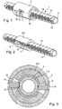
- Figure 1 shows a perspective view of a linear drive according to the invention.
- a cross-sectionally tubular rail 1 is longitudinally displaceable in arranged in a tubular housing 2.
- the rail 1 is through a tube 3 educated.
- Along the tube 3 are several arranged one behind the other Permanent magnets 4 arranged, which form secondary parts.
- FIG. 2 shows the linear drive according to the invention, but the housing 2 omitted. From this figure it can be seen that two circular segment-shaped Primary parts 5 are provided by several with an electric current actable coils 6 are formed. The primary parts 5 are in the circumferential direction arranged at a circumferential distance from each other, being in the distance range 7 a measuring head 8 of a length measuring system and a braking device 9 are arranged. The measuring head 8 and the braking device 9 are arranged in recesses 10, 11 of the housing 2, as shown in the figure 1 can be seen. It can also be seen from FIG. 1 that between these Recesses 10, 11 on the housing 2 a receptacle 12 for a no further Shown gimbal for the gimbal suspension of the linear drive is provided.
- FIGS. 1 to 3 there are two bowl-shaped ones Permanent magnets 4 lie on the circumference of the tube 3 are arranged. Between these pairs of permanent magnets are distance areas 13, as shown in FIG. 2.
- a material measure 14 is provided, which is arranged parallel to the longitudinal axis of the tube 3, and which only is attached to the pipe 3 at one point.
- This material measure 14 works with the above-mentioned measuring head 8 together, so that a length measuring system is formed to a relative displacement between the rail 1 and the To be able to measure housing 2.
- An evaluation unit, converter, etc. are here not explained in more detail.
- grooves 15 are introduced into the tube 3 parallel to the longitudinal axis of the tube, such as this can be seen particularly clearly in FIG. 4.
- the two ball grooves 18 of a pair of ball grooves are mirror-symmetrical to a plane arranged, which runs parallel to the rail 1, wherein in the embodiment the longitudinal axis of the tube 3 lies in this plane.
- This braking device 9 is in the Figure 4 also clearly shown. It comprises a brake caliper 19, which in the recess 10 of the housing 2 is attached.
- a brake piston 20 slidably arranged, the brake piston 20 on its end protruding from the brake caliper 19 with a brake pad 21 is provided.
- the brake pad 21 engages between two rows of balls that are formed by balls 17 of one or more ball circulation units 16.
- the Brake pad 21 works together with a brake track 22, which is parallel extends to the longitudinal axis of the rail 1, the groove base 23 of the groove 15 Brake track 22 forms.
- the brake piston 20 can be electrical, pneumatic, hydraulic or be subjected to mechanical loads. If the brake piston 20 is applied, the brake pad 21 engages the brake track 22 by one Relative movement between the rail 1 and the housing 2 quickly to stop.
- the braking device 9 is actuated automatically when the power is switched off, in other words when the linear drive is de-energized or when an emergency stop switch is actuated.
- Linear drive differs from the linear drive described above in Essentially in that instead of a rail 1 with a tubular cross section a rail 24 is formed with a square cross section. At this Rail 24 are formed on the circumference of four flat surfaces that are parallel to Longitudinal axis of the rail 24 are formed. Can advantageously commercially available flat permanent magnets 25 applied to these surfaces become. Instead of the permanent magnets, other secondary parts can also be used are used. In the corner areas of the rail 24 - where two mutually adjacent, mutually perpendicular surfaces of the rail 24 intersect - the rail 24 is provided with chamfers 26.
- a ball recirculation unit 27 only hinted at the housing 2 is attached.
- the balls of the recirculating ball unit, not shown 27 roll on a chamfer 26 designed as a ball groove 28.
Landscapes
- Engineering & Computer Science (AREA)
- Power Engineering (AREA)
- Physics & Mathematics (AREA)
- Chemical & Material Sciences (AREA)
- Combustion & Propulsion (AREA)
- Electromagnetism (AREA)
- Bearings For Parts Moving Linearly (AREA)
- Linear Motors (AREA)
Abstract
Description
- Figur 1
- eine perspektivische Darstellung eines erfindungsgemäßen Linearantriebs,
- Figur 2
- den Linearantrieb aus Figur 1, jedoch ohne Gehäuse,
- Figur 3
- einen Querschnitt durch den erfindungsgemäßen Linearantrieb aus Figur 1,
- Figur 4
- eine Ausschnittsvergrößerung des in Figur 5 abgebildeten Querschnitts und
- Figur 5
- einen weiteren erfindungsgemäßen Linearantrieb in perspektivischer Darstellung.
- 1
- Schiene
- 2
- Gehäuse
- 3
- Rohr
- 4
- Permanentmagnet
- 5
- Primärteil
- 6
- Spule
- 7
- Abstandsbereich
- 8
- Messkopf
- 9
- Bremseinrichtung
- 10
- Ausnehmung
- 11
- Ausnehmung
- 12
- Aufnahme
- 13
- Abstandsbereich
- 14
- Maßverkörperung
- 15
- Nut
- 16
- Kugelumlaufeinheit
- 17
- Kugel
- 18
- Kugelrille
- 19
- Bremssattel
- 20
- Bremskolben
- 21
- Bremsbelag
- 22
- Bremsbahn
- 23
- Nutgrund
- 24
- Schiene
- 25
- Primärteil
- 26
- Fase
- 27
- Kugelumlaufeinheit
- 28
- Kugelrille
Claims (12)
- Linearantrieb mit einem Gehäuse (2) und mit einer Schiene (1, 24), die an dem Gehäuse (2) bewegbar gelagert ist, und mit an dem Gehäuse (2) und an der Schiene (1, 24) vorgesehenen Antriebselementen (4, 5, 6, 25) zur Erzeugung einer Relativbewegung zwischen dem Gehäuse (2) und der Schiene (1, 24), dadurch gekennzeichnet, dass das Gehäuse (2) eine Bremseinrichtung (9) für das Zusammenwirken mit einer an der Schiene (1, 24) vorgesehenen Bremsbahn (22) aufweist.
- Linearantrieb nach Anspruch 1, bei dem die Schiene (1, 24) über Wälzlager (16, 27) an dem Gehäuse (2) gelagert ist, wobei entlang der Schiene (1, 24) Laufbahnen (18, 28) für Wälzkörper (17) vorgesehen sind, und wobei die Bremsbahn (22) parallel zur Laufbahn (18, 28) angeordnet ist.
- Linearantrieb nach Anspruch 2, bei dem die Bremsbahn (22) innerhalb der Laufbahn (18, 28) angeordnet ist.
- Linearantrieb nach Anspruch 3, bei dem innerhalb der Laufbahn (18, 28) und parallel zu ihr eine Nut (15) in der Schiene (1) vorgesehen ist, wobei die Bremsbahn (22) an der Nutwandung gebildet ist.
- Linearantrieb nach Antrieb 3, bei dem entlang der Schiene (1) eine Nut (15) ausgebildet ist, wobei die Seitenwände als Kugelrille (18) ausgebildet sind, und wobei der Nutgrund (23) als Bremsbahn (22) ausgebildet ist.
- Linearantrieb nach Anspruch 1, bei dem eine Längenmesseinrichtung vorgesehen ist, die einen an dem Gehäuse (1) vorgesehenen Messkopf (8) und eine an der Schiene (1) vorgesehene Maßverkörperung (14) umfasst.
- Linearantrieb nach Anspruch 1, bei dem die Bremseinrichtung (9) einen Bremssattel (19) umfasst, der einen mit einem Bremsbelag (21) versehenen Bremskolben (20) trägt.
- Linearantrieb nach Anspruch 1, bei der eine Baueinheit gebildet ist, bei der das Gehäuse (2) die Bremseinrichtung (9), einen Messkopf (8) einer Längenmesseinrichtung und Wälzkörperumlaufeinheiten (16, 27) zur Lagerung der Schiene (1) an dem Gehäuse (2) aufweist.
- Linearantrieb nach Anspruch 8, bei dem das Gehäuse (2) rohrförmig ausgebildet ist und an seinem Innenumfang mit einem Primärteil (5), insbesondere eine von einem elektrischen Strom beaufschlagbare Erregerwicklung versehen ist.
- Linearantrieb nach Anspruch 9, bei dem mehrere Primärteile (5) in Umfangsrichtung mit umfangsseitigem Abstand zueinander angeordnet sind, wobei in dem Abstandsbereich (13) der Messkopf (8), die Bremseinrichtung (9) und die Wälzkörperumlaufeinheiten (16, 27) untergebracht sind.
- Linearantrieb nach Anspruch 1, bei dem die Schiene (1) ein rohrförmiges Querschnittsprofil aufweist, wobei auf dem Außenumfang der Schiene (1) das insbesondere durch Permanentmagnete (4) gebildete Sekundärteil angebracht sind.
- Linearantrieb nach den Ansprüchen 2 und 11, bei dem mehrere Sekundärteile in Umfangsrichtung mit umfangsseitigem Abstand zueinander angeordnet sind, wobei in dem Abstandsbereich (7) die Bremsbahn (22) für die Bremseinrichtung (9) und die Laufbahnen (18, 28) für die Wälzkörper (17) angeordnet sind.
Applications Claiming Priority (2)
| Application Number | Priority Date | Filing Date | Title |
|---|---|---|---|
| DE10207697 | 2002-02-22 | ||
| DE10207697A DE10207697A1 (de) | 2002-02-22 | 2002-02-22 | Linearantrieb |
Publications (2)
| Publication Number | Publication Date |
|---|---|
| EP1339161A2 true EP1339161A2 (de) | 2003-08-27 |
| EP1339161A3 EP1339161A3 (de) | 2005-03-16 |
Family
ID=27635255
Family Applications (1)
| Application Number | Title | Priority Date | Filing Date |
|---|---|---|---|
| EP03001690A Withdrawn EP1339161A3 (de) | 2002-02-22 | 2003-01-25 | Linearantrieb |
Country Status (3)
| Country | Link |
|---|---|
| US (1) | US6915881B2 (de) |
| EP (1) | EP1339161A3 (de) |
| DE (1) | DE10207697A1 (de) |
Families Citing this family (4)
| Publication number | Priority date | Publication date | Assignee | Title |
|---|---|---|---|---|
| DE102009017549A1 (de) * | 2009-04-17 | 2010-10-21 | Zollern Maschinenbauelemente Gmbh & Co.Kg | Linearmotor |
| KR101077368B1 (ko) * | 2009-07-24 | 2011-10-27 | 삼성전기주식회사 | 선형 진동 장치 |
| US10056815B2 (en) * | 2014-09-30 | 2018-08-21 | Baker Hughes, A Ge Company, Llc | Linear drive system for downhole applications |
| CN105215765B (zh) * | 2015-10-08 | 2017-06-30 | 四川大学 | 一种管状体表面加工装置 |
Family Cites Families (14)
| Publication number | Priority date | Publication date | Assignee | Title |
|---|---|---|---|---|
| US2959695A (en) * | 1958-12-31 | 1960-11-08 | Lear Inc | Magnetic motor pole piece radial brake |
| DE8614673U1 (de) * | 1986-05-30 | 1987-10-15 | Robert Bosch Gmbh, 7000 Stuttgart | Lineareinheit für Handhabungsgeräte |
| JPH0624574Y2 (ja) | 1988-11-09 | 1994-06-29 | 日本精工株式会社 | クランプ装置付リニアガイド装置 |
| JP2607700B2 (ja) * | 1989-10-26 | 1997-05-07 | 動力炉・核燃料開発事業団 | 垂直搬送装置 |
| JPH0710095Y2 (ja) * | 1990-06-29 | 1995-03-08 | 日本トムソン株式会社 | 防振性を有する直動転がり案内ユニット |
| DE4116795C2 (de) * | 1991-05-23 | 1998-09-03 | Schaeffler Waelzlager Ohg | Klemmvorrichtung für einen entlang einer oder mehrerer Führungsschienen bewegbaren Tisch oder dergleichen |
| JP3682102B2 (ja) | 1995-11-22 | 2005-08-10 | 日本トムソン株式会社 | 直動クランプユニット |
| JPH1089357A (ja) * | 1996-09-10 | 1998-04-07 | Nippon Thompson Co Ltd | 直動案内装置用の制動装置 |
| EP0861990B1 (de) * | 1997-02-28 | 2004-08-18 | Deutsche Star GmbH | Linearführungseinrichtung |
| DE19715014A1 (de) * | 1997-04-11 | 1998-10-15 | Schaeffler Waelzlager Ohg | Linearführung |
| DE19806832A1 (de) * | 1998-02-18 | 1999-08-26 | Fraunhofer Ges Forschung | Linearantrieb |
| US6179468B1 (en) * | 1998-08-20 | 2001-01-30 | Dale Thorstens | Plain bearing brake-tensioner |
| DE20002915U1 (de) * | 2000-02-18 | 2000-08-10 | Zimmer Guenther Stephan | Brems- und/oder Klemmvorrichtung für Führungen |
| DE20007499U1 (de) * | 2000-04-26 | 2000-10-05 | Zimmer Guenther Stephan | Brems- und/oder Klemmvorrichtung für Führungen |
-
2002
- 2002-02-22 DE DE10207697A patent/DE10207697A1/de not_active Ceased
-
2003
- 2003-01-25 EP EP03001690A patent/EP1339161A3/de not_active Withdrawn
- 2003-02-21 US US10/372,601 patent/US6915881B2/en not_active Expired - Fee Related
Also Published As
| Publication number | Publication date |
|---|---|
| DE10207697A1 (de) | 2003-09-04 |
| US6915881B2 (en) | 2005-07-12 |
| US20030173162A1 (en) | 2003-09-18 |
| EP1339161A3 (de) | 2005-03-16 |
Similar Documents
| Publication | Publication Date | Title |
|---|---|---|
| EP2712412B1 (de) | Elektromechanischer linearantrieb mit nachschmiereinrichtung | |
| DE102013020490A1 (de) | Antriebsvorrichtung für eine Greifvorrichtung | |
| EP0774592B1 (de) | Linearführung | |
| DE4301434C2 (de) | Linearführungsanordnung mit Ausgleichsmitteln für mechanische Spannungen | |
| EP2299141A2 (de) | Brems- und/oder Klemmvorrichtung mit formsteifem Zentralkörper | |
| DE10219988A1 (de) | Direktantriebslagermechanismus | |
| DE102011014079A1 (de) | Radiales Mehrpunktlager mit axialer Loslagerfunktion für hohe Drehzahlen | |
| DE202016101698U1 (de) | Gleitlager, Gleitführung und Gleitelement für eine Kurvenschiene | |
| DE19605388C2 (de) | Linearführung | |
| DE102019108235A1 (de) | Lenkungsaktuator | |
| DE102013226826A1 (de) | Linearmotoranordnung und Werkzeugmaschine mit einer Linearmotoranordnung | |
| EP1056566A1 (de) | Linearantrieb | |
| DE102011080749B4 (de) | Profilschienenwagen, Profilschiene und Profilschienenführung | |
| EP0171700B1 (de) | Einstellbare Wälzkörperumlauf-Geradführung | |
| DE10207697A1 (de) | Linearantrieb | |
| DE202009012485U1 (de) | Linearachse | |
| DE4410159A1 (de) | Linearführungseinheit | |
| DE102010051268A1 (de) | Elektromechanische Fahrzeuglenkung mit Kugelgewindetrieb | |
| EP1512878B1 (de) | Linearführung | |
| CH693071A5 (de) | Gleitlager. | |
| DE19920264A1 (de) | Werkzeugaufnahme für eine Schnellfrequenzspindel | |
| DE102010010730A1 (de) | Hubvorichtung einer Liegevorrichtung, bespielsweise einer Patientenliege | |
| EP2063503A2 (de) | Crimppresse | |
| EP1350963A2 (de) | Teleskopische Schiene | |
| DE1909845U (de) | Rollen-flachkafig. |
Legal Events
| Date | Code | Title | Description |
|---|---|---|---|
| PUAI | Public reference made under article 153(3) epc to a published international application that has entered the european phase |
Free format text: ORIGINAL CODE: 0009012 |
|
| 17P | Request for examination filed |
Effective date: 20030125 |
|
| AK | Designated contracting states |
Designated state(s): AT BE BG CH CY CZ DE DK EE ES FI FR GB GR HU IE IT LI LU MC NL PT SE SI SK TR |
|
| AX | Request for extension of the european patent |
Extension state: AL LT LV MK RO |
|
| PUAL | Search report despatched |
Free format text: ORIGINAL CODE: 0009013 |
|
| AK | Designated contracting states |
Kind code of ref document: A3 Designated state(s): AT BE BG CH CY CZ DE DK EE ES FI FR GB GR HU IE IT LI LU MC NL PT SE SI SK TR |
|
| AX | Request for extension of the european patent |
Extension state: AL LT LV MK RO |
|
| AKX | Designation fees paid |
Designated state(s): DE FR IT SE |
|
| RAP1 | Party data changed (applicant data changed or rights of an application transferred) |
Owner name: SCHAEFFLER KG |
|
| STAA | Information on the status of an ep patent application or granted ep patent |
Free format text: STATUS: THE APPLICATION IS DEEMED TO BE WITHDRAWN |
|
| 18D | Application deemed to be withdrawn |
Effective date: 20060719 |
|
| P01 | Opt-out of the competence of the unified patent court (upc) registered |
Effective date: 20230524 |