EP1338793A2 - Bord de fuite cranelée pour pale d'éolienne - Google Patents
Bord de fuite cranelée pour pale d'éolienne Download PDFInfo
- Publication number
- EP1338793A2 EP1338793A2 EP03003852A EP03003852A EP1338793A2 EP 1338793 A2 EP1338793 A2 EP 1338793A2 EP 03003852 A EP03003852 A EP 03003852A EP 03003852 A EP03003852 A EP 03003852A EP 1338793 A2 EP1338793 A2 EP 1338793A2
- Authority
- EP
- European Patent Office
- Prior art keywords
- blade
- wind turbine
- length
- trailing edge
- dentation
- Prior art date
- Legal status (The legal status is an assumption and is not a legal conclusion. Google has not performed a legal analysis and makes no representation as to the accuracy of the status listed.)
- Withdrawn
Links
- 229910052751 metal Inorganic materials 0.000 claims abstract description 37
- 239000002184 metal Substances 0.000 claims abstract description 37
- 230000003247 decreasing effect Effects 0.000 claims description 33
- 229910000838 Al alloy Inorganic materials 0.000 claims description 21
- 229910001069 Ti alloy Inorganic materials 0.000 claims description 15
- 230000007423 decrease Effects 0.000 claims description 15
- RTAQQCXQSZGOHL-UHFFFAOYSA-N Titanium Chemical compound [Ti] RTAQQCXQSZGOHL-UHFFFAOYSA-N 0.000 claims description 10
- XAGFODPZIPBFFR-UHFFFAOYSA-N aluminium Chemical compound [Al] XAGFODPZIPBFFR-UHFFFAOYSA-N 0.000 claims description 10
- 239000010959 steel Substances 0.000 claims description 10
- 239000010936 titanium Substances 0.000 claims description 10
- 229910052782 aluminium Inorganic materials 0.000 claims description 8
- 229910052719 titanium Inorganic materials 0.000 claims description 8
- 229910000831 Steel Inorganic materials 0.000 claims description 5
- 239000007787 solid Substances 0.000 claims description 5
- 238000003466 welding Methods 0.000 claims description 3
- 239000000463 material Substances 0.000 description 6
- 229920001875 Ebonite Polymers 0.000 description 5
- 230000000694 effects Effects 0.000 description 5
- 238000004519 manufacturing process Methods 0.000 description 4
- -1 polypropylene Polymers 0.000 description 4
- 229910000851 Alloy steel Inorganic materials 0.000 description 3
- 230000000737 periodic effect Effects 0.000 description 3
- 229910001200 Ferrotitanium Inorganic materials 0.000 description 2
- 238000005266 casting Methods 0.000 description 2
- 230000002787 reinforcement Effects 0.000 description 2
- 238000007493 shaping process Methods 0.000 description 2
- 230000001629 suppression Effects 0.000 description 2
- 229920002430 Fibre-reinforced plastic Polymers 0.000 description 1
- 229920000209 Hexadimethrine bromide Polymers 0.000 description 1
- 239000004743 Polypropylene Substances 0.000 description 1
- 229910045601 alloy Inorganic materials 0.000 description 1
- 239000000956 alloy Substances 0.000 description 1
- 238000005452 bending Methods 0.000 description 1
- 230000015572 biosynthetic process Effects 0.000 description 1
- 239000012141 concentrate Substances 0.000 description 1
- 239000000470 constituent Substances 0.000 description 1
- 238000010276 construction Methods 0.000 description 1
- 239000011151 fibre-reinforced plastic Substances 0.000 description 1
- 150000002739 metals Chemical class 0.000 description 1
- 239000000203 mixture Substances 0.000 description 1
- 229920001155 polypropylene Polymers 0.000 description 1
- 238000010248 power generation Methods 0.000 description 1
- 229920005989 resin Polymers 0.000 description 1
- 239000011347 resin Substances 0.000 description 1
- 238000010008 shearing Methods 0.000 description 1
Images


Classifications
-
- F—MECHANICAL ENGINEERING; LIGHTING; HEATING; WEAPONS; BLASTING
- F03—MACHINES OR ENGINES FOR LIQUIDS; WIND, SPRING, OR WEIGHT MOTORS; PRODUCING MECHANICAL POWER OR A REACTIVE PROPULSIVE THRUST, NOT OTHERWISE PROVIDED FOR
- F03D—WIND MOTORS
- F03D1/00—Wind motors with rotation axis substantially parallel to the air flow entering the rotor
- F03D1/06—Rotors
- F03D1/065—Rotors characterised by their construction elements
-
- F—MECHANICAL ENGINEERING; LIGHTING; HEATING; WEAPONS; BLASTING
- F03—MACHINES OR ENGINES FOR LIQUIDS; WIND, SPRING, OR WEIGHT MOTORS; PRODUCING MECHANICAL POWER OR A REACTIVE PROPULSIVE THRUST, NOT OTHERWISE PROVIDED FOR
- F03D—WIND MOTORS
- F03D1/00—Wind motors with rotation axis substantially parallel to the air flow entering the rotor
- F03D1/06—Rotors
- F03D1/0608—Rotors characterised by their aerodynamic shape
- F03D1/0633—Rotors characterised by their aerodynamic shape of the blades
- F03D1/0641—Rotors characterised by their aerodynamic shape of the blades of the section profile of the blades, i.e. aerofoil profile
-
- F—MECHANICAL ENGINEERING; LIGHTING; HEATING; WEAPONS; BLASTING
- F05—INDEXING SCHEMES RELATING TO ENGINES OR PUMPS IN VARIOUS SUBCLASSES OF CLASSES F01-F04
- F05B—INDEXING SCHEME RELATING TO WIND, SPRING, WEIGHT, INERTIA OR LIKE MOTORS, TO MACHINES OR ENGINES FOR LIQUIDS COVERED BY SUBCLASSES F03B, F03D AND F03G
- F05B2240/00—Components
- F05B2240/20—Rotors
- F05B2240/30—Characteristics of rotor blades, i.e. of any element transforming dynamic fluid energy to or from rotational energy and being attached to a rotor
-
- F—MECHANICAL ENGINEERING; LIGHTING; HEATING; WEAPONS; BLASTING
- F05—INDEXING SCHEMES RELATING TO ENGINES OR PUMPS IN VARIOUS SUBCLASSES OF CLASSES F01-F04
- F05B—INDEXING SCHEME RELATING TO WIND, SPRING, WEIGHT, INERTIA OR LIKE MOTORS, TO MACHINES OR ENGINES FOR LIQUIDS COVERED BY SUBCLASSES F03B, F03D AND F03G
- F05B2250/00—Geometry
- F05B2250/10—Geometry two-dimensional
- F05B2250/11—Geometry two-dimensional triangular
-
- F—MECHANICAL ENGINEERING; LIGHTING; HEATING; WEAPONS; BLASTING
- F05—INDEXING SCHEMES RELATING TO ENGINES OR PUMPS IN VARIOUS SUBCLASSES OF CLASSES F01-F04
- F05B—INDEXING SCHEME RELATING TO WIND, SPRING, WEIGHT, INERTIA OR LIKE MOTORS, TO MACHINES OR ENGINES FOR LIQUIDS COVERED BY SUBCLASSES F03B, F03D AND F03G
- F05B2250/00—Geometry
- F05B2250/10—Geometry two-dimensional
- F05B2250/13—Geometry two-dimensional trapezial
-
- F—MECHANICAL ENGINEERING; LIGHTING; HEATING; WEAPONS; BLASTING
- F05—INDEXING SCHEMES RELATING TO ENGINES OR PUMPS IN VARIOUS SUBCLASSES OF CLASSES F01-F04
- F05B—INDEXING SCHEME RELATING TO WIND, SPRING, WEIGHT, INERTIA OR LIKE MOTORS, TO MACHINES OR ENGINES FOR LIQUIDS COVERED BY SUBCLASSES F03B, F03D AND F03G
- F05B2250/00—Geometry
- F05B2250/10—Geometry two-dimensional
- F05B2250/18—Geometry two-dimensional patterned
- F05B2250/181—Geometry two-dimensional patterned ridged
-
- F—MECHANICAL ENGINEERING; LIGHTING; HEATING; WEAPONS; BLASTING
- F05—INDEXING SCHEMES RELATING TO ENGINES OR PUMPS IN VARIOUS SUBCLASSES OF CLASSES F01-F04
- F05B—INDEXING SCHEME RELATING TO WIND, SPRING, WEIGHT, INERTIA OR LIKE MOTORS, TO MACHINES OR ENGINES FOR LIQUIDS COVERED BY SUBCLASSES F03B, F03D AND F03G
- F05B2250/00—Geometry
- F05B2250/10—Geometry two-dimensional
- F05B2250/18—Geometry two-dimensional patterned
- F05B2250/183—Geometry two-dimensional patterned zigzag
-
- F—MECHANICAL ENGINEERING; LIGHTING; HEATING; WEAPONS; BLASTING
- F05—INDEXING SCHEMES RELATING TO ENGINES OR PUMPS IN VARIOUS SUBCLASSES OF CLASSES F01-F04
- F05B—INDEXING SCHEME RELATING TO WIND, SPRING, WEIGHT, INERTIA OR LIKE MOTORS, TO MACHINES OR ENGINES FOR LIQUIDS COVERED BY SUBCLASSES F03B, F03D AND F03G
- F05B2260/00—Function
- F05B2260/96—Preventing, counteracting or reducing vibration or noise
-
- F—MECHANICAL ENGINEERING; LIGHTING; HEATING; WEAPONS; BLASTING
- F05—INDEXING SCHEMES RELATING TO ENGINES OR PUMPS IN VARIOUS SUBCLASSES OF CLASSES F01-F04
- F05B—INDEXING SCHEME RELATING TO WIND, SPRING, WEIGHT, INERTIA OR LIKE MOTORS, TO MACHINES OR ENGINES FOR LIQUIDS COVERED BY SUBCLASSES F03B, F03D AND F03G
- F05B2280/00—Materials; Properties thereof
- F05B2280/10—Inorganic materials, e.g. metals
- F05B2280/102—Light metals
- F05B2280/1021—Aluminium
-
- F—MECHANICAL ENGINEERING; LIGHTING; HEATING; WEAPONS; BLASTING
- F05—INDEXING SCHEMES RELATING TO ENGINES OR PUMPS IN VARIOUS SUBCLASSES OF CLASSES F01-F04
- F05B—INDEXING SCHEME RELATING TO WIND, SPRING, WEIGHT, INERTIA OR LIKE MOTORS, TO MACHINES OR ENGINES FOR LIQUIDS COVERED BY SUBCLASSES F03B, F03D AND F03G
- F05B2280/00—Materials; Properties thereof
- F05B2280/10—Inorganic materials, e.g. metals
- F05B2280/103—Heavy metals
- F05B2280/10304—Titanium
-
- F—MECHANICAL ENGINEERING; LIGHTING; HEATING; WEAPONS; BLASTING
- F05—INDEXING SCHEMES RELATING TO ENGINES OR PUMPS IN VARIOUS SUBCLASSES OF CLASSES F01-F04
- F05B—INDEXING SCHEME RELATING TO WIND, SPRING, WEIGHT, INERTIA OR LIKE MOTORS, TO MACHINES OR ENGINES FOR LIQUIDS COVERED BY SUBCLASSES F03B, F03D AND F03G
- F05B2280/00—Materials; Properties thereof
- F05B2280/10—Inorganic materials, e.g. metals
- F05B2280/107—Alloys
- F05B2280/1071—Steel alloys
-
- F—MECHANICAL ENGINEERING; LIGHTING; HEATING; WEAPONS; BLASTING
- F05—INDEXING SCHEMES RELATING TO ENGINES OR PUMPS IN VARIOUS SUBCLASSES OF CLASSES F01-F04
- F05C—INDEXING SCHEME RELATING TO MATERIALS, MATERIAL PROPERTIES OR MATERIAL CHARACTERISTICS FOR MACHINES, ENGINES OR PUMPS OTHER THAN NON-POSITIVE-DISPLACEMENT MACHINES OR ENGINES
- F05C2201/00—Metals
- F05C2201/02—Light metals
- F05C2201/021—Aluminium
-
- F—MECHANICAL ENGINEERING; LIGHTING; HEATING; WEAPONS; BLASTING
- F05—INDEXING SCHEMES RELATING TO ENGINES OR PUMPS IN VARIOUS SUBCLASSES OF CLASSES F01-F04
- F05C—INDEXING SCHEME RELATING TO MATERIALS, MATERIAL PROPERTIES OR MATERIAL CHARACTERISTICS FOR MACHINES, ENGINES OR PUMPS OTHER THAN NON-POSITIVE-DISPLACEMENT MACHINES OR ENGINES
- F05C2201/00—Metals
- F05C2201/04—Heavy metals
- F05C2201/0403—Refractory metals, e.g. V, W
- F05C2201/0412—Titanium
-
- F—MECHANICAL ENGINEERING; LIGHTING; HEATING; WEAPONS; BLASTING
- F05—INDEXING SCHEMES RELATING TO ENGINES OR PUMPS IN VARIOUS SUBCLASSES OF CLASSES F01-F04
- F05C—INDEXING SCHEME RELATING TO MATERIALS, MATERIAL PROPERTIES OR MATERIAL CHARACTERISTICS FOR MACHINES, ENGINES OR PUMPS OTHER THAN NON-POSITIVE-DISPLACEMENT MACHINES OR ENGINES
- F05C2201/00—Metals
- F05C2201/04—Heavy metals
- F05C2201/0433—Iron group; Ferrous alloys, e.g. steel
- F05C2201/0448—Steel
-
- F—MECHANICAL ENGINEERING; LIGHTING; HEATING; WEAPONS; BLASTING
- F05—INDEXING SCHEMES RELATING TO ENGINES OR PUMPS IN VARIOUS SUBCLASSES OF CLASSES F01-F04
- F05C—INDEXING SCHEME RELATING TO MATERIALS, MATERIAL PROPERTIES OR MATERIAL CHARACTERISTICS FOR MACHINES, ENGINES OR PUMPS OTHER THAN NON-POSITIVE-DISPLACEMENT MACHINES OR ENGINES
- F05C2201/00—Metals
- F05C2201/90—Alloys not otherwise provided for
- F05C2201/903—Aluminium alloy, e.g. AlCuMgPb F34,37
-
- Y—GENERAL TAGGING OF NEW TECHNOLOGICAL DEVELOPMENTS; GENERAL TAGGING OF CROSS-SECTIONAL TECHNOLOGIES SPANNING OVER SEVERAL SECTIONS OF THE IPC; TECHNICAL SUBJECTS COVERED BY FORMER USPC CROSS-REFERENCE ART COLLECTIONS [XRACs] AND DIGESTS
- Y02—TECHNOLOGIES OR APPLICATIONS FOR MITIGATION OR ADAPTATION AGAINST CLIMATE CHANGE
- Y02E—REDUCTION OF GREENHOUSE GAS [GHG] EMISSIONS, RELATED TO ENERGY GENERATION, TRANSMISSION OR DISTRIBUTION
- Y02E10/00—Energy generation through renewable energy sources
- Y02E10/70—Wind energy
- Y02E10/72—Wind turbines with rotation axis in wind direction
Definitions
- the present invention relates to a wind turbine provided with a nacelle, in which dentation such as serration of triangular tooth or trapezoid tooth is formed in the trailing edge part of each of the blades of the turbine along the length of the blade.
- wind turbine generator equipment having large electric power generation capacity have been established at high elevations such as on hills and mountains or on the sea where high wind speed can be utilized, the equipment comprising a number of large wind turbine generating units, each wind turbine being provided with a nacelle and generating rotating force by the wind force acting on a plurality of blades attached to the rotor to drive an electric generator connected to the rotor.
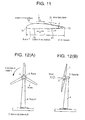
- FIG.12 An example of a horizontal-axis wind turbine provided with a nacelle will be explained with reference to FIG.12.
- the wind turbine is mounted on the top of a tapered tube-like tower(support) 4 made of, for example, steel or concrete for revolution in a horizontal plane via a nacelle(box for accommodating apparatuses) 5, the horizontal drive shaft 3 of a rotor 2 having three blades 1 in front of the nacelle 5 is supported by the nacelle 5.
- Said horizontal drive shaft 3 is connected to an electric generator(not shown in the drawing) via a speed increasing gearbox (not shown in the drawing) in the nacelle 5.
- the diameter of the surface of revolution of blade of a conventional large horizontal-axis wind turbine reaches near 45m
- the wind turbine to which the present invention is applied can be composed to have the diameter of the surface of revolution of blade of 10m to 100m, not limited to near 45m.
- FIG.13 shows an example of the blade of prior art of a conventional wind turbine provided with a nacelle, (A) is a partially perspective view, (B) is a sectional view, and (C) is an enlarged partially plan view of the trailing edge part of the blade.
- reference numeral 1 is a blade
- 11 is the leading edge part
- 12 is the trailing edge part
- 1a is the upper chord surface
- 1b is the lower chord surface of the blade 1.
- the sectional profile of the blade of said wind turbine is of a streamlined one, a profile so-called an airfoil, which is tapered off to the rear edge (trailing edge) and less subjected to air resistance, and rotating force results from the lift F effected through the pressure difference arising from the difference between the velocities of air stream S on the lower chord surface 1b andupper chord surface 1a of the blade 1.
- Said blade 1 is made of FRP(fiber reinforced plastic) into one-piece structure or may be made of porous resin such as foamed polypropylene (polybrene) in the case of a small size blade.
- a wind turbine blade consisting of a main blade body part and a rear end part is proposed in Japanese Patent Application Publication 2000-120524, in which said rear end part is formed as a separate member and fixed to said main blade body, and the rear end member constituting said rear end part has a plurality of protrusions of triangular or sawtooth-like tooth formed along the length of the blade in its trailing edge part and extending toward the rear.
- the rear end member of the wind turbine blade is formed as a separate member and fixed to the main blade body, the rear end member can be worked separately, and the working thereof becomes easy as the handling of the whole of the large blade is not necessary.
- the disclosure describes that by forming the rear end member with high precision the thickness of the trailing edge can be reduced to such a value as the generation of Karman vortex street is suppressed, and further that vortexes which interfere the generation of said Karman vortex street are generated owing to the protrusions of triangular or sawtooth-like teeth formed in the trailing edge part along the length of the trailing edge part of the separate rear end member and extending toward the rear, and as a result noise level is reduced.
- the trailing edge part is liable to be fractured by stress concentration as the thickness thereof is necessary to be thin.
- the front end part and the rear end part of the blade are composed of a plurality of separate members respectively and each separate member can be deformed independently.
- this composition the concentration of stress is alleviated and fracture due to stress concentration is prevented.
- the rear end part of the wind turbine blade having dentation of triangular or trapezoid tooth formed in the trailing edge part is formed into a separate member or a plurality of separate members made of hard rubber which is tenacious than the FRP of the main blade body and fixed to the rear end of the main blade body.
- Karman vortex street 19 consisting of a couple of vortex sheets is developed downstream from the trailing edge, the vortex being generated periodically with a cycle proportional to wind speed, and the couple of vortex streets A, A1 proceed downstream to B, B1 as shown in FIG. 13 (A). Noise of frequency proportional to wind speed is generated caused by this phenomenon.
- the thickness t of trailing edge of the blade 1 is inevitably relatively large because the sheet of FRP joins at the trailing edge, and it is difficult to suppress the generation of said Karman vortex street 19 completely.
- a blade surface boundary layer 21 is formed between air stream S and the surface of the blade 1, i.e. the upper chord surface 1a and lower chord surface 1b as shown in FIG.13(B) owing to the construction that a FRP sheet surrounds the vicinity of the trailing edge part.
- the blade surface boundary layer 21 influences largely upon the performance of the blade 1.
- the thickness ⁇ of the boundary layer 21 increases, the flow loss due to the development of the boundary layer increases and blade performance is decreased.
- the blade surface boundary layer is a thin layer of air developed on the surface of blade due to the viscosity of air, a thin layer from the surface(where the velocity of air relative to the blade surface is zero) to the place where the velocity of air relative to the blade surface is the same or near the relative velocity of the air stream S outside the boundary layer.
- the thickness ⁇ of boundary layer is proportional to the chord length L.
- the thickness ⁇ of the boundary layer 21 decreases with decreasing chord length L, and blade performance is increased by decreasing chord length L. But, with the blade of said prior art made of FRP in which a FRP sheet surrounds the vicinity of the trailing edge part, there is a limit to decrease the thickness ⁇ of the boundary layer 21.
- the blade 1 which allows the formation of the blade surface boundary layer 21 of thickness ⁇ with which good blade performance can be attained while taking into consideration the strength and output(lift) of the blade 1.
- Karman vortex street 19 is generated and proceeds downstream from the trailing edge 12 as shown in FIG.13(A), and the noise of frequency proportional to the wind speed is generated in the rear near the trailing edge 12.
- the blade 1 having rear end member made of hard rubber fixed to the rear end of the main blade body as disclosed in Japanese Patent Application Publication 2000-120524, the strength of the trailing edge part 12 is low compared with that of the main blade body, and it is difficult to provide such a blade as is capable of suppressing the generation of said Karman vortex street 19.
- the present invention was made in light of the problems mentioned above, and an object of the invention is to provide a wind turbine provided with a nacelle, which has blades strong enough for sporadic heavy load, is highly durable and reliable, is capable of being increased in performance by making it possible to reduce blade thickness, and can suppress the generation of the noise due to Karman vortex street.
- Another object of the invention is to provide a wind turbine provided with a nacelle, of which each blade is formed so that the thickness of the boundary layer generated on the chord surface becomes such a thickness as to be able to attain good blade performance.
- the present invention was made to attain these object, and proposes a wind turbine provided with a nacelle mounted on the top end of a support for horizontal revolution, a rotor having a plurality of blades in front of the nacelle being supported for rotation by the nacelle, rotating force being resulted from the lift effected through the pressure difference arising from the difference between the velocities of air stream on the lower chord surface and upper chord surface of the blades, wherein each of said blades is a one-piece blade made of one kind of metal or the rear end part of the blade is made of another metal, and the trailing edge part of the blade is formed to have dentation along the length of the blade.
- the one-piece blade is made of light metal such as aluminum, titanium, or aluminum alloy including titanium, and when the blade is of split-type, the main part (main blade body) of said blade excluding the rear end part of the blade is made of one kind of light metal, and the rear end part is made of another metal having higher strength than the metal of said main blade body, concretively, said main blade body is made of aluminum or aluminum alloy, and said rear end part is made of titanium or steel.
- said main blade body is formed into a hollow one
- said rear end part is formed into a solid one
- the both are connected by means of rivet or by welding.
- the blade can be formed into a thin blade as a whole while maintaining the strength of the blade, as the one-piece blade or the main blade body of the split-type blade is made of high-strength metal, preferably aluminum alloy including high-strength aluminum.
- the trailing edge of the blade can be reduced to about 2mm.
- the generation of Karman vortex street can be completely prevented by forming dentation in the trailing edge part of the blade along the length of the blade, and the noise due to the generation of Karman vortex street is positively suppressed.
- the strength of the blade is secured, for the rear end part of the blade is made of high-strength metal such as titanium or steel. Therefore, a thin, lightweight blade which has enough strength for sporadic heavy load which may act on the blade when a gust of wind or earthquake occurs, can be obtained.
- the blade having high durability and reliability is provided with which the damage of blade when such heavy load acts on the blade is evaded.
- the one-piece blade or the main blade body is made of high-strength light metal, required blade strength can be secured even when the blade or main blade body is made of one kind of metal, and the provision of core members in the blade for reinforcement is not necessary as is in the case of the conventional blade made of FRP. Accordingly, the structure of the blade 1 is simplified.
- the blade 1 can be easily manufactured by press working or casting of aluminum alloy, and production man-hour is largely reduced.
- main blade body and rear end part are made of metals different from each other, it is possible to form the main blade body, which constitutes most of the weight of the blade, out of light metal such as aluminum alloy including aluminum or titanium alloy including titanium, and the rear end member, which constitutes a relatively small percentage of the weight of the blade, out of high-strength steel or titanium alloy which is easy to be formed into thin trailing edge part and also easy to be formed to have the dentation in the trailing edge part.
- the wind turbine blade can be obtained which can achieve increased blade performance and positively suppress the noise due to the generation of Karman vortex street.
- ratio h/ ⁇ The larger the ratio h/ ⁇ is, the better the effect of noise reduction.
- the values of ratio h/ ⁇ shown above are suitable in view of the meaningful effect on the airfoil characteristic and the strength of the tooth in consideration of the height-and-thickness relation thereof.
- tooth height h decreases toward the outer end of the blade along the length thereof so that said ratio(h/ ⁇ ) of the tooth height h to the thickness ⁇ of the boundary layer developed on the surface of the blade is constant along the length of the blade.
- the tooth height h is constant along the length of the blade and the chord length L of the blade is decreased toward the outer end of the blade along the length thereof so that said ratio(h/ ⁇ ) of the tooth height h to the thickness ⁇ of the boundary layer developed on the surface of the blade increases toward the end of the blade along the length thereof.
- the flow loss due to the blade surface boundary layer in the vicinity of the dentation is decreased and the performance of the blade is increased by increasing the ratio(h/ ⁇ ) of the tooth height h of the dentation to the thickness ⁇ of the blade surface boundary layer, that is, by increasing the tooth height h of the dentation or by decreasing the thickness ⁇ of the boundary layer.
- chord length L of the blade must inevitably be increased, so that the blade becomes larger and the thickness of the boundary layer rather increases due to the increase of the chord length L.
- the blade is composed so that the ratio(h/ ⁇ ) of the tooth height h of the dentation to the thickness ⁇ of the boundary layer is 1.0 ⁇ 10.0.
- the tooth height h is decreased toward the outer end of the blade along the length thereof so that the ratio (h/ ⁇ ) of the tooth height h of the dentation to the thickness ⁇ of the boundary layer is constant along the length of the blade, the flow loss owing to the blade surface boundary layer can be suppressed to a constant value along the length of the blade, and the tooth height h can be decreased in proportion to the chord length L along the length of the blade, resulting in a balanced blade strength and output(lift) along the length of the blade.
- the tooth height h of the dentation is constant along the length of the blade and the chord length L of the blade is decreased toward the outer end of the blade along the length thereof so that the ratio(h/ ⁇ ) of the tooth height h to the thickness ⁇ of the blade surface boundary layer increases toward the outer end of the blade along the length thereof, the flow loss due to the blade surface boundary layer is decreased toward the outer end of the blade, where the rotating force obtained from wind force is larger for increased radius from the center of rotaion axis of blade, and the blade can achieve high efficiency over the length of the blade with the chord length L of the blade determined to the minimum value for securing the strength of the blade.
- the blade is configured such that the dentation of the trailing edge part along the length of the blade is shaped in a serration of triangular tooth, of trapezoid tooth, or of sawtooth, and the ratio(h/p) of the tooth height h to the pitch p is 0.5 ⁇ 5.0.
- the tooth height h When the ratio(h/p) of the height h to pitch p of the tooth of the dentation is smaller than 0.5, the tooth height h must be small, the trailing edge of the rear end part approximates a flat trailing edge, and the generation of the longitudinal vortex tubes owing to the dentation and the consequent effect of suppressing the generation of Karman vortex street can not be expected.
- the ratio h/p is a parameter indicating the degree of protrusion of the tooth of the dentation, which exerts an influence upon the direction of the vortex lines starting from the dentation, and said range of the ratio h/p is most suitable for attaining noise reduction.
- the blade as mentioned above is suitable for applying to a large wind turbine provided with a nacelle of which the diameter of the surface of revolution of blades exceeds 10 m and reaches 100 m.
- FIG.12 represents schematically a horizontal-axis wind turbine, such that a nacelle 5 (box for accommodating apparatuses) is mounted on a support 4 for horizontal revolution and the horizontal drive shaft 3 of a rotor 2 having three blades 1 in front of the nacelle 5 is supported by the nacelle 5.
- the horizontal drive shaft 3 is connected to an electric generator(not shown in the drawing) via a speed increasing gearbox (not shown in the drawing) in the nacelle 5.
- the diameter of the surface of revolution of blade of said conventional large horizontal-axis wind turbine reaches near 45m
- the wind turbine to which the present invention is applied can be composed to have the diameter of the surface of revolution of blade of 10m to 100m, not limited to near 45m, which means that super large type horizontal-axis wind turbine can be realized by applying the present invention.
- the sectional profile of the blade of said wind turbine is of a streamlined one tapered off to the rear edge (trailing edge), which is less subjected to air resistance, and rotating force results from the lift F which is effected through the pressure difference arising from the difference between the velocities of air stream S on the lower chord surface 1b and upper chord surface 1a of the blade 1.
- the blade 1 is made of high-strength aluminum or aluminum alloy including rolled aluminum alloy or cast aluminum alloy into a single-piece blade. It is suitable to make the blade of high-strength light metal including titanium or titanium alloy.
- Reference numeral 11 is the leading edge part
- 12 is the trailing edge part.
- dentation 13 along the length of the blade 1.
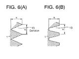
- the dentation 13 is formed in the shape of serration of triangular protrusions as shown in FIG. 6 (A) or serration of trapezoidal protrusions as shown in FIG. 6 (B) .
- the pitch p and height h of the teeth are determined in relation to the thickness t of the trailing edge of the trailing edge part 12 so that the generation of Karman vortex street is minimum.
- the shape of the dentation 13 is not limited to said serration of triangular protrusions or trapezoidal protrusions, any dentations which suppress the generation of Karman vortex street are suitable.
- the blade 1 may be formed into a solid, one-piece blade as shown in FIG.2, or into a hollow, one-piece blade as shown in FIG.3, in which reference numeral 14 denotes the cavity, for the reduction of weight.
- the blade 1 is made of light, high-strength metal such as aluminum alloy including high-strength aluminum, and formed into one-piece blade, so that the blade can be formed into a thin blade for reducing air resistance while securing enough strength of the blade. Therefore, the performance of the blade 1 can be largely improved by reducing the thickness of blade and increased efficiency of the wind turbine can be attained.
- the thickness of the trailing edge part 12 of the blade 1 can be reduced to a minimum(about 2mm) without problems.
- the dentation 13 induces the generation of non-periodic vortexes 17 rotating about the longitudinal lines parallel to the direction of wind and passing the tips and roots of the teeth as shown in FIG.1, and these vortexes 17 interfere with the generation of Karman vortex street resulting in the suppression of the noise induced by Karman vortex street.
- the trailing edge part 12 of the blade 1 by forming the trailing edge part 12 of the blade 1 to be thin to a minimum thickness (about 2mm) without affecting the strength of the blade1 and by forming the detention 13 in the trailing edge part 12, the generation of Karman vortex street downstream from the trailing edge 12 is completely prevented and the noise due to said Karman vortex street can be positively suppressed.
- the blade 1 As the blade 1 is formed into one-piece out of high-strength metal such as aluminum alloy or titanium alloy, the blade 1 can be made to have high strength even if it is formed into a thin blade profile. Therefore, the blade 1 can be made light in weight, strength enough for sporadic heavy load to the blade due to a gust of wind or earth quake can be secured by the thin, lightweight blade, and the damage of the blade 1 when such heavy load acts on the blade is prevented.
- high-strength metal such as aluminum alloy or titanium alloy
- the blade 1 is made of light and high-strength metal, required blade strength can be secured even by the one-piece blade made of one kind of metal, and the provision of core members in the blade for reinforcement is not necessary as is with the conventional blade of FRP. Accordingly, the structure of the blade 1 is simplified.
- the blade 1 can be easily manufactured by press working or casting of aluminum alloy, and production man-hour is largely reduced.
- the blade is composed such that the main body excluding the rear end part of the blade is formed into one-piece out of one kind of high-strength metal such as aluminum alloy or titanium alloy, and the rear part member 16 made of the metal such as titanium alloy or steel which is different from the material of the main blade body 20 is fixed to the main blade body.
- the blade 1 consists of the main blade body 20 made of aluminum alloy or titanium alloy the same as the case of said first embodiment and the rear part member 16 made of metal such as titanium alloy or steel, the rear part member 16 being connected to the to the main blade body 20.
- Reference numeral 11 is the leading edge part, and 12 is the trailing edge part of the blade 1.
- the rear part member 16 When the rear part member 16 is made of steel, it can not be welded directly to the main blade body 20 of aluminum alloy, and the rear part member 16 is fit to the main blade body in socket-and-spigot joint and the both are tightened with a plurality of bolts 18 along the length of the blade as shown in FIG.5 as a jointing part 15. Filling material is potted in the recesses around the bolt ends to form smooth surfaces of the recesses coinciding with the chord surface of the blade.
- both the main blade body 20 and rear part member 16 is made of materials capable to be welded, for example, the both are made of titanium alloy, then the both may be connected by welding.
- the dentation 13 may be formed in the shape of serration of triangular protrusions as shown in FIG. 6 (A) or serration of trapezoidal protrusions as shown in FIG.6 (B) similarly as is the case with the first embodiment .
- the pitch p and height h of the teeth are determined in relation to the thickness t of the trailing edge so that the generation of Karman vortex street is minimum.
- the main blade body 20 may be a solid one as shown in FIG.5 or a hollow one(reference numeral 14 denotes the cavity) as shown in FIG.2.
- the combination of materials of the main blade body and rear end part can be arbitrarily determined. Therefore, by forming the main blade body, which constitute most of the weight of the blade, out of light metal such as aluminum alloy including aluminum and titanium alloy including titanium, and forming the rear end part, which constitutes a relatively small percentage of the weight of the blade, out of high-strength steel or titanium alloy which is to easy to be formed into thin trailing edge part and also easy to be formed to have dentation, the performance of the blade 1 is largely increased and the noise due to the generation of Karman vortex street can positively suppressed.
- the blade 1 has a trailing edge part 12 serrated in the shape of triangular teeth continuously along the length of the blade.
- the blade 1 has a trailing edge part 12 serrated in the shape of trapezoid teeth continuously along the length of the blade.
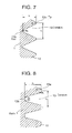
- the relations between the height h and pitch p of the tooth, and the thickness ⁇ of the boundary layer 21 on the chord surface of the blade given by Eq.(1) are determined as follows:
- the tip 13a of the triangular tooth of the third embodiment of FIG. 7 and the corner 13a of the trapezoid tooth of the fourth embodiment of FIG.8 are rounded by radius R1.
- the root or the corners of the root 13b of the tooth are rounded by radius R2.
- the corner and fillet radii R1 and R2 preferably do not exceed 10% of the tooth height h.
- blade surface boundary layer 21 is formed between air stream S and the surface of the blade 1, i.e. the upper chord surface 1a and lower chord surface 1b, as shown in FIG.11.
- Flow loss due to the blade surface boundary layer 21 decreases as the thickness ⁇ of the blade surface boundary layer 21 decreases resulting in increased performance of the blade 1.
- the thickness ⁇ of the boundary layer 21 increases in proportion to the chord length L of the blade as recognized by Eq.(1).
- the flow loss in the vicinity of the dentation 13 is decreased and the performance of the blade is increased by increasing the ratio (h/ ⁇ ) of the tooth height h of the dentation to the thickness ⁇ of the boundary layer 21 on the upper chord surface 1a and lower chord surface 1b, that is, by increasing the tooth height h of the dentation or by decreasing the thickness ⁇ of the boundary layer 21.
- the thickness ⁇ of the boundary layer 21 decreases when the chord length L is decreased, but the strength of the blade decreases and the output (lift F) of the blade 1 also decreases with decrease chord length.
- the blade 1 is configured so that the ratio(h/ ⁇ ) of the tooth height h of the dentation to the thickness ⁇ of the boundary layer 21 on the upper chord surface 1a and lower chord face 1b is 1.0 ⁇ 10.0.
- non-periodic vortexes 17 rotating about the longitudinal lines parallel to the direction of wind and passing the tips 13a and roots 13b of the dentation 13(longitudinal vortex tubes) are generated as shown in FIG.1 under the operation of said wind turbine provided with a nacelle.
- the vortexes 17 interfere with the generation of Karman vortex street and the noise due to the Karman vortex street is suppressed.
- the tooth height h when the ratio (h/p) of the height h to pitch p of the tooth of the dentation 13 is smaller than 0.5, the tooth height h must be small, the trailing edge of the trailing edge part 12 approximates a flat trailing edge, and the generation of said vortex tube 17 generated owing to the dentation and the consequent effect of suppressing the generation of Karman vortex street can not be expected.
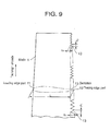
- the tooth height h is varied along the length of the blade so that the ratio (h/ ⁇ ) of the tooth height h of the dentation 13 to the thickness ⁇ of the boundary layer 21 on the upper and lower chord surface 1a, 1b is constant along the length of the blade.
- reference numeral 11 is the leading edge part
- 12 is the trailing edge part of the blade 1.
- Letter L indicates the chord length which is reduced toward the outer end of the blade 1.
- the flow loss owing to the blade surface boundary layer 21 can be suppressed to a constant value along the length of the blade 1.
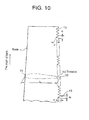
- the tooth height h and pitch p of the dentation 13 are constant along the length of the blade, and the chord length L of the blade 1 is decreased toward the outer end of the blade 1 along the lengththereof so that the ratio (h/ ⁇ ) of the tooth height h of the dentation 13 to the thickness ⁇ of the boundary layer 21 on the upper and lower chord surface 1a, 1b increases toward the outer end of the blade 1 along the length thereof .
- reference numeral 11 is the leading edge part
- 12 is the trailing edge part of the blade 1.
- the tooth height h of the dentation 13 is constant along the length of the blade and the chord length L of the blade is decreased toward the outer end of the blade along the length thereof so that the ratio(h/ ⁇ ) of the tooth height h to the thickness ⁇ of the blade surface boundary layer 21 increases toward the outer end of the blade along the length thereof, so the flow loss due to the blade surface boundary layer is decreased toward the outer end of the blade, where the rotating force obtained from wind force is larger for increased radius from the center of rotation axis of blade.
- the blade can achieve high efficiency over the length of the blade 1 with the chord length L of the blade determined to the minimum value for securing the strength of the blade 1.
- a one-piece blade or the main blade body of a split-type blade is made of light weight, high-strength metal, preferably aluminum alloy including high strength aluminum, the blade can be formed into a thin blade while maintaining the strength thereof.
- the performance of blade can be largely increased by forming the blade to be thinner and smaller.
- the thickness of the trailing edge of blade can be decreased to a minimum value (about 2mm) by making the main blade body of high-strength metal, and in addition, through forming dentation in the trailing edge part along the length of the blade, the generation of Karman vortex street downstream from the trailing edge is completely prevented. As a result, the noise due to the generation of Karman vortex street can be positively suppressed.
- a thin blade of high strength which is light in weight and has the strength strong enough for a sporadic heavy load acting on the blade in case a gust of wind or earthquake occurs, and the blade having high durability and reliability despite its decreased thickness can be provided, with which the damage of blade when heavy load acts on the blade is evaded.
- the combination of materials of the main blade body and rear end part can be arbitrarily determined. Therefore, by forming the main blade body out of light metal such as aluminum alloy and titanium alloy, and forming the rear end part, which constitutes a relatively small percentage of the weight of the blade, out of high-strength steel or titanium alloy which is easy to be formed into thin trailing edge part and also easy to be formed to have dentation 13, the wind turbine blade can be provided with its performance largely improved and the noise due to the generation of Karman vortex street positively suppressed.
- the flow loss in the vicinity of the dentation is decreased and the blade performance is increased by increasing the ratio (h/ ⁇ ) of the tooth height h of the dentation to the thickness ⁇ of the boundary layer.
- the tooth height h is decreased toward the outer end of the blade along the length thereof so that the ratio (h/ ⁇ ) of the tooth height h of the dentation to the thickness ⁇ of the boundary layer is constant along the length of the blade, the flow loss owing to the blade surface boundary layer can be suppressed to a constant value along the length of the blade, and the tooth height h is decreased in proportion to the chord length L along the length of the blade resulting in a balanced blade strength and output(lift) along the length of the blade.
- the tooth height h of the dentation is constant along the length of the blade and the chord length L of the blade is decreased toward the outer end of the blade along the length thereof so that the ratio (h/ ⁇ ) of the tooth height h to the thickness ⁇ of the blade surface boundary layer increases toward the outer end of the blade along the length thereof, so the flow loss due to the blade surface boundary layer is decreased toward the outer end of the blade, where the rotating force obtained from wind force is larger for increased radius, and the blade can achieve high efficiency over the length of the blade with the chord length L of the blade determined to the minimum value for securing the strength of the blade.
- non-periodic vortexes rotating about the longitudinal lines parallel to the direction of wind and passing the tips and roots of the teeth are generated under the operation of the wind turbine .
- the vortexes interfere with the generation of Karman vortex street, and the noise due to the Karman vortex street is suppressed.
- a wind turbine blade can be provided, which has the strength strong enough for sporadic heavy load, has high durability and reliability, is capable of being formed into a thin blade.
- wind turbine performance can be increased, the noise due to the generation of Karman vortex street can be suppressed, and further blade structure is simplified resulting in the reduction of blade production man-hour.
Landscapes
- Engineering & Computer Science (AREA)
- Life Sciences & Earth Sciences (AREA)
- Sustainable Development (AREA)
- Sustainable Energy (AREA)
- Chemical & Material Sciences (AREA)
- Combustion & Propulsion (AREA)
- Mechanical Engineering (AREA)
- General Engineering & Computer Science (AREA)
- Physics & Mathematics (AREA)
- Fluid Mechanics (AREA)
- Wind Motors (AREA)
Applications Claiming Priority (4)
| Application Number | Priority Date | Filing Date | Title |
|---|---|---|---|
| JP2002046192 | 2002-02-22 | ||
| JP2002046192 | 2002-02-22 | ||
| JP2002069737 | 2002-03-14 | ||
| JP2002069737 | 2002-03-14 |
Publications (2)
| Publication Number | Publication Date |
|---|---|
| EP1338793A2 true EP1338793A2 (fr) | 2003-08-27 |
| EP1338793A3 EP1338793A3 (fr) | 2010-09-01 |
Family
ID=27667554
Family Applications (1)
| Application Number | Title | Priority Date | Filing Date |
|---|---|---|---|
| EP03003852A Withdrawn EP1338793A3 (fr) | 2002-02-22 | 2003-02-20 | Bord de fuite cranelée pour pale d'éolienne |
Country Status (4)
| Country | Link |
|---|---|
| US (1) | US6830436B2 (fr) |
| EP (1) | EP1338793A3 (fr) |
| CN (1) | CN100347443C (fr) |
| BR (1) | BR0300233B8 (fr) |
Cited By (32)
| Publication number | Priority date | Publication date | Assignee | Title |
|---|---|---|---|---|
| EP1963669A1 (fr) * | 2005-12-20 | 2008-09-03 | Lm Glasfiber A/S | Lame de rotor de turbine a vent comprenant une section de bord trainant de section transversale constante |
| EP2028366A2 (fr) | 2007-05-31 | 2009-02-25 | Gamesa Innovation & Technology, S.L. | Pale d'éolienne avec dispositifs d'insonorisation |
| DE102008037368A1 (de) | 2007-09-19 | 2009-04-02 | General Electric Co. | Rotorflügel mit Hinterkantenzackenprofilen |
| GB2466478A (en) * | 2008-12-02 | 2010-06-30 | Aerovortex Mills Ltd | Suction generation device |
| US7874788B2 (en) | 2004-09-17 | 2011-01-25 | Clean Current Limited Partnership | Flow enhancement for underwater turbine |
| WO2012042245A1 (fr) | 2010-09-30 | 2012-04-05 | Imperial Innovations Ltd | Appareil de modification d'écoulement de fluide et procédé de fabrication |
| EP2363600A3 (fr) * | 2010-03-03 | 2012-04-25 | Richard Caires | Système d'éolienne avec une incidence sonore et visuelle réduite |
| CN102454540A (zh) * | 2010-11-04 | 2012-05-16 | 通用电气公司 | 用于风力涡轮机转子叶片的降噪装置 |
| EP2646682A1 (fr) * | 2010-11-30 | 2013-10-09 | General Electric Company | Réducteur de bruit pour pale de rotor dans une turbine éolienne |
| US8657561B2 (en) | 2009-09-24 | 2014-02-25 | Rolls-Royce Plc | Variable shape rotor blade |
| DK177756B1 (da) * | 2007-02-07 | 2014-06-02 | Gen Electric | Rotorvingebagkantenhed og fremgangsmåde til anvendelse |
| WO2014086564A1 (fr) * | 2012-12-07 | 2014-06-12 | Wobben Properties Gmbh | Éolienne |
| EP2811156A1 (fr) * | 2013-06-07 | 2014-12-10 | Siemens Aktiengesellschaft | Pale de rotor d'éolienne |
| DK177953B1 (en) * | 2011-11-21 | 2015-02-02 | Gen Electric | Blade extension for rotor blade in wind turbine |
| US9000604B2 (en) | 2010-04-30 | 2015-04-07 | Clean Current Limited Partnership | Unidirectional hydro turbine with enhanced duct, blades and generator |
| FR3013324A1 (fr) * | 2013-11-19 | 2015-05-22 | Airbus Sas | Antenne d'aeronef |
| DK178175B1 (en) * | 2010-06-24 | 2015-07-20 | Gen Electric | Fastening Device for Rotor Blade Component |
| DK178192B1 (en) * | 2010-12-16 | 2015-08-03 | Gen Electric | Noise reduction device for rotor blades in a wind turbine |
| WO2016008874A1 (fr) | 2014-07-14 | 2016-01-21 | Lm Wp Patent Holding A/S | Pièce d'extension de coque aérodynamique pour une pale de turbine éolienne |
| EP3009669A1 (fr) * | 2014-10-17 | 2016-04-20 | Mitsubishi Heavy Industries, Ltd. | Panneau latéral de bord de fuite |
| US9719488B2 (en) | 2013-09-18 | 2017-08-01 | Siemens Aktiengesellschaft | Arrangement to reduce noise of a wind turbine rotor blade |
| WO2017148669A1 (fr) * | 2016-02-29 | 2017-09-08 | Senvion Gmbh | Dentelures à rainures de décharge |
| US9841002B2 (en) | 2013-09-18 | 2017-12-12 | Siemens Aktiengesellschaft | Wind turbine rotor blade with serrated extension |
| US9849976B2 (en) | 2014-08-19 | 2017-12-26 | The Boeing Company | Noise reducing profile for helicopter rotor blade tracking wedges |
| CN108119916A (zh) * | 2016-11-30 | 2018-06-05 | 安萨尔多能源瑞士股份公司 | 涡流生成装置 |
| US10502187B2 (en) | 2016-05-27 | 2019-12-10 | Siemens Gamesa Renewable Energy A/S | Rotor blade with noise reduction means |
| US10900465B2 (en) | 2014-06-16 | 2021-01-26 | Brunel University London | Noise reduction to the trailing edge of fluid dynamic bodies |
| US11181093B2 (en) | 2014-06-18 | 2021-11-23 | Siemens Gamesa Renewable Energy A/S | Rotor blade with noise reduction means |
| US11236722B2 (en) | 2018-06-27 | 2022-02-01 | Siemens Gamesa Renewable Energy A/S | Aerodynamic structure |
| US11359600B2 (en) | 2018-06-27 | 2022-06-14 | Siemens Gamesa Renewable Energy A/S | Aerodynamic structure |
| WO2024010549A1 (fr) * | 2022-07-05 | 2024-01-11 | Koese Cevdet | Aile de glissement et d'équilibrage |
| WO2024108302A1 (fr) * | 2022-11-23 | 2024-05-30 | Biomerenewables Inc. | Structure à dentelures adaptées pour traverser un environnement fluide |
Families Citing this family (76)
| Publication number | Priority date | Publication date | Assignee | Title |
|---|---|---|---|---|
| JP4432865B2 (ja) * | 2004-09-30 | 2010-03-17 | ダイキン工業株式会社 | 送風機の羽根車およびそれを用いた空気調和機 |
| US7637721B2 (en) * | 2005-07-29 | 2009-12-29 | General Electric Company | Methods and apparatus for producing wind energy with reduced wind turbine noise |
| ES2318925B1 (es) * | 2005-09-22 | 2010-02-11 | GAMESA INNOVATION & TECHNOLOGY, S.L. | Aerogenerador con un rotor de palas que reduce el ruido. |
| US7458777B2 (en) * | 2005-09-22 | 2008-12-02 | General Electric Company | Wind turbine rotor assembly and blade having acoustic flap |
| EP1801422B1 (fr) * | 2005-12-22 | 2013-06-12 | Ziehl-Abegg AG | Ventilateur et aube de ventilateur |
| JP4973249B2 (ja) * | 2006-03-31 | 2012-07-11 | ダイキン工業株式会社 | 多翼ファン |
| CN100412356C (zh) * | 2006-08-31 | 2008-08-20 | 东莞中德风电能源有限公司 | 风能发电机的叶片的制造方法 |
| ES2310958B1 (es) * | 2006-09-15 | 2009-11-10 | GAMESA INNOVATION & TECHNOLOGY, S.L. | Pala de aerogenerador optimizada. |
| US7766620B2 (en) * | 2007-02-08 | 2010-08-03 | General Electricc Company | Rotor blade with a lightning protection unit, wind energy system having the same and a method for constructing a rotor blade |
| JP3996945B1 (ja) * | 2007-02-20 | 2007-10-24 | 常夫 野口 | 垂直軸型風車 |
| DE102008006437A1 (de) * | 2008-01-28 | 2009-08-13 | Eurocopter Deutschland Gmbh | Aerodynamisches Hochleistungsprofil für Luftfahrzeuge |
| WO2010048152A1 (fr) * | 2008-10-20 | 2010-04-29 | Drexel University | Eolienne à axe vertical |
| CA2763898A1 (fr) * | 2009-06-03 | 2010-12-09 | Flodesign Wind Turbine Corp. | Pales d'eoliennes a lobes de melange |
| US20110006165A1 (en) * | 2009-07-10 | 2011-01-13 | Peter Ireland | Application of conformal sub boundary layer vortex generators to a foil or aero/ hydrodynamic surface |
| CN101994642B (zh) * | 2009-08-21 | 2012-07-04 | 浙江恒通机械有限公司 | 不同铸造铝合金制成的风电机叶片 |
| WO2011157849A2 (fr) * | 2010-06-18 | 2011-12-22 | Suzlon Blade Technology B.V. | Pale de rotor pour éolienne |
| US8083488B2 (en) | 2010-08-23 | 2011-12-27 | General Electric Company | Blade extension for rotor blade in wind turbine |
| DE102010040911A1 (de) | 2010-09-16 | 2012-03-22 | Aloys Wobben | Magnus-Rotor |
| DE102010040917A1 (de) * | 2010-09-16 | 2012-03-22 | Aloys Wobben | Magnus-Rotor |
| US7976283B2 (en) * | 2010-11-10 | 2011-07-12 | General Electric Company | Noise reducer for rotor blade in wind turbine |
| US8523515B2 (en) | 2010-11-15 | 2013-09-03 | General Electric Company | Noise reducer for rotor blade in wind turbine |
| US8556584B2 (en) * | 2011-02-03 | 2013-10-15 | General Electric Company | Rotating component of a turbine engine |
| US10030872B2 (en) * | 2011-02-28 | 2018-07-24 | General Electric Company | Combustor mixing joint with flow disruption surface |
| US20130291548A1 (en) * | 2011-02-28 | 2013-11-07 | General Electric Company | Combustor mixing joint and methods of improving durability of a first stage bucket of a turbine |
| EP2514962B1 (fr) * | 2011-04-19 | 2017-08-02 | Siemens Aktiengesellschaft | Déflecteur pour pale d'éolienne |
| US9581133B2 (en) * | 2011-05-16 | 2017-02-28 | Lm Windpower A/S | Wind turbine blade with noise reduction devices and related method |
| US8414261B2 (en) * | 2011-05-31 | 2013-04-09 | General Electric Company | Noise reducer for rotor blade in wind turbine |
| US8834127B2 (en) | 2011-09-09 | 2014-09-16 | General Electric Company | Extension for rotor blade in wind turbine |
| US8834117B2 (en) | 2011-09-09 | 2014-09-16 | General Electric Company | Integrated lightning receptor system and trailing edge noise reducer for a wind turbine rotor blade |
| KR20130064087A (ko) | 2011-10-12 | 2013-06-17 | 미츠비시 쥬고교 가부시키가이샤 | 풍차 날개, 이것을 구비한 풍력 발전 장치 및 풍차 날개의 설계 방법 |
| KR101826359B1 (ko) * | 2011-11-22 | 2018-02-06 | 엘지전자 주식회사 | 횡류팬 및 공기 조화기 |
| DE102012209935A1 (de) * | 2011-12-08 | 2013-06-13 | Wobben Properties Gmbh | Hinterkasten, Rotorblatt mit Hinterkasten und Windenergieanlage mit solchem Rotorblatt |
| US9341158B2 (en) | 2011-12-08 | 2016-05-17 | Inventus Holdings, Llc | Quiet wind turbine blade |
| US8430638B2 (en) | 2011-12-19 | 2013-04-30 | General Electric Company | Noise reducer for rotor blade in wind turbine |
| US20130164141A1 (en) * | 2011-12-22 | 2013-06-27 | General Electric Company | Blade with semi-rigid trailing edge |
| CN102588339B (zh) * | 2012-03-01 | 2016-02-03 | Tcl空调器(中山)有限公司 | 风扇结构及轴流风扇 |
| CA147876S (en) | 2012-04-11 | 2013-09-27 | Wobben Properties Gmbh | Wind turbine rotor blade |
| ES2679128T3 (es) * | 2012-12-07 | 2018-08-22 | Wobben Properties Gmbh | Borde de fuga de pala de rotor |
| USD750560S1 (en) | 2013-04-11 | 2016-03-01 | Wobben Properties Gmbh | Wind turbine blade |
| EP2851554A1 (fr) * | 2013-09-18 | 2015-03-25 | Siemens Aktiengesellschaft | Agencement permettant de réduire l'émission de bruit |
| US9981756B2 (en) | 2013-10-15 | 2018-05-29 | Rosemount Aerospace Inc. | Total air temperature sensors |
| CN104833443B (zh) * | 2013-10-15 | 2018-10-02 | 罗斯蒙特航天公司 | 总空气温度传感器 |
| US9494134B2 (en) | 2013-11-20 | 2016-11-15 | General Electric Company | Noise reducing extension plate for rotor blade in wind turbine |
| BR112016030174B1 (pt) * | 2014-07-03 | 2022-07-19 | Lm Wp Patent Holding A/S | Pá de turbina eólica |
| DE102014213929A1 (de) | 2014-07-17 | 2016-01-21 | Wobben Properties Gmbh | Rotorblatthinterkante |
| DE102014213930A1 (de) | 2014-07-17 | 2016-01-21 | Wobben Properties Gmbh | Rotorblattspitzenhinterkante |
| DE102014214220A1 (de) * | 2014-07-22 | 2016-01-28 | Wobben Properties Gmbh | Hinterkantensegment eines Rotorblatts |
| US11035340B2 (en) | 2014-08-05 | 2021-06-15 | Biomerenewables Inc. | Fluidic turbine structure |
| CN106574603B (zh) | 2014-08-05 | 2019-12-24 | 瑞安·丘奇 | 具有适于横穿流体环境的刚性小翼的结构 |
| BR112017002317B1 (pt) | 2014-08-05 | 2022-11-22 | Ryan Church | Estrutura de redirecionamento de fluido |
| DK3177524T3 (en) * | 2014-08-05 | 2021-02-15 | Biomerenewables Inc | Wind turbine rotor blade |
| US10180125B2 (en) | 2015-04-20 | 2019-01-15 | General Electric Company | Airflow configuration for a wind turbine rotor blade |
| US10240576B2 (en) * | 2015-11-25 | 2019-03-26 | General Electric Company | Wind turbine noise reduction with acoustically absorbent serrations |
| EP3181895A1 (fr) * | 2015-12-17 | 2017-06-21 | LM WP Patent Holding A/S | Système à plaque de séparation pour une pale de turbine éolienne dentelée |
| US10539025B2 (en) | 2016-02-10 | 2020-01-21 | General Electric Company | Airfoil assembly with leading edge element |
| EP3205874B2 (fr) * | 2016-02-12 | 2023-11-01 | LM Wind Power A/S | Panneau de bord de fuite dentelé pour une pale d'éolienne |
| CN105804955B (zh) * | 2016-03-11 | 2020-11-27 | 北京金风科创风电设备有限公司 | 风力发电机组用叶片及风力发电机组 |
| US11002246B2 (en) * | 2016-04-15 | 2021-05-11 | Siemens Gamesa Renewable Energy A/S | Rotor blade with a serrated trailing edge |
| USD850376S1 (en) * | 2016-06-24 | 2019-06-04 | William Scott Keeley | Fluid turbine rotor blade |
| USD850377S1 (en) * | 2016-06-24 | 2019-06-04 | William Scott Keeley | Fluid turbine mixing rotor blade |
| US10465652B2 (en) | 2017-01-26 | 2019-11-05 | General Electric Company | Vortex generators for wind turbine rotor blades having noise-reducing features |
| US20190024631A1 (en) * | 2017-07-20 | 2019-01-24 | General Electric Company | Airflow configuration for a wind turbine rotor blade |
| CN107627619A (zh) * | 2017-10-17 | 2018-01-26 | 远景能源(江苏)有限公司 | 复合材料产品表面的附件安装结构及方法 |
| GB201718069D0 (en) * | 2017-11-01 | 2017-12-13 | Rolls Royce Plc | Aerofoil |
| CN109945255A (zh) * | 2017-12-20 | 2019-06-28 | 美的集团股份有限公司 | 风道结构、风机和抽油烟机 |
| US10767623B2 (en) | 2018-04-13 | 2020-09-08 | General Electric Company | Serrated noise reducer for a wind turbine rotor blade |
| CN108953053B (zh) * | 2018-07-16 | 2021-01-12 | 上海电气风电集团股份有限公司 | 一种装有梳状锯齿结构的风电叶片及其安装方法 |
| CN109083806B (zh) * | 2018-08-02 | 2020-03-13 | 辽宁工程技术大学 | 一种波浪翼型叶片及风力机 |
| US10746157B2 (en) | 2018-08-31 | 2020-08-18 | General Electric Company | Noise reducer for a wind turbine rotor blade having a cambered serration |
| GB201911619D0 (en) * | 2019-08-14 | 2019-09-25 | Lm Wind Power As | Wind turbine blade assembly and method for producing a wind turbine blade |
| JP7277316B2 (ja) * | 2019-08-30 | 2023-05-18 | 三菱重工業株式会社 | 風車翼装置及び風車翼アタッチメント部材 |
| CN110789561B (zh) * | 2019-10-14 | 2024-04-26 | 同济大学 | 一种后端设置锯齿形扰流板的排障器及其应用 |
| GB202020360D0 (en) * | 2020-12-22 | 2021-02-03 | Ge Wind Energy Gmbh | Wind turbine serrations with upstream extension |
| CN114876869B (zh) * | 2021-02-05 | 2024-08-06 | 中国航发商用航空发动机有限责任公司 | 风扇叶片以及航空发动机 |
| CN113859296B (zh) * | 2021-10-26 | 2024-03-26 | 同济大学 | 一种带有被动扰流结构的排障器及其应用 |
| EP4306795A1 (fr) * | 2022-07-11 | 2024-01-17 | Wobben Properties GmbH | Procédé d'optimisation d'une pale de rotor d'éolienne |
Citations (1)
| Publication number | Priority date | Publication date | Assignee | Title |
|---|---|---|---|---|
| EP1112928A2 (fr) * | 1999-12-31 | 2001-07-04 | DLR Deutsches Zentrum für Luft- und Raumfahrt e.V. | Profil aérodynamique avec bord de fuite améliorant la performance |
Family Cites Families (15)
| Publication number | Priority date | Publication date | Assignee | Title |
|---|---|---|---|---|
| US4540333A (en) * | 1981-06-12 | 1985-09-10 | Weisbrich Alfred L | TARP Rotor system thrust, yaw and load control |
| DE3435458A1 (de) * | 1984-09-27 | 1986-06-12 | Erich Herter | Windturbine |
| US5088665A (en) * | 1989-10-31 | 1992-02-18 | The United States Of America As Represented By The Administrator Of The National Aeronautics And Space Administration | Serrated trailing edges for improving lift and drag characteristics of lifting surfaces |
| DE4225599A1 (de) * | 1992-08-03 | 1994-02-17 | Harald Dr Kayser | Tragflügel für Windenergieanlage |
| JPH0777211A (ja) | 1993-06-28 | 1995-03-20 | Mitsubishi Heavy Ind Ltd | 板状物体後流の制御装置 |
| US5375324A (en) * | 1993-07-12 | 1994-12-27 | Flowind Corporation | Vertical axis wind turbine with pultruded blades |
| NL9301910A (nl) * | 1993-11-04 | 1995-06-01 | Stork Prod Eng | Windturbine. |
| JPH07332007A (ja) | 1994-06-13 | 1995-12-19 | Hitachi Ltd | タービン静翼 |
| DE19546008A1 (de) * | 1995-12-09 | 1997-06-12 | Abb Patent Gmbh | Turbinenschaufel, die für den Einsatz im Naßdampfbereich von Vorend- und Endstufen von Turbinen vorgesehen ist |
| US5873699A (en) * | 1996-06-27 | 1999-02-23 | United Technologies Corporation | Discontinuously reinforced aluminum gas turbine guide vane |
| DE19644264A1 (de) * | 1996-10-24 | 1998-05-07 | Manfred Grefe | Rotorblatt für Windkraftanlagen und Herstellungsverfahren dafür |
| JPH11201021A (ja) | 1998-01-06 | 1999-07-27 | Mitsubishi Heavy Ind Ltd | 風車翼 |
| JP2000120524A (ja) * | 1998-10-16 | 2000-04-25 | Mitsubishi Heavy Ind Ltd | 風車翼 |
| DE19950620C1 (de) * | 1999-10-20 | 2001-04-12 | Aloys Wobben | Rotorblatt |
| US6733240B2 (en) * | 2001-07-18 | 2004-05-11 | General Electric Company | Serrated fan blade |
-
2003
- 2003-02-20 EP EP03003852A patent/EP1338793A3/fr not_active Withdrawn
- 2003-02-21 BR BRPI0300233-0A patent/BR0300233B8/pt not_active IP Right Cessation
- 2003-02-21 CN CNB031105513A patent/CN100347443C/zh not_active Expired - Fee Related
- 2003-02-21 US US10/370,073 patent/US6830436B2/en not_active Expired - Fee Related
Patent Citations (1)
| Publication number | Priority date | Publication date | Assignee | Title |
|---|---|---|---|---|
| EP1112928A2 (fr) * | 1999-12-31 | 2001-07-04 | DLR Deutsches Zentrum für Luft- und Raumfahrt e.V. | Profil aérodynamique avec bord de fuite améliorant la performance |
Cited By (49)
| Publication number | Priority date | Publication date | Assignee | Title |
|---|---|---|---|---|
| US7874788B2 (en) | 2004-09-17 | 2011-01-25 | Clean Current Limited Partnership | Flow enhancement for underwater turbine |
| EP1963669A1 (fr) * | 2005-12-20 | 2008-09-03 | Lm Glasfiber A/S | Lame de rotor de turbine a vent comprenant une section de bord trainant de section transversale constante |
| DK177756B1 (da) * | 2007-02-07 | 2014-06-02 | Gen Electric | Rotorvingebagkantenhed og fremgangsmåde til anvendelse |
| EP2028366A2 (fr) | 2007-05-31 | 2009-02-25 | Gamesa Innovation & Technology, S.L. | Pale d'éolienne avec dispositifs d'insonorisation |
| DE102008037368A1 (de) | 2007-09-19 | 2009-04-02 | General Electric Co. | Rotorflügel mit Hinterkantenzackenprofilen |
| GB2466478A (en) * | 2008-12-02 | 2010-06-30 | Aerovortex Mills Ltd | Suction generation device |
| US8657561B2 (en) | 2009-09-24 | 2014-02-25 | Rolls-Royce Plc | Variable shape rotor blade |
| EP2363600A3 (fr) * | 2010-03-03 | 2012-04-25 | Richard Caires | Système d'éolienne avec une incidence sonore et visuelle réduite |
| US9000604B2 (en) | 2010-04-30 | 2015-04-07 | Clean Current Limited Partnership | Unidirectional hydro turbine with enhanced duct, blades and generator |
| DK178175B1 (en) * | 2010-06-24 | 2015-07-20 | Gen Electric | Fastening Device for Rotor Blade Component |
| GB2493293A (en) * | 2010-09-30 | 2013-01-30 | Imp Innovations Ltd | Fluid flow modification apparatus with multi-scale trailing edge |
| CN103124854A (zh) * | 2010-09-30 | 2013-05-29 | 帝国创新有限公司 | 流体流动修正装置及制造方法 |
| GB2493293B (en) * | 2010-09-30 | 2013-08-07 | Imp Innovations Ltd | Fluid flow modification apparatus and method of manufacture |
| WO2012042245A1 (fr) | 2010-09-30 | 2012-04-05 | Imperial Innovations Ltd | Appareil de modification d'écoulement de fluide et procédé de fabrication |
| CN103124854B (zh) * | 2010-09-30 | 2015-09-30 | 帝国创新有限公司 | 流体流动修正装置及制造方法 |
| CN102454540A (zh) * | 2010-11-04 | 2012-05-16 | 通用电气公司 | 用于风力涡轮机转子叶片的降噪装置 |
| EP2646682A1 (fr) * | 2010-11-30 | 2013-10-09 | General Electric Company | Réducteur de bruit pour pale de rotor dans une turbine éolienne |
| EP2646682A4 (fr) * | 2010-11-30 | 2014-08-06 | Gen Electric | Réducteur de bruit pour pale de rotor dans une turbine éolienne |
| DK178192B1 (en) * | 2010-12-16 | 2015-08-03 | Gen Electric | Noise reduction device for rotor blades in a wind turbine |
| DK177953B1 (en) * | 2011-11-21 | 2015-02-02 | Gen Electric | Blade extension for rotor blade in wind turbine |
| KR101804029B1 (ko) | 2012-12-07 | 2017-12-01 | 보벤 프로퍼티즈 게엠베하 | 풍력 발전 설비 |
| WO2014086564A1 (fr) * | 2012-12-07 | 2014-06-12 | Wobben Properties Gmbh | Éolienne |
| AU2013354400B2 (en) * | 2012-12-07 | 2016-10-13 | Wobben Properties Gmbh | Wind power plant |
| RU2610971C2 (ru) * | 2012-12-07 | 2017-02-17 | Воббен Пропертиз Гмбх | Ветровая энергетическая установка |
| US10082129B2 (en) | 2012-12-07 | 2018-09-25 | Wobben Properties Gmbh | Wind turbine |
| EP2811156A1 (fr) * | 2013-06-07 | 2014-12-10 | Siemens Aktiengesellschaft | Pale de rotor d'éolienne |
| US9719488B2 (en) | 2013-09-18 | 2017-08-01 | Siemens Aktiengesellschaft | Arrangement to reduce noise of a wind turbine rotor blade |
| US9841002B2 (en) | 2013-09-18 | 2017-12-12 | Siemens Aktiengesellschaft | Wind turbine rotor blade with serrated extension |
| FR3013324A1 (fr) * | 2013-11-19 | 2015-05-22 | Airbus Sas | Antenne d'aeronef |
| US10900465B2 (en) | 2014-06-16 | 2021-01-26 | Brunel University London | Noise reduction to the trailing edge of fluid dynamic bodies |
| US11181093B2 (en) | 2014-06-18 | 2021-11-23 | Siemens Gamesa Renewable Energy A/S | Rotor blade with noise reduction means |
| EP3169895B1 (fr) | 2014-07-14 | 2019-09-11 | LM WP Patent Holding A/S | Coque d'extension pour pale d'éolienne |
| US11143160B2 (en) | 2014-07-14 | 2021-10-12 | Lm Wp Patent Holding A/S | Aeroshell extender piece for a wind turbine blade |
| WO2016008874A1 (fr) | 2014-07-14 | 2016-01-21 | Lm Wp Patent Holding A/S | Pièce d'extension de coque aérodynamique pour une pale de turbine éolienne |
| CN106471246A (zh) * | 2014-07-14 | 2017-03-01 | Lm Wp 专利控股有限公司 | 用于空气动力学壳体扩展件的附接的型材楔形件 |
| US10458389B2 (en) | 2014-07-14 | 2019-10-29 | Lm Wp Patent Holding A/S | Profile wedge for attachment of an aeroshell extender piece |
| CN106471246B (zh) * | 2014-07-14 | 2020-06-30 | Lm Wp 专利控股有限公司 | 用于空气动力学壳体扩展件的附接的型材楔形件 |
| US9849976B2 (en) | 2014-08-19 | 2017-12-26 | The Boeing Company | Noise reducing profile for helicopter rotor blade tracking wedges |
| JP2016079905A (ja) * | 2014-10-17 | 2016-05-16 | 三菱重工業株式会社 | 後縁側パネル |
| EP3009669A1 (fr) * | 2014-10-17 | 2016-04-20 | Mitsubishi Heavy Industries, Ltd. | Panneau latéral de bord de fuite |
| WO2017148669A1 (fr) * | 2016-02-29 | 2017-09-08 | Senvion Gmbh | Dentelures à rainures de décharge |
| US10502187B2 (en) | 2016-05-27 | 2019-12-10 | Siemens Gamesa Renewable Energy A/S | Rotor blade with noise reduction means |
| US10865986B2 (en) | 2016-11-30 | 2020-12-15 | Ansaldo Energia Switzerland AG | Vortex generating device |
| CN108119916A (zh) * | 2016-11-30 | 2018-06-05 | 安萨尔多能源瑞士股份公司 | 涡流生成装置 |
| CN108119916B (zh) * | 2016-11-30 | 2021-12-14 | 安萨尔多能源瑞士股份公司 | 涡流生成装置 |
| US11236722B2 (en) | 2018-06-27 | 2022-02-01 | Siemens Gamesa Renewable Energy A/S | Aerodynamic structure |
| US11359600B2 (en) | 2018-06-27 | 2022-06-14 | Siemens Gamesa Renewable Energy A/S | Aerodynamic structure |
| WO2024010549A1 (fr) * | 2022-07-05 | 2024-01-11 | Koese Cevdet | Aile de glissement et d'équilibrage |
| WO2024108302A1 (fr) * | 2022-11-23 | 2024-05-30 | Biomerenewables Inc. | Structure à dentelures adaptées pour traverser un environnement fluide |
Also Published As
| Publication number | Publication date |
|---|---|
| BR0300233B1 (pt) | 2013-01-08 |
| US20030175121A1 (en) | 2003-09-18 |
| BR0300233A (pt) | 2004-08-03 |
| CN100347443C (zh) | 2007-11-07 |
| BR0300233B8 (pt) | 2013-02-19 |
| CN1442609A (zh) | 2003-09-17 |
| EP1338793A3 (fr) | 2010-09-01 |
| US6830436B2 (en) | 2004-12-14 |
Similar Documents
| Publication | Publication Date | Title |
|---|---|---|
| US6830436B2 (en) | Wind turbine provided with nacelle | |
| US8317483B2 (en) | Wind turbine rotor blade | |
| ES2910416T3 (es) | Inserto de pala para una pala de rotor de un aerogenerador | |
| EP2834517B1 (fr) | Base de pale vrillée | |
| EP2604856B1 (fr) | Pale de turbine éolienne, dispositif générateur d'énergie éolienne équipé de cette pale et procédé de calcul pour une pale de turbine éolienne | |
| EP3085952B1 (fr) | Configuration d'écoulement d'air pour une pale de rotor de turbine éolienne | |
| EP2432994B1 (fr) | Pale d'eolienne a partie de base presentant une cambrure zero ou non positive | |
| EP2432996B1 (fr) | Procédé de fonctionnement d'une éolienne | |
| EP2432995B1 (fr) | Pale d'éolienne avec partie de base présentant une torsion inhérente non idéale | |
| US9523279B2 (en) | Rotor blade fence for a wind turbine | |
| EP2309119A1 (fr) | Pale d'eolienne et generateur eolien l'utilisant | |
| EP3844386B1 (fr) | Réducteur de bruit pour pale de rotor d'éolienne à dentelure cambrée | |
| US20110229332A1 (en) | Wind Turbine Rotor Blade | |
| JP2003336572A (ja) | ナセル構造の風車 | |
| US8105034B2 (en) | Vertical-axis wind turbine and method for the production thereof | |
| JP2015078667A (ja) | 風車翼及び風力発電装置 | |
| CN116157597A (zh) | 风力涡轮机 | |
| CN111396243B (zh) | 一种三腹板结构的大型风电机组叶片及组装方法 | |
| WO2016057120A1 (fr) | Entretoise pour pale de rotor de turbine éolienne | |
| US20240167450A1 (en) | A wind turbine blade | |
| CN109312710B (zh) | 风能设备的转子叶片 | |
| CN103939278A (zh) | 风力涡轮机叶片 | |
| CN115803520A (zh) | 风力涡轮机 | |
| EP2851557A1 (fr) | Pale d'eolienne avec des volets aérodynamiques placés au pied de la pale |
Legal Events
| Date | Code | Title | Description |
|---|---|---|---|
| PUAI | Public reference made under article 153(3) epc to a published international application that has entered the european phase |
Free format text: ORIGINAL CODE: 0009012 |
|
| 17P | Request for examination filed |
Effective date: 20030220 |
|
| AK | Designated contracting states |
Designated state(s): AT BE BG CH CY CZ DE DK EE ES FI FR GB GR HU IE IT LI LU MC NL PT SE SI SK TR |
|
| AX | Request for extension of the european patent |
Extension state: AL LT LV MK RO |
|
| PUAL | Search report despatched |
Free format text: ORIGINAL CODE: 0009013 |
|
| AK | Designated contracting states |
Kind code of ref document: A3 Designated state(s): AT BE BG CH CY CZ DE DK EE ES FI FR GB GR HU IE IT LI LU MC NL PT SE SI SK TR |
|
| AX | Request for extension of the european patent |
Extension state: AL LT LV MK RO |
|
| 17Q | First examination report despatched |
Effective date: 20110311 |
|
| AKX | Designation fees paid |
Designated state(s): AT BE BG CH CY CZ DE DK EE ES FI FR GB GR HU IE IT LI LU MC NL PT SE SI SK TR |
|
| STAA | Information on the status of an ep patent application or granted ep patent |
Free format text: STATUS: THE APPLICATION IS DEEMED TO BE WITHDRAWN |
|
| 18D | Application deemed to be withdrawn |
Effective date: 20110922 |