EP1338762A2 - Ventilschaftabdichtung an Verbrennungskraftmaschinen - Google Patents
Ventilschaftabdichtung an Verbrennungskraftmaschinen Download PDFInfo
- Publication number
- EP1338762A2 EP1338762A2 EP03002943A EP03002943A EP1338762A2 EP 1338762 A2 EP1338762 A2 EP 1338762A2 EP 03002943 A EP03002943 A EP 03002943A EP 03002943 A EP03002943 A EP 03002943A EP 1338762 A2 EP1338762 A2 EP 1338762A2
- Authority
- EP
- European Patent Office
- Prior art keywords
- valve stem
- holding part
- wall parts
- wall
- guide
- Prior art date
- Legal status (The legal status is an assumption and is not a legal conclusion. Google has not performed a legal analysis and makes no representation as to the accuracy of the status listed.)
- Granted
Links
Images

Classifications
-
- F—MECHANICAL ENGINEERING; LIGHTING; HEATING; WEAPONS; BLASTING
- F01—MACHINES OR ENGINES IN GENERAL; ENGINE PLANTS IN GENERAL; STEAM ENGINES
- F01L—CYCLICALLY OPERATING VALVES FOR MACHINES OR ENGINES
- F01L3/00—Lift-valve, i.e. cut-off apparatus with closure members having at least a component of their opening and closing motion perpendicular to the closing faces; Parts or accessories thereof
- F01L3/08—Valves guides; Sealing of valve stem, e.g. sealing by lubricant
-
- F—MECHANICAL ENGINEERING; LIGHTING; HEATING; WEAPONS; BLASTING
- F01—MACHINES OR ENGINES IN GENERAL; ENGINE PLANTS IN GENERAL; STEAM ENGINES
- F01L—CYCLICALLY OPERATING VALVES FOR MACHINES OR ENGINES
- F01L2301/00—Using particular materials
Definitions
- the invention is concerned with a valve stem seal Internal combustion engines with a radial on the valve stem and on the Valve stem guide axially adjacent sealing element made of a polymer Material and a sleeve-shaped holding part holding the sealing element.
- the seal on the valve stems should prevent that Oil gets to the valve seat, but on the other hand also the valve stem is sufficient to be supplied with oil for its lubrication, so that there is no excessive wear occurs on the valve stem and on the valve stem guide. Beyond that aspired to seal the valve stem as inexpensively as possible perform while ensuring a long service life.
- valve stem seal is known from DE 199 49 248 A1 become a good seal with easy manufacture results. This valve stem seal can be used for various purposes to be used.
- Valve stem seal from a sleeve-shaped bearing a sealing lip Holding part is the axially over the sealing lip and at the same time Fastening the seal on the valve stem guide is used.
- the holding part is for this with its protruding sleeve section on the lateral surface of the Valve stem guide is pushed on and is replaced by at least one radial notched inwards from the middle area of the sleeve section Projection in an annular groove in the outer surface of the valve stem guide pressed.
- the sealing lip of the valve stem seal lies against the valve stem, while an axially protruding annular sealing lip under tension the face of the valve stem guide is pressed.
- Such Valve stem sealing requires and is high manufacturing precision complex to assemble.
- the invention is based on the object of a valve stem seal create that is easy to manufacture, the smallest possible Requires material, provides a good seal and is easy on the Valve stem guide can be installed.
- valve stem seal Type mentioned according to the invention in that the holding part as Polyhedron formed on the outer wall of the valve stem guide Has wall parts.
- Such a valve stem seal can with a Minimum of polymeric material and also metal can be produced. About that it is also easy to manufacture and assemble.
- the holding part is designed such that predetermined wall parts under spring pressure rest on the outer wall of the valve stem guide and thereby the Secure the seal on the valve stem guide.
- the holding part in cross section seen that has the shape of a triangle In many applications, it is sufficient if the holding part in cross section seen that has the shape of a triangle. Depending on the area of application, the number the wall parts lying against the outer wall of the valve stem guide increased become. A higher number of these wall parts results in a stronger fixation of the holding part on the valve stem guide.
- the wall parts of the Holding parts are preferably flat, they then lie along one Line contact on the valve stem guide. But that is also possible Widen the contact surface in which the wall parts of the holding part Bulges are provided, which on the outer diameter of the Valve stem guide are adjusted.
- the wall parts of the holding part lying between the flat wall parts have a cylindrical shape whose central axis is aligned with the axis of the Valve stem collapses. The stability of the individual parts to each other will thereby supported.
- the cylindrical wall parts of the Holding part run parallel to the valve stem axis along their entire length.
- the flat wall parts seen in cross section have a bow-like section, which supports the springing of the flat wall parts.
- the invention is therefore a valve stem seal, which thanks to the multiple flat, bendable surfaces equipped metal part can be fixed on the valve stem guide, the Metal part has n (flat) surfaces, the n contacts with the Form the outside diameter of the valve stem guide (n ⁇ 3). That, in cross section seen, polygon-like holding part overcomes by the resulting radial force the axial force and vibration caused by vibrations of the valve stem comes to avoid "pop-off” and also overwhelms any positive Pressure generated under the sealing lip.
- the characteristics of the bendable metal part allow an increased tolerance range for to compensate for the outside diameter of the valve guide, which in some Cases surface manufacturing requirements for valve guide outer diameter reduced.
- the holding part thus becomes a functional feature of the Valve stem seals.
- the dynamic range is not affected.
- the static area is limited to a static lip on the top Valve guide surface, reducing the amount of elastomer required becomes.
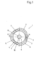
- valve stem seal 1 is in a view according to the Section line B - B shown in Figure 2.
- Figure 1 is an example of the Holding part 2 shown with three wall parts 4. The number of wall parts 4 can however, as previously described. A triangular one is visible Formation of the holding part 2 for the sealing element 3.
- the holding part 2 lies with the just formed wall parts 4 on the outer wall 5 of the valve stem guide 6 and that here there is a linear contact in points 7.
- the valve stem lies in the valve stem guide 6.
- the wall parts 4 become pressed against the outer wall 5 of the valve stem guide under spring force.
- the flat wall parts 11, 4 of the holding part 2 are through cylindrical wall parts 9 connected with each other. The central axis of these wall parts coincides with axis 10 the valve stem 8 together.
- valve stem seal 1 in section along the line A - A shown in Figure 1.
- the valve stem 8 is from the valve stem guide 6 surround.
- the holding part 2 On the valve stem guide 6, the holding part 2 is placed, which consists of flat 4 and cylindrical wall parts 9.
- the cylindrical Wall parts 9 run parallel to the valve stem axis 10.
- the flat wall parts 4 have the line contact 7 with the outer wall 5 of the valve stem guide 6. This line contact 7 extends only over part of the total length of the holding part 2.
- a bracket-like section 11 which increases the spring force of the part 4 lying directly on the wall 5.
- the sealing element 3 is with a radially enclosing the valve stem 8 Provide sealing lip 12.
- This sealing lip is usually designed in such a way that it allows a defined amount of lubricating oil to pass through adequate lubrication of the valve stem in the valve stem guide 6 given is.
- a second sealing lip 13 of the sealing element 3 is statically on the Valve stem guide 6 on its front side. For a good The sealing element 13 is used to secure the contact pressure of the radial lip 12 provided with a ring tension spring 14.
- the sealing element 3 is held by an annular flange 15 which is at the top End of the holding part 2 is arranged. To make assembly easier, that is Holding part 2 at its lower end with an outward Flanged edge 16 equipped.
Landscapes
- Engineering & Computer Science (AREA)
- Mechanical Engineering (AREA)
- General Engineering & Computer Science (AREA)
- Sealing With Elastic Sealing Lips (AREA)
- Valve-Gear Or Valve Arrangements (AREA)
Abstract
Description
- Figur 1
- eine Ansicht der Ventilschaftabdichtung gemäß der Linie B - B der Figur 2 und
- Figur 2
- einen Schnitt durch die Ventilschaftabdichtung gemäß der Linie A - A der Figur 1.
Claims (7)
- Ventilschaftabdichtung an Verbrennungskraftmaschinen mit einem am Ventilschaft radial und an der Ventilschaftführung axial anliegenden Dichtelement aus einem polymeren Material und einem das Dichtelement haltenden hülsenförmigen Halteteil, dadurch gekennzeichnet, dass das Halteteil (2) als Polyeder ausgebildet an der Außenwand (5) der Ventilschaftführung (6) anliegende Wandteile (4) aufweist.
- Ventilschaftabdichtung nach Anspruch 1, dadurch gekennzeichnet, dass die Wandteile (4) unter Federkraft an der Außenwand (5) der Ventilschaftführung (6) anliegen.
- Ventilschaftabdichtung nach einem der Ansprüche 1 oder 2, dadurch gekennzeichnet, dass das Halteteil (2) im Querschnitt die Form eines Triangels hat.
- Ventilschaftabdichtung nach einem der Ansprüche 1 bis 3, dadurch gekennzeichnet, dass die an der Außenwand (5) der Ventilschaftführung (6) anliegenden Wandteile (4) des Halteteils (2) eben ausgebildet sind.
- Ventilschaftabdichtung nach einem der Ansprüche 1 bis 4, dadurch gekennzeichnet, dass die zwischen den ebenen Wandteilen (4) liegenden Wandteile (9) des Halteteils (2) eine zylindrische Form haben, deren Mittelachse mit der Achse (10) des Ventilschaftes (8) zusammenfällt.
- Ventilschaftabdichtung nach einem der Ansprüche 1 bis 5, dadurch gekennzeichnet, dass die zylindrische Wandteile (9) des Halteteils (2) auf ihrer gesamten Länge parallel zur Ventilschaftachse (10) verlaufen.
- Ventilschaftabdichtung nach einem der Ansprüche 1 bis 6, dadurch gekennzeichnet, dass die ebenen Wandteile (4) des Halteteils (2) an einen im Querschnitt bügelartigen Abschnitt (11) anschließen.
Applications Claiming Priority (2)
| Application Number | Priority Date | Filing Date | Title |
|---|---|---|---|
| DE10207818A DE10207818B4 (de) | 2002-02-25 | 2002-02-25 | Ventilschaftabdichtung an Verbrennungskraftmaschinen |
| DE10207818 | 2002-02-25 |
Publications (3)
| Publication Number | Publication Date |
|---|---|
| EP1338762A2 true EP1338762A2 (de) | 2003-08-27 |
| EP1338762A3 EP1338762A3 (de) | 2006-10-18 |
| EP1338762B1 EP1338762B1 (de) | 2008-08-20 |
Family
ID=27635272
Family Applications (1)
| Application Number | Title | Priority Date | Filing Date |
|---|---|---|---|
| EP03002943A Expired - Lifetime EP1338762B1 (de) | 2002-02-25 | 2003-02-11 | Ventilschaftabdichtung an Verbrennungskraftmaschinen |
Country Status (7)
| Country | Link |
|---|---|
| US (1) | US20030160394A1 (de) |
| EP (1) | EP1338762B1 (de) |
| JP (1) | JP2003254020A (de) |
| CN (1) | CN1255621C (de) |
| AT (1) | ATE405727T1 (de) |
| BR (1) | BR0300460A (de) |
| DE (2) | DE10207818B4 (de) |
Cited By (1)
| Publication number | Priority date | Publication date | Assignee | Title |
|---|---|---|---|---|
| US10443734B2 (en) | 2015-05-22 | 2019-10-15 | Aktiebolaget Skf | Seal for sealing a valve shaft, tool and method for mounting a seal to a guide element of a valve shaft |
Families Citing this family (7)
| Publication number | Priority date | Publication date | Assignee | Title |
|---|---|---|---|---|
| EP1749980B1 (de) * | 2005-08-01 | 2011-03-09 | CORCOS INDUSTRIALE S.a.s. di Externa Italia S.r.l. | Ventilschaftdichtung für eine Brennkraftmaschine |
| JP2008205170A (ja) * | 2007-02-20 | 2008-09-04 | Nec Lighting Ltd | 発光半導体デバイス |
| US8011669B2 (en) * | 2007-12-06 | 2011-09-06 | Freudenberg-Nok General Partnership | Valve stem seal with gas relief features |
| US8235394B2 (en) | 2007-12-06 | 2012-08-07 | Freudenberg-Nok General Partnership | Valve stem seal with gas relief features |
| US9371749B2 (en) | 2012-02-08 | 2016-06-21 | Dana Automotive Systems Group, Llc | Hybrid valve stem seal retainer assembly |
| US8893681B2 (en) * | 2013-03-07 | 2014-11-25 | Freudenberg-Nok General Partnership | Pressure support for engine valve stem seals |
| DE102017202585A1 (de) * | 2016-02-17 | 2017-08-17 | Mahle International Gmbh | Brennkraftmaschine mit zumindest einem Zylinder und mit zumindest zwei Hohlkopfventilen |
Citations (3)
| Publication number | Priority date | Publication date | Assignee | Title |
|---|---|---|---|---|
| EP0544458A1 (de) | 1991-11-25 | 1993-06-02 | Dana Corporation | Dichtungsanordnung für Ventilschaft |
| DE19736321A1 (de) | 1997-08-21 | 1999-03-11 | Cr Elastomere Gmbh | Abdichtung für relativ zueinander hin- und hergehende Maschinenteile |
| DE19949248A1 (de) | 1999-10-13 | 2001-04-19 | Freudenberg Carl Fa | Ventilschaftabdichtung |
Family Cites Families (6)
| Publication number | Priority date | Publication date | Assignee | Title |
|---|---|---|---|---|
| US85374A (en) * | 1868-12-29 | Improved screw-peg for boots and shoes | ||
| US2157866A (en) * | 1935-12-24 | 1939-05-09 | Wilkening Mfg Co | Valve stem packing |
| US3554180A (en) * | 1969-03-21 | 1971-01-12 | Gen Motors Corp | Valve stem seal |
| DE3222356C2 (de) * | 1981-09-18 | 1984-09-13 | Goetze Ag, 5093 Burscheid | Ventilschaftabdichtung für Brennkraftmaschinen |
| US4822061A (en) * | 1987-10-02 | 1989-04-18 | K-Line Industries, Inc. | Valve seal retainer |
| DE10151606C1 (de) * | 2001-10-18 | 2002-10-17 | Skf Ab | Ventilschaftdichtung |
-
2002
- 2002-02-25 DE DE10207818A patent/DE10207818B4/de not_active Expired - Fee Related
-
2003
- 2003-01-03 CN CNB031002153A patent/CN1255621C/zh not_active Expired - Fee Related
- 2003-02-11 AT AT03002943T patent/ATE405727T1/de not_active IP Right Cessation
- 2003-02-11 DE DE50310336T patent/DE50310336D1/de not_active Expired - Lifetime
- 2003-02-11 EP EP03002943A patent/EP1338762B1/de not_active Expired - Lifetime
- 2003-02-14 US US10/367,352 patent/US20030160394A1/en not_active Abandoned
- 2003-02-24 BR BR0300460-0A patent/BR0300460A/pt not_active IP Right Cessation
- 2003-02-25 JP JP2003046973A patent/JP2003254020A/ja active Pending
Patent Citations (3)
| Publication number | Priority date | Publication date | Assignee | Title |
|---|---|---|---|---|
| EP0544458A1 (de) | 1991-11-25 | 1993-06-02 | Dana Corporation | Dichtungsanordnung für Ventilschaft |
| DE19736321A1 (de) | 1997-08-21 | 1999-03-11 | Cr Elastomere Gmbh | Abdichtung für relativ zueinander hin- und hergehende Maschinenteile |
| DE19949248A1 (de) | 1999-10-13 | 2001-04-19 | Freudenberg Carl Fa | Ventilschaftabdichtung |
Cited By (1)
| Publication number | Priority date | Publication date | Assignee | Title |
|---|---|---|---|---|
| US10443734B2 (en) | 2015-05-22 | 2019-10-15 | Aktiebolaget Skf | Seal for sealing a valve shaft, tool and method for mounting a seal to a guide element of a valve shaft |
Also Published As
| Publication number | Publication date |
|---|---|
| DE10207818A1 (de) | 2003-09-18 |
| BR0300460A (pt) | 2004-08-17 |
| EP1338762B1 (de) | 2008-08-20 |
| US20030160394A1 (en) | 2003-08-28 |
| JP2003254020A (ja) | 2003-09-10 |
| DE10207818B4 (de) | 2006-04-06 |
| CN1255621C (zh) | 2006-05-10 |
| CN1441151A (zh) | 2003-09-10 |
| ATE405727T1 (de) | 2008-09-15 |
| DE50310336D1 (de) | 2008-10-02 |
| EP1338762A3 (de) | 2006-10-18 |
Similar Documents
| Publication | Publication Date | Title |
|---|---|---|
| EP1196231B1 (de) | Filterkörper für einen fluidfilter, insbesondere für einen luftfilter | |
| DE60133449T2 (de) | Fluidfilter und ein Fluidfilter-Filterkopf-Gerät | |
| DE4109697C1 (de) | ||
| DE69937495T2 (de) | Wellendichtung und verfahren zur herstellung | |
| DE3852479T2 (de) | Dichtungs- und Staubschutzeinheit für einen Kreuzgelenkzapfen. | |
| DE10131075B4 (de) | Aggregatelager in Buchsenform | |
| DE2553290A1 (de) | Hydrodynamische wellendichtung, und verfahren zu ihrer herstellung | |
| DE102004031302B4 (de) | Ringscheibe für ein Gleitlager | |
| DE9213373U1 (de) | Wellendichtring mit einer Dichtlippe | |
| DE102007048887A1 (de) | Handgeführtes Arbeitsgerät | |
| DE3816915A1 (de) | L-foermige lageranordnung | |
| DE19728605C2 (de) | Stangen- oder Kolbendichtung | |
| DE4222852A1 (de) | Wälzlagereinheit | |
| DE19933205C2 (de) | Verwendung eines Filterkörpers eines Fluidfilters, insbesondere Luftfilters | |
| EP1338762B1 (de) | Ventilschaftabdichtung an Verbrennungskraftmaschinen | |
| DE3016231C2 (de) | Dichtungsanordnung | |
| EP1117944A1 (de) | Gummilager mit axialer dämpfung | |
| DE102005019474B4 (de) | Lageranordnung | |
| DE102011107352A1 (de) | Ringfilter für flüssige oder gasförmige Medien | |
| DE3431990A1 (de) | Manschette fuer dichtungen, vorzugsweise fuer radialwellendichtringe | |
| DE3344734C2 (de) | ||
| EP1323958A1 (de) | Dichtring | |
| DE69502555T2 (de) | Kompressionsring für brennkraftmotor | |
| DE10026360B4 (de) | Kolbenstangenführung | |
| DE102005027486B4 (de) | Radial-Nadellager, insbesondere Nadelhülse |
Legal Events
| Date | Code | Title | Description |
|---|---|---|---|
| PUAI | Public reference made under article 153(3) epc to a published international application that has entered the european phase |
Free format text: ORIGINAL CODE: 0009012 |
|
| AK | Designated contracting states |
Designated state(s): AT BE BG CH CY CZ DE DK EE ES FI FR GB GR HU IE IT LI LU MC NL PT SE SI SK TR |
|
| AX | Request for extension of the european patent |
Extension state: AL LT LV MK RO |
|
| PUAL | Search report despatched |
Free format text: ORIGINAL CODE: 0009013 |
|
| AK | Designated contracting states |
Kind code of ref document: A3 Designated state(s): AT BE BG CH CY CZ DE DK EE ES FI FR GB GR HU IE IT LI LU MC NL PT SE SI SK TR |
|
| AX | Request for extension of the european patent |
Extension state: AL LT LV MK RO |
|
| 17P | Request for examination filed |
Effective date: 20060922 |
|
| 17Q | First examination report despatched |
Effective date: 20061228 |
|
| 17Q | First examination report despatched |
Effective date: 20061228 |
|
| AKX | Designation fees paid |
Designated state(s): AT BE BG CH CY CZ DE DK EE ES FI FR GB GR HU IE IT LI LU MC NL PT SE SI SK TR |
|
| GRAP | Despatch of communication of intention to grant a patent |
Free format text: ORIGINAL CODE: EPIDOSNIGR1 |
|
| GRAS | Grant fee paid |
Free format text: ORIGINAL CODE: EPIDOSNIGR3 |
|
| GRAA | (expected) grant |
Free format text: ORIGINAL CODE: 0009210 |
|
| AK | Designated contracting states |
Kind code of ref document: B1 Designated state(s): AT BE BG CH CY CZ DE DK EE ES FI FR GB GR HU IE IT LI LU MC NL PT SE SI SK TR |
|
| REG | Reference to a national code |
Ref country code: GB Ref legal event code: FG4D Free format text: NOT ENGLISH |
|
| REG | Reference to a national code |
Ref country code: CH Ref legal event code: EP |
|
| REG | Reference to a national code |
Ref country code: IE Ref legal event code: FG4D Free format text: LANGUAGE OF EP DOCUMENT: GERMAN |
|
| REF | Corresponds to: |
Ref document number: 50310336 Country of ref document: DE Date of ref document: 20081002 Kind code of ref document: P |
|
| PG25 | Lapsed in a contracting state [announced via postgrant information from national office to epo] |
Ref country code: NL Free format text: LAPSE BECAUSE OF FAILURE TO SUBMIT A TRANSLATION OF THE DESCRIPTION OR TO PAY THE FEE WITHIN THE PRESCRIBED TIME-LIMIT Effective date: 20080820 Ref country code: ES Free format text: LAPSE BECAUSE OF FAILURE TO SUBMIT A TRANSLATION OF THE DESCRIPTION OR TO PAY THE FEE WITHIN THE PRESCRIBED TIME-LIMIT Effective date: 20081201 |
|
| PG25 | Lapsed in a contracting state [announced via postgrant information from national office to epo] |
Ref country code: FI Free format text: LAPSE BECAUSE OF FAILURE TO SUBMIT A TRANSLATION OF THE DESCRIPTION OR TO PAY THE FEE WITHIN THE PRESCRIBED TIME-LIMIT Effective date: 20080820 Ref country code: SI Free format text: LAPSE BECAUSE OF FAILURE TO SUBMIT A TRANSLATION OF THE DESCRIPTION OR TO PAY THE FEE WITHIN THE PRESCRIBED TIME-LIMIT Effective date: 20080820 |
|
| REG | Reference to a national code |
Ref country code: IE Ref legal event code: FD4D |
|
| PG25 | Lapsed in a contracting state [announced via postgrant information from national office to epo] |
Ref country code: IE Free format text: LAPSE BECAUSE OF FAILURE TO SUBMIT A TRANSLATION OF THE DESCRIPTION OR TO PAY THE FEE WITHIN THE PRESCRIBED TIME-LIMIT Effective date: 20080820 Ref country code: BG Free format text: LAPSE BECAUSE OF FAILURE TO SUBMIT A TRANSLATION OF THE DESCRIPTION OR TO PAY THE FEE WITHIN THE PRESCRIBED TIME-LIMIT Effective date: 20081120 Ref country code: DK Free format text: LAPSE BECAUSE OF FAILURE TO SUBMIT A TRANSLATION OF THE DESCRIPTION OR TO PAY THE FEE WITHIN THE PRESCRIBED TIME-LIMIT Effective date: 20080820 |
|
| PG25 | Lapsed in a contracting state [announced via postgrant information from national office to epo] |
Ref country code: PT Free format text: LAPSE BECAUSE OF FAILURE TO SUBMIT A TRANSLATION OF THE DESCRIPTION OR TO PAY THE FEE WITHIN THE PRESCRIBED TIME-LIMIT Effective date: 20090120 Ref country code: CZ Free format text: LAPSE BECAUSE OF FAILURE TO SUBMIT A TRANSLATION OF THE DESCRIPTION OR TO PAY THE FEE WITHIN THE PRESCRIBED TIME-LIMIT Effective date: 20080820 Ref country code: SK Free format text: LAPSE BECAUSE OF FAILURE TO SUBMIT A TRANSLATION OF THE DESCRIPTION OR TO PAY THE FEE WITHIN THE PRESCRIBED TIME-LIMIT Effective date: 20080820 |
|
| PLBE | No opposition filed within time limit |
Free format text: ORIGINAL CODE: 0009261 |
|
| STAA | Information on the status of an ep patent application or granted ep patent |
Free format text: STATUS: NO OPPOSITION FILED WITHIN TIME LIMIT |
|
| 26N | No opposition filed |
Effective date: 20090525 |
|
| PG25 | Lapsed in a contracting state [announced via postgrant information from national office to epo] |
Ref country code: EE Free format text: LAPSE BECAUSE OF FAILURE TO SUBMIT A TRANSLATION OF THE DESCRIPTION OR TO PAY THE FEE WITHIN THE PRESCRIBED TIME-LIMIT Effective date: 20080820 |
|
| BERE | Be: lapsed |
Owner name: CARL FREUDENBERG K.G. Effective date: 20090228 |
|
| PG25 | Lapsed in a contracting state [announced via postgrant information from national office to epo] |
Ref country code: MC Free format text: LAPSE BECAUSE OF NON-PAYMENT OF DUE FEES Effective date: 20090228 |
|
| REG | Reference to a national code |
Ref country code: CH Ref legal event code: PL |
|
| GBPC | Gb: european patent ceased through non-payment of renewal fee |
Effective date: 20090211 |
|
| PG25 | Lapsed in a contracting state [announced via postgrant information from national office to epo] |
Ref country code: LI Free format text: LAPSE BECAUSE OF NON-PAYMENT OF DUE FEES Effective date: 20090228 Ref country code: CH Free format text: LAPSE BECAUSE OF NON-PAYMENT OF DUE FEES Effective date: 20090228 |
|
| PG25 | Lapsed in a contracting state [announced via postgrant information from national office to epo] |
Ref country code: SE Free format text: LAPSE BECAUSE OF FAILURE TO SUBMIT A TRANSLATION OF THE DESCRIPTION OR TO PAY THE FEE WITHIN THE PRESCRIBED TIME-LIMIT Effective date: 20081120 |
|
| PG25 | Lapsed in a contracting state [announced via postgrant information from national office to epo] |
Ref country code: BE Free format text: LAPSE BECAUSE OF NON-PAYMENT OF DUE FEES Effective date: 20090228 |
|
| PG25 | Lapsed in a contracting state [announced via postgrant information from national office to epo] |
Ref country code: GB Free format text: LAPSE BECAUSE OF NON-PAYMENT OF DUE FEES Effective date: 20090211 |
|
| PG25 | Lapsed in a contracting state [announced via postgrant information from national office to epo] |
Ref country code: AT Free format text: LAPSE BECAUSE OF NON-PAYMENT OF DUE FEES Effective date: 20090211 |
|
| PG25 | Lapsed in a contracting state [announced via postgrant information from national office to epo] |
Ref country code: GR Free format text: LAPSE BECAUSE OF FAILURE TO SUBMIT A TRANSLATION OF THE DESCRIPTION OR TO PAY THE FEE WITHIN THE PRESCRIBED TIME-LIMIT Effective date: 20081121 |
|
| PG25 | Lapsed in a contracting state [announced via postgrant information from national office to epo] |
Ref country code: LU Free format text: LAPSE BECAUSE OF NON-PAYMENT OF DUE FEES Effective date: 20090211 |
|
| PG25 | Lapsed in a contracting state [announced via postgrant information from national office to epo] |
Ref country code: HU Free format text: LAPSE BECAUSE OF FAILURE TO SUBMIT A TRANSLATION OF THE DESCRIPTION OR TO PAY THE FEE WITHIN THE PRESCRIBED TIME-LIMIT Effective date: 20090221 |
|
| PG25 | Lapsed in a contracting state [announced via postgrant information from national office to epo] |
Ref country code: TR Free format text: LAPSE BECAUSE OF FAILURE TO SUBMIT A TRANSLATION OF THE DESCRIPTION OR TO PAY THE FEE WITHIN THE PRESCRIBED TIME-LIMIT Effective date: 20080820 |
|
| PG25 | Lapsed in a contracting state [announced via postgrant information from national office to epo] |
Ref country code: CY Free format text: LAPSE BECAUSE OF FAILURE TO SUBMIT A TRANSLATION OF THE DESCRIPTION OR TO PAY THE FEE WITHIN THE PRESCRIBED TIME-LIMIT Effective date: 20080820 |
|
| REG | Reference to a national code |
Ref country code: FR Ref legal event code: PLFP Year of fee payment: 14 |
|
| REG | Reference to a national code |
Ref country code: FR Ref legal event code: PLFP Year of fee payment: 15 |
|
| REG | Reference to a national code |
Ref country code: FR Ref legal event code: PLFP Year of fee payment: 16 |
|
| PGFP | Annual fee paid to national office [announced via postgrant information from national office to epo] |
Ref country code: DE Payment date: 20220221 Year of fee payment: 20 |
|
| PGFP | Annual fee paid to national office [announced via postgrant information from national office to epo] |
Ref country code: IT Payment date: 20220228 Year of fee payment: 20 Ref country code: FR Payment date: 20220219 Year of fee payment: 20 |
|
| REG | Reference to a national code |
Ref country code: DE Ref legal event code: R071 Ref document number: 50310336 Country of ref document: DE |