EP1338472A2 - Device and method for adjusting view range of vehicular monitoring device - Google Patents
Device and method for adjusting view range of vehicular monitoring device Download PDFInfo
- Publication number
- EP1338472A2 EP1338472A2 EP03004074A EP03004074A EP1338472A2 EP 1338472 A2 EP1338472 A2 EP 1338472A2 EP 03004074 A EP03004074 A EP 03004074A EP 03004074 A EP03004074 A EP 03004074A EP 1338472 A2 EP1338472 A2 EP 1338472A2
- Authority
- EP
- European Patent Office
- Prior art keywords
- monitoring device
- vehicular monitoring
- vehicular
- signal
- overtaking
- Prior art date
- Legal status (The legal status is an assumption and is not a legal conclusion. Google has not performed a legal analysis and makes no representation as to the accuracy of the status listed.)
- Withdrawn
Links
- 238000012806 monitoring device Methods 0.000 title claims abstract description 63
- 238000000034 method Methods 0.000 title claims description 11
- 238000004891 communication Methods 0.000 claims abstract description 7
- 230000001133 acceleration Effects 0.000 claims description 5
- 238000010586 diagram Methods 0.000 description 2
- 239000004973 liquid crystal related substance Substances 0.000 description 1
- 239000000463 material Substances 0.000 description 1
- 238000011084 recovery Methods 0.000 description 1
Images

Classifications
-
- B—PERFORMING OPERATIONS; TRANSPORTING
- B60—VEHICLES IN GENERAL
- B60R—VEHICLES, VEHICLE FITTINGS, OR VEHICLE PARTS, NOT OTHERWISE PROVIDED FOR
- B60R1/00—Optical viewing arrangements; Real-time viewing arrangements for drivers or passengers using optical image capturing systems, e.g. cameras or video systems specially adapted for use in or on vehicles
- B60R1/20—Real-time viewing arrangements for drivers or passengers using optical image capturing systems, e.g. cameras or video systems specially adapted for use in or on vehicles
- B60R1/22—Real-time viewing arrangements for drivers or passengers using optical image capturing systems, e.g. cameras or video systems specially adapted for use in or on vehicles for viewing an area outside the vehicle, e.g. the exterior of the vehicle
- B60R1/28—Real-time viewing arrangements for drivers or passengers using optical image capturing systems, e.g. cameras or video systems specially adapted for use in or on vehicles for viewing an area outside the vehicle, e.g. the exterior of the vehicle with an adjustable field of view
-
- B—PERFORMING OPERATIONS; TRANSPORTING
- B60—VEHICLES IN GENERAL
- B60R—VEHICLES, VEHICLE FITTINGS, OR VEHICLE PARTS, NOT OTHERWISE PROVIDED FOR
- B60R1/00—Optical viewing arrangements; Real-time viewing arrangements for drivers or passengers using optical image capturing systems, e.g. cameras or video systems specially adapted for use in or on vehicles
- B60R1/02—Rear-view mirror arrangements
- B60R1/025—Rear-view mirror arrangements comprising special mechanical means for correcting the field of view in relation to particular driving conditions, e.g. change of lane; scanning mirrors
-
- B—PERFORMING OPERATIONS; TRANSPORTING
- B60—VEHICLES IN GENERAL
- B60R—VEHICLES, VEHICLE FITTINGS, OR VEHICLE PARTS, NOT OTHERWISE PROVIDED FOR
- B60R1/00—Optical viewing arrangements; Real-time viewing arrangements for drivers or passengers using optical image capturing systems, e.g. cameras or video systems specially adapted for use in or on vehicles
- B60R1/20—Real-time viewing arrangements for drivers or passengers using optical image capturing systems, e.g. cameras or video systems specially adapted for use in or on vehicles
- B60R1/22—Real-time viewing arrangements for drivers or passengers using optical image capturing systems, e.g. cameras or video systems specially adapted for use in or on vehicles for viewing an area outside the vehicle, e.g. the exterior of the vehicle
- B60R1/23—Real-time viewing arrangements for drivers or passengers using optical image capturing systems, e.g. cameras or video systems specially adapted for use in or on vehicles for viewing an area outside the vehicle, e.g. the exterior of the vehicle with a predetermined field of view
- B60R1/26—Real-time viewing arrangements for drivers or passengers using optical image capturing systems, e.g. cameras or video systems specially adapted for use in or on vehicles for viewing an area outside the vehicle, e.g. the exterior of the vehicle with a predetermined field of view to the rear of the vehicle
-
- B—PERFORMING OPERATIONS; TRANSPORTING
- B60—VEHICLES IN GENERAL
- B60R—VEHICLES, VEHICLE FITTINGS, OR VEHICLE PARTS, NOT OTHERWISE PROVIDED FOR
- B60R2300/00—Details of viewing arrangements using cameras and displays, specially adapted for use in a vehicle
- B60R2300/10—Details of viewing arrangements using cameras and displays, specially adapted for use in a vehicle characterised by the type of camera system used
- B60R2300/101—Details of viewing arrangements using cameras and displays, specially adapted for use in a vehicle characterised by the type of camera system used using cameras with adjustable capturing direction
-
- B—PERFORMING OPERATIONS; TRANSPORTING
- B60—VEHICLES IN GENERAL
- B60R—VEHICLES, VEHICLE FITTINGS, OR VEHICLE PARTS, NOT OTHERWISE PROVIDED FOR
- B60R2300/00—Details of viewing arrangements using cameras and displays, specially adapted for use in a vehicle
- B60R2300/30—Details of viewing arrangements using cameras and displays, specially adapted for use in a vehicle characterised by the type of image processing
- B60R2300/302—Details of viewing arrangements using cameras and displays, specially adapted for use in a vehicle characterised by the type of image processing combining image information with GPS information or vehicle data, e.g. vehicle speed, gyro, steering angle data
-
- B—PERFORMING OPERATIONS; TRANSPORTING
- B60—VEHICLES IN GENERAL
- B60R—VEHICLES, VEHICLE FITTINGS, OR VEHICLE PARTS, NOT OTHERWISE PROVIDED FOR
- B60R2300/00—Details of viewing arrangements using cameras and displays, specially adapted for use in a vehicle
- B60R2300/80—Details of viewing arrangements using cameras and displays, specially adapted for use in a vehicle characterised by the intended use of the viewing arrangement
- B60R2300/8066—Details of viewing arrangements using cameras and displays, specially adapted for use in a vehicle characterised by the intended use of the viewing arrangement for monitoring rearward traffic
Definitions
- the present invention relates to a view-range adjusting device, and more particular to a device for adjusting the view range of a vehicular monitoring device in response to a pre-motion operation.
- the present invention also relates to a method for adjusting a vehicular monitoring device.
- the rearview mirror can be adjusted manually or automatically by pushing buttons. After the adjustment of rearview mirrors is done, the view angle of each rearview mirror seen by the driver is constant, and it is difficult and also dangerous for the driver to further change the view angles while driving.
- an object of the present invention is to provide a device and a method for adjusting the view range of the rearview mirror in various cases so as to provide a suitable view range for the driver.
- a first aspect of the present invention relates to a device for adjusting a view range of a vehicular monitoring device.
- the device comprises an overtaking pre-motion detector outputting an adjusting signal when an overtaking operation is predicted; and a controller in communication with the overtaking pre-motion detector and the vehicular monitoring device, controlling the vehicular monitoring device to move in response to the adjusting signal.
- the overtaking pre-motion detector further outputs a warning signal to a video and/or audio warning device when the overtaking operation is predicted.
- the warning device is a horn which sounds in a desired pattern in response to the warning signal.
- the warning device is a vehicular lamp which twinkles in a desired pattern in response to the warning signal.
- the overtaking pre-motion detector outputs the adjusting signal, for example, when the over-drive (OD) gear is shut off, when the revolving speed of the engine exceeds a threshold value, when the acceleration of the vehicle exceeds a threshold value or when a specific light signal is outputted by the vehicular lamp or lamps.
- OD over-drive
- the overtaking pre-motion detector outputs the adjusting signal, for example, when the over-drive (OD) gear is shut off, when the revolving speed of the engine exceeds a threshold value, when the acceleration of the vehicle exceeds a threshold value or when a specific light signal is outputted by the vehicular lamp or lamps.
- the controller asserts a recovering signal to the vehicular monitoring device to force the vehicular monitoring device to return to an initial position suitable for the normal driving mode when an emergency state is determined.
- the emergency state for example, can be determined when emergency brake is done, when the anti-lock brake system (ABS) is enabled, or when the traction control system is enabled.
- ABS anti-lock brake system
- the controller asserts a recovering signal to have the vehicular monitoring device return to an initial position suitable for the normal driving mode when the OD gear is entered again, the revolving speed of the engine changes to a level below the threshold value, the acceleration of the vehicle is lowered, or the specific light signal is stopped for a predetermined period of time.
- the controller asserts a recovering signal to have the vehicular monitoring device move toward an initial position suitable for the normal driving mode in a predetermined period of time after the vehicular monitoring device reaches a working position suitable for overtaking motion.
- a second aspects of the present invention relates to a device for adjusting a view range of a vehicular monitoring device, comprising a getting-off pre-motion detector outputting an adjusting signal when a getting-off operation is predicted; and a controller in communication with the getting-off pre-motion detector and the vehicular monitoring device, controlling the vehicular monitoring device to move in response to the adjusting signal.
- the getting-off pre-motion detector outputs the adjusting signal in response to the enabling of the emergency flasher switch, the substantially zero velocity of the vehicle, the turning-off of the engine or the entering of the parking gear.
- the controller asserts a recovering signal to have the vehicular monitoring device return to an initial position suitable for the normal driving mode when the emergency flasher switch is disabled, the vehicle has a non-zero velocity, the engine is started, or the parking gear is disengaged.
- the controller asserts a recovering signal to have the vehicular monitoring device move toward an initial position suitable for the normal driving mode in a predetermined period of time after the vehicular monitoring device reaches a working position suitable for overtaking motion.
- a third aspects of the present invention relates to a method for adjusting a view range of a vehicular monitoring device.
- the method comprises steps of detecting a status of a vehicle; determining whether a pre-motion operation is performed according to the status of the vehicle; outputting an adjusting signal to move the vehicular monitoring device between an initial position and a working position when the pre-motion operation is performed; and outputting a warning signal to enable a warning device when the pre-motion operation is performed.
- the pre-motion operation is an overtaking pre-motion operation.
- the pre-motion operation is to shut off the over-drive (OD) gear, to significantly step on the accelerator, to sudden change up the vehicle, or to output a specific light signal.
- OD over-drive
- the pre-motion operation is a getting-off pre-motion operation.
- the pre-motion operation is to enable the emergency flasher switch, to zero the velocity of the vehicle, to turn off of the engine, or to enter the parking gear.
- Fig. 1 schematically shows a device for adjusting the view range of a vehicular monitoring device according to a first embodiment of the present invention.
- the device includes a overtaking pre-motion detector 11 and a controller 12 in communication with the overtaking pre-motion detector 11 and the vehicular monitoring device 13 such as a rearview mirror, a camera and/or a display.
- the camera for example, can be a CCD or CMOS camera.
- the display for example, can be a liquid crystal display.
- the overtaking pre-motion detector 11 When the overtaking pre-motion detector 11 detects the over-drive (OD) gear is shut off, the revolving speed of the engine exceeds a threshold value, which for example can be achieved by significantly stepping on the accelerator, the vehicle suddenly changes up, or a specific light signal known to the public is outputted, e.g. the twinkling of the headlamp, it is predicted that an overtaking operation is ready to launch. Meanwhile, the overtaking pre-motion detector 11 outputs an adjusting signal to the controller 12. The controller 12 then controls the movement of the rearview mirror 13 between an initial position and a working position in response to the adjusting signal.
- a threshold value for example can be achieved by significantly stepping on the accelerator
- a specific light signal known to the public e.g. the twinkling of the headlamp
- the term “move”, “moving”, “moved” or “movement” broadly means the change of the vehicular monitoring device on location, orientation, focus, zooming effect etc., due to for example shift, rotation, pivoting or the combination thereof, in order to obtain a suitable view range.
- the movement between the initial position and the working position may indicate the single trip from the initial position to the working position suitable for the overtaking motion or the signal trip from the working position to the initial position suitable for normal driving mode.
- the movement between the initial position and the working position may be a to-and-fro scanning motion or a two-dimensional motion, depending on practice.
- the vehicular monitoring device is preferably forced to return to the initial position if an emergency state occurs.
- the emergency state is determined when emergency brake is done, when the Anti-lock brake system (ABS) or the traction control system is enabled, etc.
- the vehicular monitoring device After the movement of the vehicular monitoring device form the initial position to the working position in response to the above-described pre-motion operation has been done, the vehicular monitoring device should return to the initial position. For example, when the pre-motion detector 11 detects that the OD gear is entered again, the revolving speed of the engine changes below the threshold value, the acceleration of the vehicle is lowered, or the specific light signal is stopped for a predetermined period of time, a recovering signal is outputted from the pre-motion detector 11 to the controller 12 to have the vehicular monitoring device return to the initial position.
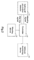
- Fig. 2 schematically shows a device for adjusting the view range of a vehicular monitoring device according to a second embodiment of the present invention.
- the device includes a getting-off pre-motion detector 21 and a controller 22 in communication with the getting-off pre-motion detector 21 and the vehicular monitoring device 23 such as a rearview mirror, a camera and/or a display.
- the getting-off pre-motion detector 21 detects, for example, the enabling of the emergency flasher switch, zero velocity of the vehicle, the turning-off of the engine, or the entering of the parking gear, it frequently implies that there would be people getting off the vehicle. Therefore, the getting-off pre-motion detector 21 outputs an adjusting signal to the controller 22.
- the controller 22 controls the movement of the rearview mirror 23 between an initial position and a working position in response to the adjusting signal.
- the definition of movement is similar to that described in the first embodiment.
- the vehicular monitoring device After the movement of the vehicular monitoring device form the initial position to the working position in response to the above-described pre-motion operation has been done, the vehicular monitoring device should return to the initial position. For example, when the emergency flasher switch is disabled, the vehicle has a non-zero velocity, the engine is started, or the parking gear is disengaged. Meanwhile, a recovering signal is outputted from the pre-motion detector 21 to the controller 22 to have the vehicular monitoring device return to the initial position.
- the recovery of the vehicular monitoring device can also be determined by timing. For example, the vehicular monitoring device is moved toward the initial position in a few seconds after the vehicular monitoring device reaches the working position.
- the pre-motion detector 11 or 21 can also output a warning signal to the controller 11 or 21 in addition to the adjusting signal.
- the controller 11 or 21 enables a warning device 14 or 24 in response to the warning signal for safety purpose. For example, the horn sounds or the vehicular lamp twinkles in a desired pattern.
- the functions of the pre-motion detector 11 or 21 and the controller 12 or 22 can be performed by a micro-controller in a way of programs.
- the automatic view-angle adjusting function can be designed as a basic response of the vehicle.
- the function can be enabled by pressing a key or a button.
- the movement speed of the vehicular monitoring device between the initial position and any of the working positions depends on the velocity of the vehicle.
- a vehicular digital bus such as a controller area network (CAN) or a vehicular area network (VAN) bus is preferred used to transfer signals.
- CAN controller area network
- VAN vehicular area network
Landscapes
- Engineering & Computer Science (AREA)
- Multimedia (AREA)
- Mechanical Engineering (AREA)
- Traffic Control Systems (AREA)
- Rear-View Mirror Devices That Are Mounted On The Exterior Of The Vehicle (AREA)
- Closed-Circuit Television Systems (AREA)
- Emergency Alarm Devices (AREA)
Abstract
Description
- The present invention relates to a view-range adjusting device, and more particular to a device for adjusting the view range of a vehicular monitoring device in response to a pre-motion operation. The present invention also relates to a method for adjusting a vehicular monitoring device.
- When a driver is seated in a vehicle, he should adjust all of the interior and exterior rearview mirrors according to his need. The rearview mirror can be adjusted manually or automatically by pushing buttons. After the adjustment of rearview mirrors is done, the view angle of each rearview mirror seen by the driver is constant, and it is difficult and also dangerous for the driver to further change the view angles while driving.
- In practice, when a driver would like to change to another lane, turn to another direction or overtaking a car, he will need to realize more about the situation of the adjacent lane to see whether there is any vehicle oncoming. Therefore, the horizontally turning of the rearview mirror toward the target lane will be helpful for the lane-changing or overtaking operation. In addition, while moving up or down a slope, it is advantageous to turn the rearview mirror vertically to obtain a view range similar to that on the flat road.
- Aside from the above situations, there are more situations needing a proper view range different from that required in the normal driving mode.
- Therefore, an object of the present invention is to provide a device and a method for adjusting the view range of the rearview mirror in various cases so as to provide a suitable view range for the driver.
- A first aspect of the present invention relates to a device for adjusting a view range of a vehicular monitoring device. The device comprises an overtaking pre-motion detector outputting an adjusting signal when an overtaking operation is predicted; and a controller in communication with the overtaking pre-motion detector and the vehicular monitoring device, controlling the vehicular monitoring device to move in response to the adjusting signal.
- Preferably, the overtaking pre-motion detector further outputs a warning signal to a video and/or audio warning device when the overtaking operation is predicted.
- For example, the warning device is a horn which sounds in a desired pattern in response to the warning signal. For another example, the warning device is a vehicular lamp which twinkles in a desired pattern in response to the warning signal.
- The overtaking pre-motion detector outputs the adjusting signal, for example, when the over-drive (OD) gear is shut off, when the revolving speed of the engine exceeds a threshold value, when the acceleration of the vehicle exceeds a threshold value or when a specific light signal is outputted by the vehicular lamp or lamps.
- Preferably, the controller asserts a recovering signal to the vehicular monitoring device to force the vehicular monitoring device to return to an initial position suitable for the normal driving mode when an emergency state is determined.
- The emergency state, for example, can be determined when emergency brake is done, when the anti-lock brake system (ABS) is enabled, or when the traction control system is enabled.
- In an embodiment, the controller asserts a recovering signal to have the vehicular monitoring device return to an initial position suitable for the normal driving mode when the OD gear is entered again, the revolving speed of the engine changes to a level below the threshold value, the acceleration of the vehicle is lowered, or the specific light signal is stopped for a predetermined period of time.
- Alternatively, the controller asserts a recovering signal to have the vehicular monitoring device move toward an initial position suitable for the normal driving mode in a predetermined period of time after the vehicular monitoring device reaches a working position suitable for overtaking motion.
- A second aspects of the present invention relates to a device for adjusting a view range of a vehicular monitoring device, comprising a getting-off pre-motion detector outputting an adjusting signal when a getting-off operation is predicted; and a controller in communication with the getting-off pre-motion detector and the vehicular monitoring device, controlling the vehicular monitoring device to move in response to the adjusting signal.
- The getting-off pre-motion detector outputs the adjusting signal in response to the enabling of the emergency flasher switch, the substantially zero velocity of the vehicle, the turning-off of the engine or the entering of the parking gear.
- In an embodiment, the controller asserts a recovering signal to have the vehicular monitoring device return to an initial position suitable for the normal driving mode when the emergency flasher switch is disabled, the vehicle has a non-zero velocity, the engine is started, or the parking gear is disengaged. Alternatively, the controller asserts a recovering signal to have the vehicular monitoring device move toward an initial position suitable for the normal driving mode in a predetermined period of time after the vehicular monitoring device reaches a working position suitable for overtaking motion.
- A third aspects of the present invention relates to a method for adjusting a view range of a vehicular monitoring device. The method comprises steps of detecting a status of a vehicle; determining whether a pre-motion operation is performed according to the status of the vehicle; outputting an adjusting signal to move the vehicular monitoring device between an initial position and a working position when the pre-motion operation is performed; and outputting a warning signal to enable a warning device when the pre-motion operation is performed.
- In an embodiment, the pre-motion operation is an overtaking pre-motion operation. For example, the pre-motion operation is to shut off the over-drive (OD) gear, to significantly step on the accelerator, to sudden change up the vehicle, or to output a specific light signal.
- In an embodiment, the pre-motion operation is a getting-off pre-motion operation. For example, the pre-motion operation is to enable the emergency flasher switch, to zero the velocity of the vehicle, to turn off of the engine, or to enter the parking gear.
- The present invention may best be understood through the following description with reference to the accompanying drawings, in which:
- Fig. 1 is a schematic block diagram showing a device for adjusting the view range of a vehicular monitoring device according to a first embodiment of the present invention; and
- Fig. 2 is a schematic block diagram showing a device for adjusting the view range of a vehicular monitoring device according to a second embodiment of the present invention.
-
- Please refer to Fig. 1 which schematically shows a device for adjusting the view range of a vehicular monitoring device according to a first embodiment of the present invention. The device includes a overtaking pre-motion
detector 11 and acontroller 12 in communication with the overtaking pre-motiondetector 11 and thevehicular monitoring device 13 such as a rearview mirror, a camera and/or a display. The camera, for example, can be a CCD or CMOS camera. The display, for example, can be a liquid crystal display. When the overtaking pre-motiondetector 11 detects the over-drive (OD) gear is shut off, the revolving speed of the engine exceeds a threshold value, which for example can be achieved by significantly stepping on the accelerator, the vehicle suddenly changes up, or a specific light signal known to the public is outputted, e.g. the twinkling of the headlamp, it is predicted that an overtaking operation is ready to launch. Meanwhile, the overtaking pre-motiondetector 11 outputs an adjusting signal to thecontroller 12. Thecontroller 12 then controls the movement of therearview mirror 13 between an initial position and a working position in response to the adjusting signal. - Herein and hereinafter, the term "move", "moving", "moved" or "movement" broadly means the change of the vehicular monitoring device on location, orientation, focus, zooming effect etc., due to for example shift, rotation, pivoting or the combination thereof, in order to obtain a suitable view range. The movement between the initial position and the working position may indicate the single trip from the initial position to the working position suitable for the overtaking motion or the signal trip from the working position to the initial position suitable for normal driving mode. Alternatively, the movement between the initial position and the working position may be a to-and-fro scanning motion or a two-dimensional motion, depending on practice.
- During the movement of the vehicular monitoring device from the initial position to working position, the vehicular monitoring device is preferably forced to return to the initial position if an emergency state occurs. For example, the emergency state is determined when emergency brake is done, when the Anti-lock brake system (ABS) or the traction control system is enabled, etc.
- After the movement of the vehicular monitoring device form the initial position to the working position in response to the above-described pre-motion operation has been done, the vehicular monitoring device should return to the initial position. For example, when the
pre-motion detector 11 detects that the OD gear is entered again, the revolving speed of the engine changes below the threshold value, the acceleration of the vehicle is lowered, or the specific light signal is stopped for a predetermined period of time, a recovering signal is outputted from thepre-motion detector 11 to thecontroller 12 to have the vehicular monitoring device return to the initial position. - Please refer to Fig. 2 which schematically shows a device for adjusting the view range of a vehicular monitoring device according to a second embodiment of the present invention. The device includes a getting-off pre-motion
detector 21 and acontroller 22 in communication with the getting-off pre-motiondetector 21 and thevehicular monitoring device 23 such as a rearview mirror, a camera and/or a display. When the getting-off pre-motiondetector 21 detects, for example, the enabling of the emergency flasher switch, zero velocity of the vehicle, the turning-off of the engine, or the entering of the parking gear, it frequently implies that there would be people getting off the vehicle. Therefore, the getting-off pre-motiondetector 21 outputs an adjusting signal to thecontroller 22. Thecontroller 22 then controls the movement of therearview mirror 23 between an initial position and a working position in response to the adjusting signal. The definition of movement is similar to that described in the first embodiment. - After the movement of the vehicular monitoring device form the initial position to the working position in response to the above-described pre-motion operation has been done, the vehicular monitoring device should return to the initial position. For example, when the emergency flasher switch is disabled, the vehicle has a non-zero velocity, the engine is started, or the parking gear is disengaged. Meanwhile, a recovering signal is outputted from the
pre-motion detector 21 to thecontroller 22 to have the vehicular monitoring device return to the initial position. - For the above embodiments, the recovery of the vehicular monitoring device can also be determined by timing. For example, the vehicular monitoring device is moved toward the initial position in a few seconds after the vehicular monitoring device reaches the working position.
- For the above embodiments, the
pre-motion detector controller controller warning device - For the above embodiments, the functions of the
pre-motion detector controller - It is to be noted that the automatic view-angle adjusting function can be designed as a basic response of the vehicle. Alternatively, the function can be enabled by pressing a key or a button.
- In another aspect of the present invention, preferably, the movement speed of the vehicular monitoring device between the initial position and any of the working positions depends on the velocity of the vehicle. The faster the vehicle runs, the faster the vehicular monitoring device moves. As such, the driver can realize the environment situation quickly. For efficiently achieving the above purpose, a vehicular digital bus such as a controller area network (CAN) or a vehicular area network (VAN) bus is preferred used to transfer signals.
- The features disclosed in the foregoing description, in the claims and/or in the accompanying drawings may, both separately and in any combination thereof, be material for realising the invention in diverse forms thereof.
Claims (22)
- A device for adjusting a view range of a vehicular monitoring device, comprising:an overtaking pre-motion detector outputting an adjusting signal when an overtaking operation is predicted; anda controller in communication with said overtaking pre-motion detector and said vehicular monitoring device, controlling said vehicular monitoring device to move in response to said adjusting signal.
- The device according to claim 1 wherein said overtaking pre-motion detector further outputs a warning signal to a video and/or audio warning device when said overtaking operation is predicted.
- The device according to claim 1 wherein said overtaking pre-motion detector outputs said adjusting signal when the over-drive (OD) gear is shut off, when the revolving speed of the engine exceeds a threshold value, when the acceleration of the vehicle exceeds a threshold value, or when a specific light signal is outputted by the vehicular lamp or lamps.
- The device according to claim 1 wherein said vehicular monitoring device is a rearview mirror, a camera or a display.
- The device according to claim 1 wherein a movement speed of said vehicular monitoring device between an initial position and a working position depends on a velocity of the vehicle.
- The device according to claim 1 further comprising a vehicular digital bus for communicating said overtaking pre-motion detector with said controller.
- The device according to claim 1 wherein said controller asserts a recovering signal to said vehicular monitoring device to force said vehicular monitoring device to return to an initial position suitable for the normal driving mode when an emergency state is determined.
- The device according to claim 7 wherein said emergency state is determined when emergency brake is done, when the anti-lock brake system (ABS) is enabled, when the traction control system is enabled.
- The device according to claim 1 wherein said controller asserts a recovering signal to have said vehicular monitoring device return to an initial position suitable for the normal driving mode when the OD gear is entered again, the revolving speed of the engine changes to a level below the threshold value, the acceleration of the vehicle is lowered, or the specific light signal is stopped for a predetermined period of time.
- The device according to claim 1 wherein said controller asserts a recovering signal to have said vehicular monitoring device move toward an initial position suitable for the normal driving mode in a predetermined period of time after the vehicular monitoring device reaches a working position suitable for overtaking motion.
- A device for adjusting a view range of a vehicular monitoring device, comprising:a getting-off pre-motion detector outputting an adjusting signal when a getting-off operation is predicted; anda controller in communication with said getting-off pre-motion detector and said vehicular monitoring device, controlling said vehicular monitoring device to move in response to said adjusting signal.
- The device according to claim 11 wherein said getting-off pre-motion detector further outputs a warning signal to a video and/or audio warning device when said getting-off operation is predicted.
- The device according to claim 11 wherein said getting-off pre-motion detector outputs said adjusting signal in response to the enabling of the emergency flasher switch, substantially zero velocity of the vehicle, the turning-off of the engine or the entering of the parking gear.
- The device according to claim 11 wherein said controller asserts a recovering signal to said vehicular monitoring device to force said vehicular monitoring device to return to an initial position suitable for the normal driving mode when an emergency state is determined.
- The device according to claim 11 wherein said emergency state is determined when emergency brake is done, or the anti-lock brake system (ABS) or the traction control system is enabled.
- The device according to claim 11 wherein said controller asserts a recovering signal to have said vehicular monitoring device return to an initial position suitable for the normal driving mode when the emergency flasher switch is disabled, the vehicle has a non-zero velocity, the engine is started, the parking gear is disengaged, or in a predetermined period of time after the vehicular monitoring device reaches a working position suitable for overtaking motion.
- A method for adjusting a view range of a vehicular monitoring device, comprising:detecting a status of a vehicle;determining whether a pre-motion operation is performed according to said status of said vehicle;outputting an adjusting signal to move said vehicular monitoring device between an initial position and a working position when said pre-motion operation is performed; andoutputting a warning signal to enable a warning device when said pre-motion operation is performed.
- The method according to claim 17 wherein said pre-motion operation is an overtaking pre-motion operation, and said pre-motion operation is to shut off the over-drive (OD) gear, to significantly step on the accelerator, to sudden change up the vehicle, or to output a specific light signal.
- The method according to claim 17 wherein said pre-motion operation is a getting-off pre-motion operation. And said pre-motion operation is to enable the emergency flasher switch, to zero the velocity of the vehicle, to turn off of the engine, or to enter the parking gear.
- The method according to claim 17 wherein said vehicular monitoring device is moved by a single trip from an initial position to a working position or a to-and-fro scanning mode between said initial position and said working position when said pre-motion operation is performed.
- The method according to claim 17 wherein said vehicular monitoring device is moved in two dimensions.
- The method according to claim 17 wherein said warning device is a vehicular horn which sounds in a desired pattern in response to said warning signal or a vehicular lamp which twinkles in a desired pattern in response to said warning signal.
Applications Claiming Priority (2)
| Application Number | Priority Date | Filing Date | Title |
|---|---|---|---|
| CN02105275.1A CN1413860A (en) | 2002-02-25 | 2002-02-25 | Device and method for regulating angle of automobile exterior state monitor |
| CN02105275 | 2002-02-25 |
Publications (2)
| Publication Number | Publication Date |
|---|---|
| EP1338472A2 true EP1338472A2 (en) | 2003-08-27 |
| EP1338472A3 EP1338472A3 (en) | 2004-12-29 |
Family
ID=4740169
Family Applications (2)
| Application Number | Title | Priority Date | Filing Date |
|---|---|---|---|
| EP03004084A Withdrawn EP1338473A3 (en) | 2002-02-25 | 2003-02-25 | Device and method for adjusting view range of vehicular monitoring device |
| EP03004074A Withdrawn EP1338472A3 (en) | 2002-02-25 | 2003-02-25 | Device and method for adjusting view range of vehicular monitoring device |
Family Applications Before (1)
| Application Number | Title | Priority Date | Filing Date |
|---|---|---|---|
| EP03004084A Withdrawn EP1338473A3 (en) | 2002-02-25 | 2003-02-25 | Device and method for adjusting view range of vehicular monitoring device |
Country Status (4)
| Country | Link |
|---|---|
| US (1) | US6900739B2 (en) |
| EP (2) | EP1338473A3 (en) |
| JP (2) | JP2003285688A (en) |
| CN (1) | CN1413860A (en) |
Families Citing this family (16)
| Publication number | Priority date | Publication date | Assignee | Title |
|---|---|---|---|---|
| US7571041B2 (en) * | 2005-01-13 | 2009-08-04 | General Motors Corporation | Automatic control of automotive rearview mirror |
| JP2006321265A (en) * | 2005-05-17 | 2006-11-30 | Honda Lock Mfg Co Ltd | Back visual range correction control device of vehicle |
| CN100453365C (en) * | 2006-03-17 | 2009-01-21 | 财团法人工业技术研究院 | Method and device for rearview mirror assistant controlling of the vehicle |
| DE102006055344A1 (en) * | 2006-11-23 | 2008-05-29 | Vdo Automotive Ag | Method for wireless communication between vehicles |
| JP4748111B2 (en) * | 2007-05-31 | 2011-08-17 | 株式会社デンソー | Obstacle detection device |
| KR20100009970U (en) * | 2009-04-01 | 2010-10-11 | 주식회사 케이엠씨 | Tilting apparatus of monitor for vehicle |
| CN102555915A (en) * | 2010-12-15 | 2012-07-11 | 上海工程技术大学 | Method and device for adjusting visible angle of rearview mirror based on vehicle speed and turning angle |
| EP2780197A1 (en) * | 2011-11-15 | 2014-09-24 | Continental Automotive Systems, Inc. | Rear view camera display during braking |
| CN103241189A (en) * | 2012-02-13 | 2013-08-14 | 环达电脑(上海)有限公司 | Automatic steering control device |
| JP5411976B1 (en) * | 2012-09-21 | 2014-02-12 | 株式会社小松製作所 | Work vehicle periphery monitoring system and work vehicle |
| CN106515579B (en) * | 2015-09-10 | 2018-12-18 | 奥迪股份公司 | The blind spot region of vehicle monitors |
| KR101702888B1 (en) * | 2015-10-12 | 2017-02-06 | 현대자동차주식회사 | Vehicle view angle controlling apparatus, vehicle having the same and vehicle view angle controlling method |
| CN106772334B (en) * | 2015-11-24 | 2019-07-05 | 同济大学 | A kind of attitude control method of Vehicle radar |
| CN105966315B (en) * | 2016-05-20 | 2018-05-08 | 周远航 | A kind of spacing determination methods based on automobile rearview mirror |
| CN108725319B (en) * | 2017-10-31 | 2021-05-04 | 无锡职业技术学院 | Image type car backing guidance method |
| KR20200123953A (en) * | 2019-04-23 | 2020-11-02 | 현대자동차주식회사 | Method for Operate the Inside Display Mirror |
Citations (6)
| Publication number | Priority date | Publication date | Assignee | Title |
|---|---|---|---|---|
| JPH08223566A (en) * | 1995-02-10 | 1996-08-30 | Hitachi Ltd | Surrounding state recognition device for vehicle |
| US5680123A (en) * | 1996-08-06 | 1997-10-21 | Lee; Gul Nam | Vehicle monitoring system |
| EP1033694A2 (en) * | 1999-03-01 | 2000-09-06 | Yazaki Corporation | Rear-view monitoring system for vehicles |
| EP1114750A2 (en) * | 2000-01-05 | 2001-07-11 | Robert Bosch Gmbh | Vehicle rear view mirror positioning device |
| DE10016222A1 (en) * | 2000-03-31 | 2001-10-31 | Volkswagen Ag | Electrical adjustment of outside mirror of motor vehicle when changing lanes based on angle at which change is made |
| JP2001310679A (en) * | 2000-04-28 | 2001-11-06 | Isuzu Motors Ltd | Rearview mirror device |
Family Cites Families (13)
| Publication number | Priority date | Publication date | Assignee | Title |
|---|---|---|---|---|
| US4746206A (en) * | 1986-11-12 | 1988-05-24 | Kusztos John E | Motorcycle with automatically adjustable mirror to reduce image movement |
| US5126885A (en) * | 1990-06-18 | 1992-06-30 | Westech Innovations Inc. | Control device for electrically controlled rearview mirror |
| US5027200A (en) * | 1990-07-10 | 1991-06-25 | Edward Petrossian | Enhanced viewing at side and rear of motor vehicles |
| US5463384A (en) * | 1991-02-11 | 1995-10-31 | Auto-Sense, Ltd. | Collision avoidance system for vehicles |
| JPH08167100A (en) * | 1994-12-12 | 1996-06-25 | Hisaji Nakamura | Steering device |
| US6389340B1 (en) * | 1998-02-09 | 2002-05-14 | Gary A. Rayner | Vehicle data recorder |
| KR20000004717U (en) * | 1998-08-14 | 2000-03-15 | 안문휘 | Reflector auto-adjustment side mirror |
| DE19904778C2 (en) * | 1999-02-05 | 2001-04-12 | Mekra Lang Gmbh & Co Kg | System for automatic exterior mirror adjustment when cornering vehicles |
| US6193380B1 (en) * | 1999-04-20 | 2001-02-27 | Raymond A. Jacobs | Vehicle blind spot mirror |
| JP2001294086A (en) * | 2000-04-17 | 2001-10-23 | Auto Network Gijutsu Kenkyusho:Kk | Vehicle peripheral vision confirming device |
| JP4598239B2 (en) * | 2000-06-07 | 2010-12-15 | アイシン精機株式会社 | Parking assistance device |
| JP3619753B2 (en) * | 2000-07-03 | 2005-02-16 | トヨタ自動車株式会社 | Rear view display device for moving object |
| US6485155B1 (en) * | 2001-07-06 | 2002-11-26 | Bernard Duroux | Multiplexing mirror |
-
2002
- 2002-02-25 CN CN02105275.1A patent/CN1413860A/en active Pending
-
2003
- 2003-02-24 JP JP2003046366A patent/JP2003285688A/en active Pending
- 2003-02-25 US US10/374,160 patent/US6900739B2/en not_active Expired - Fee Related
- 2003-02-25 EP EP03004084A patent/EP1338473A3/en not_active Withdrawn
- 2003-02-25 JP JP2003046766A patent/JP2003291757A/en active Pending
- 2003-02-25 EP EP03004074A patent/EP1338472A3/en not_active Withdrawn
Patent Citations (6)
| Publication number | Priority date | Publication date | Assignee | Title |
|---|---|---|---|---|
| JPH08223566A (en) * | 1995-02-10 | 1996-08-30 | Hitachi Ltd | Surrounding state recognition device for vehicle |
| US5680123A (en) * | 1996-08-06 | 1997-10-21 | Lee; Gul Nam | Vehicle monitoring system |
| EP1033694A2 (en) * | 1999-03-01 | 2000-09-06 | Yazaki Corporation | Rear-view monitoring system for vehicles |
| EP1114750A2 (en) * | 2000-01-05 | 2001-07-11 | Robert Bosch Gmbh | Vehicle rear view mirror positioning device |
| DE10016222A1 (en) * | 2000-03-31 | 2001-10-31 | Volkswagen Ag | Electrical adjustment of outside mirror of motor vehicle when changing lanes based on angle at which change is made |
| JP2001310679A (en) * | 2000-04-28 | 2001-11-06 | Isuzu Motors Ltd | Rearview mirror device |
Non-Patent Citations (2)
| Title |
|---|
| PATENT ABSTRACTS OF JAPAN vol. 1996, no. 12, 26 December 1996 (1996-12-26) & JP 8 223566 A (HITACHI LTD; NISSAN MOTOR CO LTD), 30 August 1996 (1996-08-30) * |
| PATENT ABSTRACTS OF JAPAN vol. 2002, no. 03, 3 April 2002 (2002-04-03) & JP 2001 310679 A (ISUZU MOTORS LTD), 6 November 2001 (2001-11-06) * |
Also Published As
| Publication number | Publication date |
|---|---|
| EP1338473A3 (en) | 2004-12-29 |
| JP2003291757A (en) | 2003-10-15 |
| EP1338472A3 (en) | 2004-12-29 |
| US6900739B2 (en) | 2005-05-31 |
| EP1338473A2 (en) | 2003-08-27 |
| CN1413860A (en) | 2003-04-30 |
| US20030160685A1 (en) | 2003-08-28 |
| JP2003285688A (en) | 2003-10-07 |
Similar Documents
| Publication | Publication Date | Title |
|---|---|---|
| US6900739B2 (en) | Device and method for adjusting view range of vehicular monitoring device | |
| US10228698B2 (en) | Vehicle control system, vehicle control method, and vehicle control program | |
| JP2018524730A (en) | Braking light detection of a vehicle traveling forward to adapt the operation of an active safety mechanism | |
| JP7014214B2 (en) | Driving support device | |
| US7012510B2 (en) | Device and method for adjusting view range of vehicular monitoring device | |
| CN111065547A (en) | Irradiation apparatus and irradiation method | |
| JPH097099A (en) | Alarm device | |
| CN108016353B (en) | Door opening pre-detection system for vehicle | |
| JP2005149021A (en) | Device for assessing possibility of collision | |
| JP2001315547A (en) | Vehicular head-up display device | |
| JPH06227318A (en) | Rearview monitoring device of vehicle and method thereof | |
| WO2019176391A1 (en) | Drive recorder, display control method, and program | |
| JP6952110B2 (en) | Control method of turn signal and control device of turn signal | |
| JP2009507707A (en) | Method for warning the driver of a car equipped with a travel speed adjustment system | |
| JP2018086874A (en) | Following-start control apparatus of vehicle | |
| JP7044000B2 (en) | Vehicle control device and vehicle control method | |
| JP4337131B2 (en) | Mobile control device | |
| US20030191569A1 (en) | Vehicular monitor actuating device and method | |
| JP4635226B2 (en) | Vehicle control device | |
| EP1332927A2 (en) | Vehicular wireless transmission control assembly | |
| JP2002178785A (en) | Vehicle start control device | |
| EP1356989B1 (en) | Device and method for actuating and positioning vehicular monitoring device | |
| JP2003205763A (en) | Travel controller | |
| JP2022127994A (en) | vehicle control system | |
| JP2003300441A (en) | Rear vision display device for vehicle |
Legal Events
| Date | Code | Title | Description |
|---|---|---|---|
| PUAI | Public reference made under article 153(3) epc to a published international application that has entered the european phase |
Free format text: ORIGINAL CODE: 0009012 |
|
| AK | Designated contracting states |
Designated state(s): AT BE BG CH CY CZ DE DK EE ES FI FR GB GR HU IE IT LI LU MC NL PT SE SI SK TR |
|
| AX | Request for extension of the european patent |
Extension state: AL LT LV MK RO |
|
| PUAL | Search report despatched |
Free format text: ORIGINAL CODE: 0009013 |
|
| 17P | Request for examination filed |
Effective date: 20041008 |
|
| AK | Designated contracting states |
Kind code of ref document: A3 Designated state(s): AT BE BG CH CY CZ DE DK EE ES FI FR GB GR HU IE IT LI LU MC NL PT SE SI SK TR |
|
| AX | Request for extension of the european patent |
Extension state: AL LT LV MK RO |
|
| 17Q | First examination report despatched |
Effective date: 20050502 |
|
| AKX | Designation fees paid |
Designated state(s): AT BE BG CH CY CZ DE DK EE ES FI FR GB GR HU IE IT LI LU MC NL PT SE SI SK TR |
|
| STAA | Information on the status of an ep patent application or granted ep patent |
Free format text: STATUS: THE APPLICATION IS DEEMED TO BE WITHDRAWN |
|
| 18D | Application deemed to be withdrawn |
Effective date: 20050913 |