JP4635226B2 - Vehicle control device - Google Patents
Vehicle control device Download PDFInfo
- Publication number
- JP4635226B2 JP4635226B2 JP2001160966A JP2001160966A JP4635226B2 JP 4635226 B2 JP4635226 B2 JP 4635226B2 JP 2001160966 A JP2001160966 A JP 2001160966A JP 2001160966 A JP2001160966 A JP 2001160966A JP 4635226 B2 JP4635226 B2 JP 4635226B2
- Authority
- JP
- Japan
- Prior art keywords
- vehicle
- alarm
- obstacle
- driver
- detected
- Prior art date
- Legal status (The legal status is an assumption and is not a legal conclusion. Google has not performed a legal analysis and makes no representation as to the accuracy of the status listed.)
- Expired - Fee Related
Links
Images


Landscapes
- Control Of Vehicle Engines Or Engines For Specific Uses (AREA)
- Traffic Control Systems (AREA)
- Regulating Braking Force (AREA)
- Control Of Driving Devices And Active Controlling Of Vehicle (AREA)
- Controls For Constant Speed Travelling (AREA)
Description
【0001】
【発明の属する技術分野】
本発明は、自車両の前方に存在する障害物に関する警報を発生する警報装置の分野に関する。
【0002】
【従来の技術】
従来より、代表的な車両である自動車の分野においては、前方に存在する障害物に関する警報をドライバに対して発する各種の警報装置が提案されている。
【0003】
このような警報装置の一例として、例えば特開平11−189071号には、車線逸脱の防止制御と、前方を走行する他車両との車間距離制御とを行なうと共に、それら制御の状態を車両内において適宜表示する前方障害物警報システムが提案されている。
【0004】
【発明が解決しようとする課題】
上記従来の技術によれば、車線逸脱を防止することができると共に、安全な車間距離を維持することができるが、複数の事象に対しての警報動作が行われるため、それらの警報が発報された際に、ドライバはどの警報が発報しているのかを瞬間的には判断できない場合がある。
【0005】
また、このような車両用の警報システムでは、ドライバによる運転操作とは独立して、走行中の車両が自動的に制動するため、ドライバは違和感を感じる場合が多い。
【0006】
そこで本発明は、ドライバが容易に認識可能な動作態様で、自車両の前方に存在する障害物に関する警報を行なうと共に、適切な自動制動を行なう車両用制御装置の提供を目的とする。
【0007】
【課題を解決するための手段】
上記の目的を達成するため、本発明に係る車両用制御装置は、以下の構成を特徴とする。
【0008】
即ち、前方に存在する障害物と車両との距離に関する値を検出する障害物検出手段と、前記車両のドライバによる運転操作とは独立して、前記車両の走行速度を自動的に制動する制動制御手段と、前記距離に関する値が所定の条件を満たす際に、前記制動制御手段による前記車両に対する制動力が所定周期で増減するように調整すると共に、その制動力のベース値を、時間の経過に応じて漸増するように変更することにより、前記ドライバに対する障害物警報を行なう警報手段とを備えることを特徴とする。
【0009】
好適な実施形態において、前記警報手段は、前記障害物警報を行なっているときに前記ドライバによるブレーキ操作を検出した際には、前記障害物警報を中止すると良い。
【0010】
また、例えば前記警報手段は、前記障害物警報を行なっているときに、前記車両が所定勾配より急な下り勾配を走行していることを検出した際には、前記ドライバによるブレーキ操作を検出しても、前記障害物警報を継続すると良い。
【0011】
或いは、前記警報手段は、前記障害物警報を行なっているときに、前記車両が所定勾配より急な下り勾配を走行していることを検出した際には、前記ドライバによる所定の強さより大きなブレーキ操作が検出されない限り、前記障害物警報を継続させても良い。
【0012】
また、好適な他の実施形態において、前記制動制御手段は、前記警報手段による障害物警報が行われている場合に、前記ドライバによるブレーキ操作を検出した際には、前記警報手段による調整結果としての制動力を保持したままの状態で、前記ドライバによるブレーキ操作に応じた制動を行なうと良い。
【0013】
また、例えば前記警報手段は、前記ベース値の大きさを、前記障害物と前記車両との距離に関する値、前記車両の運転状態を表わすパラメータ、前記車両周囲の走行路環境を表わすパラメータの少なくとも何れかに応じて変更すると良い。
【0014】
この場合、前記警報手段は、前記ベース値の大きさを、前記障害物との衝突危険度に関するパラメータ、前記ドライバの前方視認性の度合に関するパラメータ、そして前記車両の走行安定性に関するパラメータの優先順位で変更すると良い。
【0015】
【発明の効果】
上記の本発明によれば、ドライバが容易に認識可能な動作態様で、自車両の前方に存在する障害物に関する警報を行なうと共に、適切な自動制動を行なう車両用制御装置の提供が実現する。
【0016】
即ち、請求項1の発明によれば、自動的な制動動作によって体感的な警報を行なう際に、制動力が所定周期で増減すると共に、その制動力のベース値が時間の経過に応じて漸増する、という動作態様なので、適切な自動制動を行なうことができると共に、ドライバは、前方障害物に対する警報であることを容易に認識することができる。
【0017】
また、請求項2の発明によれば、ドライバによるブレーキ操作が行なわれているときには自動的な制動を伴う障害物警報が中止されるので、そのブレーキ操作中にも係る障害物警報が実行されることによるドライバの違和感を防止することができる。
【0018】
また、一般に、急な下り勾配においては、前方に障害物が存在するか否かに関らずに、ドライバはブレーキ操作によって走行速度の調整を行なう場合が多いが、請求項3の発明によれば、急な下り勾配を走行中には、ドライバによるブレーキ操作を検出した場合であっても障害物警報が継続されるので、障害物警報が動作していることを、ドライバに対して確実に報知することができる。
【0019】
また、上記の如くドライバがブレーキ操作によって走行速度の調整を行なう急な下り勾配において、ドライバによるブレーキ操作は、さほど大きな強さ(例えばブレーキペダルに対する踏力)ではないが、請求項4の発明によれば、ドライバによる所定の強さより大きなブレーキ操作が検出されない限り、障害物警報が継続される。即ち、ドライバが前方に存在する障害物を認識して大きな強さでブレーキ操作を行なった場合には、障害物警報が中止される。これにより、障害物警報が動作していることをドライバに対して確実に報知することができると共に、そのブレーキ操作中にも係る障害物警報が実行されることによるドライバの違和感を防止することができる。
【0020】
また、請求項5の発明によれば、ドライバによるブレーキ操作中にも制動力が増減することによるドライバの違和感を防止することができると共に、ドライバによる障害物認識後のブレーキ操作の不足による危険な状態を確実に補うことができる。
【0021】
また、請求項6の発明によれば、自動的な制動動作の度合いを適切に調整することができる。
【0022】
また、請求項7の発明によれば、自動的な制動動作の度合いを、危険性に応じて適切に調整することができる。
【0023】
【発明の実施の形態】
以下、本発明に係る車両用制御装置を、前方障害物への衝突防止支援システムに適用した実施形態として、図面を参照して詳細に説明する。
【0024】
[第1の実施形態]
本実施形態において、衝突防止支援システムは、自車両の前方に存在する障害物への衝突を防止すべく、当該自車両において表示及び音声(音響)によって警報を発生すると共に、後述する如く自動的な制動を行なうことにより、ドライバが体感可能な警報(体感警報)を行なう。本実施形態において、体感警報とは、ドライバが運転中の車両が所定の制動態様の自動的な制動動作によって減速することにより、その減速の際の自車両の挙動変化により、当該ドライバが自車両の前方に存在する障害物に関する衝突の危険性が報知されていることを、体感によって認識できる警報である。
【0025】
まず、本実施形態における特徴的な体感警報制御を説明するのに先立って、衝突防止支援システムの基本的な動作について説明する。
【0026】
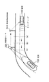
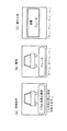
図1は、第1の実施形態における前方障害物への衝突防止支援システムの動作を説明する図である。また、図2は、第1の実施形態における前方障害物への衝突防止支援システムによって車両上で報知される警報の態様を説明する図である。
【0027】
本実施形態において、車両100の走行路には、道路側に設けられた所定の設備(所謂インフラ)として、障害物の有無及び存在する障害物までの距離を検出する障害物センサ200、並びに、その障害物センサ200による検出結果や路面の状態等の情報を、周囲を走行する車両100に送信する路車間通信設備300が設けられている。また、車両100には、前方に存在する障害物と自車両との距離を検出するレーザレーダ3が設けられている。
【0028】
車両100の制御装置(後述するメインコントローラ1に相当)は、前方に障害物が存在する場合に、その障害物と自車両との距離を、路車間通信設備300またはレーザレーダ3から取得する。
【0029】
そして、車両100の制御装置は、取得した距離に応じて、
・まず、障害物までの距離に比較的余裕のある場合には、図2(a)に例示するように、障害物の存在を知らせるための情報提供を、ディスプレイ(後述するディスプレイ12に相当)への表示と人工音声によって行ない、
・次に、障害物までの距離に余裕がない場合には、図2(b)に例示するように、その旨をディスプレイへの表示と警報音によって行ない、
・そして、障害物との衝突を回避するためには直ちに制動が必要な場合には、図2(c)に例示するように、その旨をディスプレイへの表示と警報音によって報知すると共に、体感警報として、車両100の自動的な制動を実行することにより、ドライバの運転操作を支援する。
【0030】
次に、上記の衝突防止支援システムを実現するために車両100に搭載される装備について説明する。
【0031】
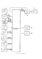
図3は、第1の実施形態における車両100に搭載される主な機器の配置を例示する図である。また、図4は、第1の実施形態における車両100の制御系の構成を示すブロック図である。
【0032】
図3及び図4において、前後加速度(G)センサ2は、車両100に発生する車両前後方向への加速を検出する。レーザレーダ3は、車両100の前方に存在する障害物と車両100との距離及び相対速度を検出する。路車間通信機4は、路車間通信設備300から送出された電波を受信することにより、道路設備側から前方に存在する障害物までの距離及び相対速度、渋滞や工事等の道路情報、並びに路面摩擦係数(μ)等の路面情報を取得する。
【0033】
また、ブレーキスイッチ5は、ドライバによるブレーキペダルの操作の有無を検出する。ブレーキ圧センサ6は、ドライバによるブレーキペダルの操作力(踏力)を検出する。
【0034】
また、ナビゲーションユニット7は、メインコントローラ1に対して、前方の道路形状等を表わす道路情報を提供する。GPSユニット8は、外部より受信したGPS(グローバル・ポジショニング・システム)信号に基づいて検出した現在位置情報を、メインコントローラ1に対して提供する。ヘッドライトスイッチ9は、その操作状態により、メインコントローラ1に対して、車両100の周囲の明暗情報(照度情報)を提供する。
【0035】
メインコントローラ1は、車両100の制動制御を行なう。即ち、メインコントローラ1は、ブレーキ圧センサ6によって検出したブレーキペダルの操作力に応じた減速度指令値BCをブレーキ電子制御ユニット(ブレーキECU)10に設定する。ブレーキECU10は、設定された減速度指令値BCに応じてブレーキアクチュエータ11を駆動することにより、車両100の制動を行なう。
【0036】
また、メインコントローラ1は、前方障害物への衝突を防止するための警報制御として、上述した各センサ及びスイッチ等から取得した情報に基づいて、ディスプレイ12への画面表示及びスピーカ13への音声出力による警報を実行する。その際、メインコントローラ1は、ブレーキECU10に減速度指令値BCを設定するのに先立って、設定すべき減速度指令値BCを、後述する如く調整することにより、前方障害物への衝突を防止する体感警報を実現する。
【0037】
本実施形態においてメインコントローラ1によって実行される警報制御処理のうち、ディスプレイ12への画面表示及びスピーカ13への音声出力による警報処理(車両前方に関する情報提供を含む)は、図2を参照して上述した警報態様が実現されるものとし、以下の説明では、本実施形態において特徴的な体感警報処理について説明する。
【0038】
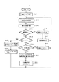
図5は、第1の実施形態における体感警報処理を説明する図である。また、図6は、第1の実施形態においてメインコントローラ1が実行する体感警報処理を示すフローチャートであり、メインコントローラ1に設けられた不図示のマイクロコンピュータが実行する制御プログラムの手順を示す。
【0039】
図6において、ステップS1,ステップS2:レーザレーダ3による検出結果及び/または路車間通信機4によって外部より受信した情報に基づいて、一般的な手法により、車両100(自車両)の前方に存在する障害物(他車両等)に関する情報を取得する(ステップS1)と共に、取得した情報に基づいて、一般的な手法により、当該障害物と車両100との衝突の危険性を判断する(ステップS2)。
【0040】
ステップS3,ステップS6:ステップS2にて算出した衝突に関する危険性に応じて、車両100の自動的な制動を伴う体感警報の発報が必要かを判断し(ステップS3)、この判断で体感警報が必要と判断された場合はステップS4に進み、必要無いと判断された場合には、体感警報の出力は行なわないと決定し(ステップS6)、ステップS1に戻る。
【0041】
ステップS4:ステップS3にて体感警報が必要と判断されたので、今回の制御周期における減速指令値BCとして、減速基準指令値BCBとオフセット値とを加算する。
【0042】
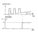
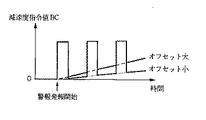
即ち、ステップS4では、図5に示すように、警報発報が必要と判断された最初のタイミング(警報開始タイミング)からの経過時間に応じて矩形波状(パルス状)に変化する減速基準指令値BCBに対して、その警報開始タイミングからの経過時間に応じて漸増するオフセット量(ベース値)を加算することにより、同図の3段目に示す減速指令値BCが、今回の制御周期において実際に出力されるべき指令値として算出される。
【0043】
ステップS5:ステップS4にて算出された減速指令値BCを、ブレーキECU10に設定する。このとき、ブレーキECU10は、設定された減速指令値BCに応じて、ブレーキアクチュエータ11を駆動することによって車両100をドライバの運転操作とは無関係に自動的に減速する。これにより、ドライバは、車両100に発生した人工的な前後方向の挙動により、前方障害物への体感警報であると認知する。
【0044】
このように、本実施形態において、自動的な制動動作によって体感的な警報を行なう際に、車両100に対する制動力は、所定周期で矩形波状に増減する減速基準指令値BCBと、時間の経過に応じて漸増するベース値(オフセット値)との和である減速指令値BCに基づく減速動作態様なので、適切な自動制動を行なうことができると共に、ドライバは、減速指令値BCに応じた自車両の挙動変化により、前方障害物に対する警報であることを容易に認識することができる。
【0045】
[第2の実施形態]
次に、上述した第1の実施形態を基本とする第2の実施形態を説明する。以下の説明においては、第1の実施形態と同様な構成については重複する説明を省略し、本実施形態における特徴的な部分を中心に説明する。
【0046】
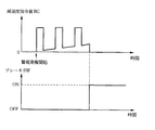
図7は、第2の実施形態における体感警報処理を説明する図である。
【0047】
本実施形態では、図7に示すように、第1の実施形態と同様に障害物に関する体感警報を行なっているときに、ブレーキスイッチ5がオン状態となってドライバによるブレーキ操作が検出された際には、係る体感警報を中止する。具体的な処理としては、上述した図6のステップS4において減速指令値BCを決定するに際して、ブレーキスイッチ5がオン状態であることが検出されている場合には、今回の制御周期における減速指令値BCとしてゼロを設定する。この場合、ブレーキ圧センサ6による検出結果に応じてブレーキECU10がブレーキアクチュエータ11を駆動することにより、車両100は、ドライバの操作に応じて減速する。
【0048】
このような本実施形態によれば、ドライバによるブレーキ操作が行なわれているときには自動的な制動を伴う体感警報が中止されるので、そのブレーキ操作中にも係る体感警報が実行されることによるドライバの違和感を防止することができる。
【0049】
[第3の実施形態]
次に、上述した第1の実施形態を基本とする第3の実施形態を説明する。以下の説明においては、第1の実施形態と同様な構成については重複する説明を省略し、本実施形態における特徴的な部分を中心に説明する。
【0050】
本実施形態では、第1の実施形態と同様に体感警報が行われている場合に、ドライバによるブレーキ操作が検出された際には、減速指令値BCとして、警報開始タイミングからの経過時間に応じて漸増するオフセット量(ベース値)だけを設定することにより、自動制動としての制動力を保持したままの状態で、ドライバによるブレーキ操作に応じた制動を行なう。
【0051】
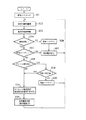
図8は、第3の実施形態においてメインコントローラ1が実行する体感警報処理を示すフローチャートであり、メインコントローラ1に設けられた不図示のマイクロコンピュータが実行する制御プログラムの手順を示す。また、図9は、第3の実施形態における体感警報処理を説明する図である。
【0052】
図8において、ステップS11:内部処理用の解除フラグをゼロにリセットする。
【0053】
ステップS12〜ステップS14:第1の実施形態における図6のステップS1からステップS3と同様な処理を行なうことにより、体感警報の要否を判定する。
【0054】
ステップS15:ステップS14の判断で体感警報が必要と判断された場合は、解除フラグの状態が1にセットされているかを判断し、解除フラグの状態がゼロにセットされている場合にはステップS18に進み、当該解除フラグが1にセットされていると判断された場合には、ステップS22に進む。
【0055】
ステップS16,ステップS17:ステップS14の判断で体感警報が必要無いと判断された場合は、解除フラグの状態をゼロにセットし(ステップS16)、体感警報の出力は行なわないと決定し(ステップS17)、ステップS12に戻る。
【0056】
ステップS18,ステップS19:ブレーキスイッチ5がオン状態となってドライバによるブレーキ操作が検出されたかを判断し(ステップS18)、ブレーキ操作が検出されない場合はステップS20に進み、ブレーキ操作が検出された場合は、解除フラグの状態を1にセットし(ステップS19)、ステップS12に戻る。ステップS19にて解除フラグの状態を1にセットした場合、次の制御周期のステップS27において体感警報が停止される。
【0057】
ステップS20,ステップS21:ステップS16ではドライバによるブレーキ操作が検出されていないので、第1の実施形態における図6のステップS4及びステップS5と同様な処理を行なうことによって体感警報を実行し、ステップS12に戻る。
【0058】
ステップS22:ステップS14の判断結果により警報発報が必要であって、且つステップS15の判断結果により解除フラグが1にセットされているので、ステップS22では、オフセット値を、今回の制御周期における減速度指令値BCとして設定する。ここで、本ステップにて設定されるオフセット値は、図9に示すように、警報開始タイミングからの経過時間に応じて漸増するオフセット量(ベース値)であり、矩形波状の減速度基準指令値BCBは加算されない。
【0059】
ステップS23:ステップS22にて設定された減速度指令値BCを、ブレーキECU10に出力し、ステップS12に戻る。
【0060】
このような本実施形態によれば、ドライバによるブレーキ操作が行なわれているときには、減速指令値BCから矩形波状の減速基準指令値BCBが差し引かれるので、そのブレーキ操作中にも第1の実施形態の如く体感警報が実行されることによるドライバの違和感を防止することができると共に、ドライバによる障害物認識後のブレーキ操作の不足による危険な状態を確実に補うことができる。
【0061】
[第4の実施形態]
次に、上述した第1の実施形態を基本とする第4の実施形態を説明する。以下の説明においては、第1の実施形態と同様な構成については重複する説明を省略し、本実施形態における特徴的な部分を中心に説明する。
【0062】
一般に、急な下り勾配においては、前方に障害物が存在するか否かに関らずに、ドライバはブレーキ操作によって自車両の走行速度の調整を行なう場合が多い。
【0063】
そこで、本実施形態では、車両100が所定勾配より急な下り勾配を走行している際に、第1の実施形態と同様に体感警報が行われている場合には、ドライバによるブレーキ操作を検出しても、体感警報を継続する。
【0064】
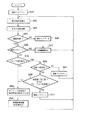
図10は、第4の実施形態における体感警報処理を説明する図である。また、図11は、第4の実施形態においてメインコントローラ1が実行する体感警報処理を示すフローチャートであり、メインコントローラ1に設けられた不図示のマイクロコンピュータが実行する制御プログラムの手順を示す。
【0065】
図11において、ステップS21〜ステップS27:上述した第3の実施形態における図8のステップS11乃至ステップS17と同様な処理を行なう。但し、ステップS25の判断で解除フラグが1である場合に、本ステップではステップS27に進んで体感警報を停止する。
【0066】
ステップS28,ステップS29:上述した第3の実施形態における図8のステップS18と同様な処理によってドライバによるブレーキ操作の有無を検出し(ステップS28)、ブレーキ操作が検出されない場合はステップS31に進み、ドライバによるブレーキ操作が検出された場合には、走行路の勾配が所定勾配より急な下り勾配であるかを判断する(ステップS29)。走行路の勾配は、ナビゲーションユニット7または路車間通信機4を利用して取得すれば良い。
【0067】
そして、ステップS29の判断で急な下り勾配を走行中であることが検出された場合には、ステップS28にてドライバによるブレーキ操作が検出されているものの、そのブレーキ操作は障害物を回避するためではなく、単に下り坂における自車両の速度調整のために行われた可能性があるので、体感警報を継続すべくステップS31に進む。
【0068】
一方、ステップS29の判断で急な下り勾配を走行中ではないことが検出された場合には、ステップS28にて検出されたドライバによるブレーキ操作は障害物を回避するための操作であると判断できるので、体感警報を解除すべく解除フラグを1にセットし、ステップS22に戻る。この場合、次の制御周期のステップS27において体感警報が停止される。
【0069】
ステップS31,ステップS32:上述した第1の実施形態における図6のステップS4乃至ステップS5と同様な処理を行なうことにより、体感警報を実行する。
【0070】
このような本実施形態によれば、所定勾配より急な下り勾配を走行中には、下り坂における自車両の速度調節のため、或いは障害物回避のためにドライバがブレーキ操作を検出した場合であっても障害物に関する体感警報が継続されるので、体感警報が動作していることを、ドライバに対して確実に報知することができる。また、急な下り勾配以外の走行路では、ドライバによるブレーキ操作が検出された場合には障害物に関する体感警報が中止されるので、ドライバの違和感を防止することができる。
【0071】
<第4の実施形態の変形例>
上述した第4の実施形態では、前方障害物に関する体感警報が動作していることをドライバに対して確実に報知することを目的として、急な下り勾配を走行中には、ドライバによるブレーキ操作が検出された場合であっても障害物に関する体感警報を継続した。
【0072】
ここで、障害物を回避するためのブレーキ操作は下り坂における速度調節のためのブレーキ操作の場合と比較して一般的に大きさ操作力(踏力)である。そこで、本変形例では、所定勾配より急な下り勾配を走行中にドライバによるブレーキ操作が検出された場合に、そのブレーキ操作が所定の強さより大きい場合には、体感警報を中止する。
【0073】
図12は、第4の実施形態の変形例においてメインコントローラ1が実行する体感警報処理を示すフローチャートであり、メインコントローラ1に設けられた不図示のマイクロコンピュータが実行する制御プログラムの手順を示す。
【0074】
図12において、ステップS41〜ステップS49,ステップS52:上述した第4の実施形態における図11のステップS21乃至ステップS29、並びにステップS30と同様な処理を行なう。
【0075】
ステップS50,ステップS51:ドライバによるブレーキ操作力を、ブレーキ圧センサ6による検出結果から求め、そのブレーキ操作力が所定値より大きいかを判断する(ステップS50)。或いは、ステップS50では、前後Gセンサ2の検出結果に基づいて検出した減速度が所定値より大きいかを判断する。そして、ドライバによるブレーキ操作力が所定値以下の場合には、体感警報を継続すべくステップS53に進み、ドライバによるブレーキ操作力が所定値より大きい場合には、ステップS51において解除フラグを1にセットし、ステップS42に戻る。
【0076】
ステップS53,ステップS54:上述した第4の実施形態における図11のステップS31乃至ステップS32と同様な処理を行なうことにより、体感警報を実行する。
【0077】
このように本変形例では、障害物に関する体感警報を行なっているときに、自車両が所定勾配より急な下り勾配を走行していることが検出された際には、ドライバによる所定の強さより大きなブレーキ操作が検出されない限り、体感警報が継続される。これにより、体感警報が動作していることをドライバに対して確実に報知することができると共に、そのブレーキ操作中にも係る障害物警報が実行されることによるドライバの違和感を防止することができる。
【0078】
[第5の実施形態]
次に、上述した第1の実施形態を基本とする第5の実施形態を説明する。以下の説明においては、第1の実施形態と同様な構成については重複する説明を省略し、本実施形態における特徴的な部分を中心に説明する。
【0079】
本実施形態では、上述した第1の実施形態における図6のステップS4において減速度指令値BCを決定するに際して、ベース値(オフセット値)の大きさを、図13に示すように、車両の状態に応じて適宜変更する。このとき、大きなオフセット値が設定される場合には、小さなオフセット値が設定される場合と比較して、体感警報が実行される期間における平均値として、大きな値の減速度指令値BCがブレーキECU10に設定されるので、車両100の自動的な制動動作がより積極的に行われることになる。
【0080】
また、ベース値の変更に際して参照する車両の状態としては、障害物と自車両との距離に関する値、車両の運転状態を表わすパラメータ、車両周囲の走行路環境を表わすパラメータの少なくとも何れかに応じて変更すれば良い。次に、係る車両の状態に応じてベース値を変更する場合の具体例について説明する。
【0081】
本実施形態では、上述した第1の実施形態における図6のステップS4において減速度指令値BCを決定するに際して、ベース値(オフセット値)の大きさを、大別して、障害物との衝突危険度に関するパラメータ、ドライバの前方視認性の度合に関するパラメータ、そして車両の走行安定性に関するパラメータの優先順位で変更する。
【0082】
図14は、第5の実施形態におけるベース値の優先順位を示す設定テーブルであり、予めメインコントローラ1の不図示のメモリ等に記憶されている。この設定テーブルは、図6のステップS4において減速度指令値BCを決定するに際して、採用すべきベース値(オフセット値)を決定するために参照される。より具体的には、優先順位の高い条件が成立するほど、ベース値として大きな値が設定されるように補正すると共に、その際、複数項目の条件が成立する場合には、予め設定した優先順位の高い方のパラメータに基づくベース値を採用する。
【0083】
図14において、優先順位1乃至4は、障害物との衝突危険度に関するパラメータであり、優先順位5乃至6は、ドライバの前方視認性の度合に関するパラメータであり、優先順位7は、車両の走行安定性に関するパラメータである。
【0084】
より具体的に、優先順位1が一番高い「障害物までの距離」は、レーザレーダ3または路車間通信機4によって取得可能な情報項目であり、取得した障害物までの距離が所定値(所定距離)L0以下の場合には条件成立と判断する。ここで、障害物までの距離が優先順位1である理由は、他の状態と比較して最も緊急性、緊迫性が高いからである。
【0085】
次に、優先順位2の「車速」は、車速センサ(不図示)によって取得可能な情報項目であり、取得した車速が所定値V0以上の場合には条件成立と判断する。ここで、車速が優先順位2である理由は、障害物までの距離に準じて衝突の危険度が高いからである。
【0086】
次に、優先順位3の「加減速度」は、前後Gセンサ2や車速センサ(不図示)の検出結果に基づく計算によって取得可能な情報項目であり、取得した加速度が所定値A0以上の場合には条件成立と判断する。ここで、加減速度が優先順位3である理由は、障害物までの距離、車速に準じて衝突の危険度が高いからである。
【0087】
次に、優先順位4の「道路の縦勾配」は、ナビゲーションユニット7または路車間通信機4によって取得可能な情報項目であり、取得した勾配が下り勾配であってその勾配の度合いが所定量(%)以上の場合には条件成立と判断する。ここで、道路の縦勾配が優先順位4である理由は、障害物までの距離、車速、加減速度よりは優先順位を低く設定できるものの、道路の傾きにより、障害物までの距離変化が大きく変化するので危険度が高いからである。
【0088】
次に、優先順位5の「カーブの曲率」は、ナビゲーションユニット7または路車間通信機4によって取得可能な情報項目であり、取得した曲率が所定値r0以上の場合には条件成立と判断する。ここで、カーブの曲率が優先順位5である理由は、上述した優先順位1乃至4の障害物との衝突危険度に関するパラメータよりは優先順位を低く設定できるものの、前方にブラインドカーブとなっている道路が存在する場合は、そのブラインドカーブのカーブがきついほど危険度が高いからである。
【0089】
次に、優先順位6の「照度」は、例えばヘッドライトスイッチ9の操作状態によって取得可能な情報項目であり、所定照度S0以下である走行路周囲が暗い夜間(ヘッドライトスイッチ9はオン状態)の場合には条件成立と判断する。ここで、照度が優先順位6である理由は、上述した優先順位1乃至4の障害物との衝突危険度に関するパラメータよりは優先順位を低く設定できるものの、走行路の視認性が大きく変化するので危険度が高いからである。
【0090】
そして、優先順位7の「路面状態」は、路車間通信機4によって取得可能な情報項目であり、取得した摩擦係数μが所定値μ0以上の場合には条件成立と判断する。ここで、路面状態が優先順位7である理由は、上述した他のパラメータよりは優先順位を低く設定できるものの、車両の安定性を維持するためにはオフセット量を変更すべきだからである。
【0091】
このような本実施形態によれば、体感警報が行われる際に、自動的な制動動作の度合いを、危険性に応じて適切に調整することができる。
【図面の簡単な説明】
【図1】第1の実施形態における前方障害物への衝突防止支援システムの動作を説明する図である。
【図2】第1の実施形態における前方障害物への衝突防止支援システムによって車両上で報知される警報の態様を説明する図である。
【図3】第1の実施形態における車両100に搭載される主な機器の配置を例示する図である。
【図4】第1の実施形態における車両100の制御系の構成を示すブロック図である。
【図5】第1の実施形態における体感警報処理を説明する図である。
【図6】第1の実施形態においてメインコントローラ1が実行する体感警報処理を示すフローチャートである。
【図7】第2の実施形態における体感警報処理を説明する図である。
【図8】第3の実施形態においてメインコントローラ1が実行する体感警報処理を示すフローチャートである。
【図9】第3の実施形態における体感警報処理を説明する図である。
【図10】第4の実施形態における体感警報処理を説明する図である。
【図11】第4の実施形態においてメインコントローラ1が実行する体感警報処理を示すフローチャートである。
【図12】第4の実施形態の変形例においてメインコントローラ1が実行する体感警報処理を示すフローチャートである。
【図13】第5の実施形態における体感警報処理においてオフセット値を変更することを説明する図である。
【図14】第5の実施形態におけるベース値の優先順位を示す設定テーブルである。
【符号の説明】
1:メインコントローラ,
2:前後Gセンサ,
3:レーザレーダ,
4:路車間通信機,
5:ブレーキスイッチ,
6:ブレーキ圧センサ,
7:ナビゲーションユニット,
8:GPSユニット,
9:ヘッドライトスイッチ,
10:ブレーキECU,
11:ブレーキアクチュエータ,
12:ディスプレイ,
13:スピーカ,
15:路車間通信機アンテナ,
100:車両,
200:障害物センサ,
300:路車間通信設備,[0001]
BACKGROUND OF THE INVENTION
The present invention relates to the field of alarm devices that generate alarms related to obstacles existing in front of a host vehicle.
[0002]
[Prior art]
Conventionally, in the field of automobiles, which are typical vehicles, various warning devices have been proposed that issue warnings about obstacles existing ahead to the driver.
[0003]
As an example of such an alarm device, for example, in JP-A-11-189071, lane departure prevention control and inter-vehicle distance control with another vehicle traveling ahead are performed, and the state of these controls is set in the vehicle. A forward obstacle warning system has been proposed to display appropriately.
[0004]
[Problems to be solved by the invention]
According to the above conventional technique, it is possible to prevent lane departure and maintain a safe inter-vehicle distance. However, since alarm operations are performed for a plurality of events, those alarms are issued. When this happens, the driver may not be able to instantaneously determine which alarm is being issued.
[0005]
In such a vehicle alarm system, the traveling vehicle automatically brakes independently of the driving operation by the driver, so the driver often feels uncomfortable.
[0006]
SUMMARY OF THE INVENTION Accordingly, an object of the present invention is to provide a vehicle control device that gives an alarm about an obstacle existing ahead of the host vehicle and performs appropriate automatic braking in an operation mode that can be easily recognized by a driver.
[0007]
[Means for Solving the Problems]
In order to achieve the above object, a vehicle control apparatus according to the present invention is characterized by the following configuration.
[0008]
That is, the obstacle detection means for detecting a value related to the distance between the obstacle existing in front and the vehicle, and the braking control for automatically braking the traveling speed of the vehicle independently of the driving operation by the driver of the vehicle And when the value relating to the distance satisfies a predetermined condition, the braking force applied to the vehicle by the braking control means is adjusted so as to increase or decrease in a predetermined cycle, and the base value of the braking force is set as time elapses. It is characterized by comprising alarm means for performing an obstacle alarm for the driver by changing so as to increase gradually.
[0009]
In a preferred embodiment, the alarm means may stop the obstacle alarm when detecting a brake operation by the driver while performing the obstacle alarm.
[0010]
Further, for example, the alarm means detects a brake operation by the driver when detecting that the vehicle is traveling on a downward slope that is steeper than a predetermined slope while the obstacle alarm is being performed. However, the obstacle alarm may be continued.
[0011]
Alternatively, when the alarm means detects that the vehicle is traveling on a downward slope that is steeper than a predetermined slope while performing the obstacle alarm, the brake means applies a brake larger than a predetermined strength by the driver. As long as no operation is detected, the obstacle alarm may be continued.
[0012]
Further, in another preferred embodiment, the braking control means, as an adjustment result by the warning means, detects a brake operation by the driver when an obstacle warning is given by the warning means. It is preferable to perform braking according to the brake operation by the driver while maintaining the braking force of the driver.
[0013]
Further, for example, the alarm means may include at least one of a magnitude of the base value, a value related to a distance between the obstacle and the vehicle, a parameter representing the driving state of the vehicle, and a parameter representing a traveling road environment around the vehicle. It is good to change it according to your needs.
[0014]
In this case, the warning means determines the magnitude of the base value, a parameter relating to the collision risk with the obstacle, a parameter relating to the degree of forward visibility of the driver, and a parameter priority relating to the driving stability of the vehicle. It is good to change with.
[0015]
【The invention's effect】
According to the present invention described above, it is possible to provide a vehicle control device that performs an alarm regarding an obstacle existing ahead of the host vehicle and performs appropriate automatic braking in an operation mode that can be easily recognized by the driver.
[0016]
That is, according to the first aspect of the present invention, when a sensible alarm is given by an automatic braking operation, the braking force increases or decreases in a predetermined cycle, and the base value of the braking force gradually increases as time elapses. Therefore, it is possible to perform appropriate automatic braking, and the driver can easily recognize that it is an alarm for a front obstacle.
[0017]
According to the invention of
[0018]
In general, on a steep downhill slope, the driver often adjusts the traveling speed by a brake operation regardless of whether there is an obstacle ahead of the vehicle. For example, while driving on a steep downhill slope, the obstacle alarm will continue even if a brake operation by the driver is detected, so the driver can be sure that the obstacle alarm is operating. Can be notified.
[0019]
Further, in the steep downward slope in which the driver adjusts the traveling speed by the brake operation as described above, the brake operation by the driver is not so strong (for example, a pedaling force against the brake pedal). For example, the obstacle alarm is continued unless a brake operation greater than a predetermined strength by the driver is detected. That is, when the driver recognizes an obstacle existing ahead and performs a braking operation with great strength, the obstacle alarm is stopped. Accordingly, it is possible to reliably notify the driver that the obstacle alarm is operating, and to prevent the driver from feeling uncomfortable due to the obstacle alarm being executed even during the brake operation. it can.
[0020]
Further, according to the invention of
[0021]
According to the invention of
[0022]
According to the invention of
[0023]
DETAILED DESCRIPTION OF THE INVENTION
DESCRIPTION OF EMBODIMENTS Hereinafter, a vehicle control apparatus according to the present invention will be described in detail with reference to the drawings as an embodiment in which the vehicle control apparatus is applied to a collision prevention support system for a front obstacle.
[0024]
[First Embodiment]
In the present embodiment, the collision prevention support system generates a warning by display and sound (sound) in the own vehicle to prevent a collision with an obstacle existing in front of the own vehicle, and automatically as described later. By performing proper braking, an alarm (sensation alarm) that the driver can experience is performed. In the present embodiment, the bodily sensation alarm means that when the vehicle being driven by the driver decelerates by an automatic braking operation in a predetermined braking mode, the driver changes the behavior of the own vehicle when the vehicle is decelerated. It is an alarm that can be recognized by a bodily sensation that the danger of a collision related to an obstacle existing in front of is notified.
[0025]
First, prior to describing characteristic sensation alarm control according to the present embodiment, the basic operation of the collision prevention support system will be described.
[0026]
FIG. 1 is a diagram for explaining the operation of the collision prevention support system for a front obstacle in the first embodiment. Moreover, FIG. 2 is a figure explaining the aspect of the alarm alert | reported on a vehicle by the collision prevention assistance system to the front obstacle in 1st Embodiment.
[0027]
In the present embodiment, as a predetermined facility (so-called infrastructure) provided on the road side in the traveling path of the
[0028]
When there is an obstacle ahead, the control device of the vehicle 100 (corresponding to a main controller 1 described later) acquires the distance between the obstacle and the host vehicle from the road-to-vehicle communication facility 300 or the
[0029]
And the control apparatus of the
First, when there is a relatively large distance to the obstacle, as shown in FIG. 2A, information providing for notifying the presence of the obstacle is displayed (corresponding to the
-Next, if there is no allowance for the distance to the obstacle, as shown in FIG.
-And if braking is necessary immediately to avoid a collision with an obstacle, as shown in FIG. 2 (c), this is indicated by a display on the display and an alarm sound. As an alarm, automatic braking of the
[0030]
Next, equipment mounted on the
[0031]
FIG. 3 is a diagram illustrating an arrangement of main devices mounted on the
[0032]
3 and 4, the longitudinal acceleration (G)
[0033]
The
[0034]
In addition, the
[0035]
The main controller 1 performs braking control of the
[0036]
Further, the main controller 1 performs screen display on the
[0037]
Of the alarm control processing executed by the main controller 1 in the present embodiment, alarm processing (including providing information related to the front of the vehicle) by screen display on the
[0038]
FIG. 5 is a diagram for explaining the sensation alarm processing according to the first embodiment. FIG. 6 is a flowchart showing a bodily sensation alarm process executed by the main controller 1 in the first embodiment, and shows a procedure of a control program executed by a microcomputer (not shown) provided in the main controller 1.
[0039]
In FIG. 6, Step S1, Step S2: Presence in front of the vehicle 100 (own vehicle) by a general method based on the detection result by the
[0040]
Step S3, Step S6: It is determined whether it is necessary to issue a bodily sensation alarm accompanied by automatic braking of the
[0041]
Step S4: Since it is determined in step S3 that a sensation alarm is necessary, the deceleration reference command value BCB and the offset value are added as the deceleration command value BC in the current control cycle.
[0042]
That is, in step S4, as shown in FIG. 5, a deceleration reference command value that changes in a rectangular wave shape (pulse shape) in accordance with the elapsed time from the first timing (warning start timing) at which it is determined that warning is required By adding an offset amount (base value) that gradually increases according to the elapsed time from the alarm start timing to the BCB, the deceleration command value BC shown in the third stage of FIG. Is calculated as a command value to be output to
[0043]
Step S5: The deceleration command value BC calculated in step S4 is set in the
[0044]
As described above, in the present embodiment, when a sensible alarm is given by an automatic braking operation, the braking force applied to the
[0045]
[Second Embodiment]
Next, a second embodiment based on the above-described first embodiment will be described. In the following description, the description similar to that of the first embodiment will be omitted, and the description will focus on the characteristic part of the present embodiment.
[0046]
FIG. 7 is a diagram for explaining the sensation alarm processing in the second embodiment.
[0047]
In the present embodiment, as shown in FIG. 7, when the sensation alarm regarding the obstacle is performed as in the first embodiment, the
[0048]
According to the present embodiment as described above, when the brake operation is performed by the driver, the sensation alarm accompanied by automatic braking is stopped, so that the sensation alarm is executed even during the brake operation. Can prevent a sense of incongruity.
[0049]
[Third Embodiment]
Next, a third embodiment based on the above-described first embodiment will be described. In the following description, the description similar to that of the first embodiment will be omitted, and the description will focus on the characteristic part of the present embodiment.
[0050]
In the present embodiment, in the same way as in the first embodiment, when the brake operation by the driver is detected, the deceleration command value BC is used as the deceleration command value BC according to the elapsed time from the alarm start timing. By setting only the offset amount (base value) that gradually increases, braking according to the brake operation by the driver is performed while maintaining the braking force as automatic braking.
[0051]
FIG. 8 is a flowchart showing a bodily sensation alarm process executed by the main controller 1 in the third embodiment, and shows a procedure of a control program executed by a microcomputer (not shown) provided in the main controller 1. FIG. 9 is a diagram for explaining the sensation alarm processing in the third embodiment.
[0052]
In FIG. 8, step S11: reset the internal processing release flag to zero.
[0053]
Step S12 to Step S14: The necessity of the sensation alarm is determined by performing the same processing as Step S1 to Step S3 of FIG. 6 in the first embodiment.
[0054]
Step S15: If it is determined in step S14 that a sensation alarm is necessary, it is determined whether the release flag is set to 1. If the release flag is set to zero, step S18 is executed. If it is determined that the release flag is set to 1, the process proceeds to step S22.
[0055]
Steps S16 and S17: If it is determined in step S14 that no sensation alarm is necessary, the state of the release flag is set to zero (step S16), and it is determined that no sensation alarm is output (step S17). ), The process returns to step S12.
[0056]
Steps S18 and S19: It is determined whether the
[0057]
Step S20, Step S21: Since the brake operation by the driver is not detected in Step S16, a sensation alarm is executed by performing the same processing as Step S4 and Step S5 of FIG. 6 in the first embodiment, and Step S12. Return to.
[0058]
Step S22: An alarm is required based on the determination result in Step S14, and the release flag is set to 1 based on the determination result in Step S15. Therefore, in Step S22, the offset value is decreased in the current control cycle. Set as speed command value BC. Here, as shown in FIG. 9, the offset value set in this step is an offset amount (base value) that gradually increases in accordance with the elapsed time from the alarm start timing, and is a rectangular wave-shaped deceleration reference command value. BCB is not added.
[0059]
Step S23: The deceleration command value BC set in step S22 is output to the
[0060]
According to the present embodiment as described above, when the brake operation by the driver is performed, the rectangular wave-shaped deceleration reference command value BCB is subtracted from the deceleration command value BC. Therefore, the first embodiment is also performed during the brake operation. As described above, it is possible to prevent the driver from feeling uncomfortable due to the sensation alarm being executed, and to reliably compensate for a dangerous state due to insufficient braking operation after obstacle recognition by the driver.
[0061]
[Fourth Embodiment]
Next, a fourth embodiment based on the first embodiment described above will be described. In the following description, the description similar to that of the first embodiment will be omitted, and the description will focus on the characteristic part of the present embodiment.
[0062]
In general, on a steep downhill slope, the driver often adjusts the traveling speed of the host vehicle by a brake operation regardless of whether there is an obstacle ahead.
[0063]
Therefore, in the present embodiment, when the
[0064]
FIG. 10 is a diagram illustrating the bodily sensation alarm process according to the fourth embodiment. FIG. 11 is a flowchart showing a bodily sensation alarm process executed by the main controller 1 in the fourth embodiment, and shows a procedure of a control program executed by a microcomputer (not shown) provided in the main controller 1.
[0065]
In FIG. 11, Steps S21 to S27: Processing similar to Steps S11 to S17 of FIG. 8 in the third embodiment described above is performed. However, if the release flag is 1 in the determination in step S25, the process proceeds to step S27 in this step to stop the sensation alarm.
[0066]
Step S28, Step S29: The presence or absence of a brake operation by the driver is detected by the same process as Step S18 of FIG. 8 in the third embodiment described above (Step S28). If no brake operation is detected, the process proceeds to Step S31. If a brake operation by the driver is detected, it is determined whether the gradient of the traveling road is a downward gradient that is steeper than a predetermined gradient (step S29). The gradient of the travel path may be acquired using the
[0067]
If it is detected in step S29 that the vehicle is traveling on a steep downhill slope, a brake operation by the driver is detected in step S28, but the brake operation avoids an obstacle. Instead, there is a possibility that it was simply performed for adjusting the speed of the vehicle on the downhill, and therefore the process proceeds to step S31 in order to continue the sensation alarm.
[0068]
On the other hand, when it is detected in step S29 that the vehicle is not traveling on a steep downward slope, it can be determined that the brake operation by the driver detected in step S28 is an operation for avoiding an obstacle. Therefore, the release flag is set to 1 to release the bodily sensation alarm, and the process returns to step S22. In this case, the sensation alarm is stopped in step S27 of the next control cycle.
[0069]
Step S31, Step S32: A bodily sensation alarm is executed by performing the same processing as Step S4 to Step S5 of FIG. 6 in the first embodiment described above.
[0070]
According to this embodiment as described above, when the vehicle detects a braking operation for traveling on a downward slope that is steeper than a predetermined slope, for adjusting the speed of the vehicle on a downward slope or for avoiding an obstacle. Even if it exists, since the bodily sensation alarm is continued, it can be surely notified to the driver that the bodily sensation alarm is operating. Further, on a road other than a steep downward slope, when a brake operation by the driver is detected, the sensation alarm regarding the obstacle is stopped, so that it is possible to prevent the driver from feeling uncomfortable.
[0071]
<Modification of Fourth Embodiment>
In the above-described fourth embodiment, the brake operation by the driver is performed while driving on a steep downhill for the purpose of surely informing the driver that the sensation alarm regarding the front obstacle is operating. Even if it was detected, the sensible alarm regarding the obstacle was continued.
[0072]
Here, the brake operation for avoiding the obstacle is generally a magnitude operation force (stepping force) as compared with the brake operation for speed adjustment on the downhill. Therefore, in this modification, when a brake operation by the driver is detected while traveling on a downward slope that is steeper than a predetermined gradient, if the brake operation is greater than a predetermined strength, the sensation alarm is stopped.
[0073]
FIG. 12 is a flowchart showing a sensation alarm process executed by the main controller 1 in the modification of the fourth embodiment, and shows a procedure of a control program executed by a microcomputer (not shown) provided in the main controller 1.
[0074]
In FIG. 12, Steps S41 to S49, Step S52: Processing similar to Steps S21 to S29 and Step S30 of FIG. 11 in the fourth embodiment described above is performed.
[0075]
Step S50, Step S51: The brake operation force by the driver is obtained from the detection result by the
[0076]
Step S53, Step S54: A bodily sensation alarm is executed by performing the same processing as Step S31 to Step S32 of FIG. 11 in the fourth embodiment described above.
[0077]
As described above, in the present modification, when it is detected that the host vehicle is traveling on a downward slope that is steeper than the predetermined slope when the sensation alarm regarding the obstacle is performed, the predetermined strength by the driver is used. Unless a large brake operation is detected, the sensation alarm is continued. As a result, it is possible to reliably notify the driver that the bodily sensation alarm is operating, and to prevent the driver from feeling uncomfortable due to the obstacle alarm being executed even during the brake operation. .
[0078]
[Fifth Embodiment]
Next, a fifth embodiment based on the first embodiment described above will be described. In the following description, the description similar to that of the first embodiment will be omitted, and the description will focus on the characteristic part of the present embodiment.
[0079]
In this embodiment, when the deceleration command value BC is determined in step S4 of FIG. 6 in the first embodiment described above, the magnitude of the base value (offset value) is set to the vehicle state as shown in FIG. Change accordingly. At this time, when a large offset value is set, as compared with a case where a small offset value is set, a large deceleration command value BC is set as an average value during the period in which the sensation alarm is executed. Therefore, the automatic braking operation of the
[0080]
The vehicle state referred to when the base value is changed depends on at least one of a value related to the distance between the obstacle and the host vehicle, a parameter indicating the driving state of the vehicle, and a parameter indicating the traveling road environment around the vehicle. Change it. Next, a specific example of changing the base value according to the state of the vehicle will be described.
[0081]
In the present embodiment, when determining the deceleration command value BC in step S4 of FIG. 6 in the first embodiment described above, the base value (offset value) is roughly classified and the risk of collision with an obstacle is roughly divided. , Parameters relating to the degree of forward visibility of the driver, and parameters relating to the driving stability of the vehicle.
[0082]
FIG. 14 is a setting table showing the priority order of base values in the fifth embodiment, and is stored in advance in a memory (not shown) of the main controller 1. This setting table is referred to in order to determine a base value (offset value) to be adopted when determining the deceleration command value BC in step S4 of FIG. More specifically, correction is performed so that a larger value is set as the base value as the higher priority condition is satisfied, and at that time, when a plurality of conditions are satisfied, a preset priority order is set. The base value based on the higher parameter is adopted.
[0083]
In FIG. 14, priorities 1 to 4 are parameters relating to the risk of collision with an obstacle,
[0084]
More specifically, the “distance to an obstacle” having the highest priority 1 is an information item that can be acquired by the
[0085]
Next, “vehicle speed” of
[0086]
Next, “acceleration / deceleration” of
[0087]
Next, “Road vertical gradient” of
[0088]
Next, the “curvature curvature” of
[0089]
Next, “illuminance” of
[0090]
The “road surface state” of the
[0091]
According to this embodiment, when a sensation alarm is performed, the degree of automatic braking operation can be appropriately adjusted according to the risk.
[Brief description of the drawings]
FIG. 1 is a diagram for explaining the operation of a collision prevention support system for a front obstacle in the first embodiment.
FIG. 2 is a diagram illustrating an alarm mode notified on a vehicle by a collision prevention support system for a front obstacle in the first embodiment.
FIG. 3 is a diagram illustrating an arrangement of main devices mounted on the
FIG. 4 is a block diagram showing a configuration of a control system of the
FIG. 5 is a diagram illustrating a bodily sensation alarm process according to the first embodiment.
FIG. 6 is a flowchart showing a bodily sensation alarm process executed by the main controller 1 in the first embodiment.
FIG. 7 is a diagram illustrating a bodily sensation alarm process according to the second embodiment.
FIG. 8 is a flowchart showing a bodily sensation alarm process executed by the main controller 1 in the third embodiment.
FIG. 9 is a diagram for explaining a bodily sensation alarm process according to the third embodiment.
FIG. 10 is a diagram illustrating a bodily sensation alarm process according to the fourth embodiment.
FIG. 11 is a flowchart showing a bodily sensation alarm process executed by the main controller 1 in the fourth embodiment.
FIG. 12 is a flowchart showing a bodily sensation alarm process executed by the main controller 1 in a modification of the fourth embodiment.
FIG. 13 is a diagram for explaining changing an offset value in the bodily sensation alarm processing according to the fifth embodiment.
FIG. 14 is a setting table showing the priority order of base values in the fifth embodiment.
[Explanation of symbols]
1: Main controller,
2: Front / rear G sensor,
3: Laser radar,
4: Road-to-vehicle communication device,
5: Brake switch,
6: Brake pressure sensor,
7: Navigation unit,
8: GPS unit,
9: Headlight switch,
10: Brake ECU,
11: Brake actuator,
12: Display,
13: Speaker,
15: Road-to-vehicle communication device antenna,
100: vehicle,
200: Obstacle sensor,
300: Road-to-vehicle communication equipment,
Claims (7)
前記車両のドライバによる運転操作とは独立して、前記車両の走行速度を自動的に制動する制動制御手段と、
前記距離に関する値が所定の条件を満たす際に、前記制動制御手段による前記車両に対する制動力が所定周期で増減するように調整すると共に、その制動力のベース値を、時間の経過に応じて漸増するように変更することにより、前記ドライバに対する障害物警報を行なう警報手段と、
を備えることを特徴とする車両用制御装置。Obstacle detection means for detecting a value related to the distance between the obstacle present ahead and the vehicle;
A braking control means for automatically braking the traveling speed of the vehicle independently of the driving operation by the driver of the vehicle;
When the value related to the distance satisfies a predetermined condition, the braking force applied to the vehicle by the braking control means is adjusted so as to increase or decrease in a predetermined cycle, and the base value of the braking force is gradually increased as time passes. An alarm means for performing an obstacle alarm for the driver by changing to
A vehicle control device comprising:
前記障害物警報を行なっているときに前記ドライバによるブレーキ操作を検出した際には、前記障害物警報を中止する
ことを特徴とする請求項1記載の車両用制御装置。The alarm means includes
The vehicle control device according to claim 1, wherein when the brake operation by the driver is detected while performing the obstacle alarm, the obstacle alarm is stopped.
前記障害物警報を行なっているときに、前記車両が所定勾配より急な下り勾配を走行していることを検出した際には、前記ドライバによるブレーキ操作を検出しても、前記障害物警報を継続する
ことを特徴とする請求項1または請求項2記載の車両用制御装置。The alarm means includes
When it is detected that the vehicle is traveling on a downward slope that is steeper than a predetermined slope when the obstacle alarm is being performed, the obstacle alarm is not detected even if a brake operation by the driver is detected. 3. The vehicle control device according to claim 1, wherein the control device is continued.
前記障害物警報を行なっているときに、前記車両が所定勾配より急な下り勾配を走行していることを検出した際には、前記ドライバによる所定の強さより大きなブレーキ操作が検出されない限り、前記障害物警報を継続する
ことを特徴とする請求項1または請求項2記載の車両用制御装置。The alarm means includes
When it is detected that the vehicle is traveling on a downward slope that is steeper than a predetermined slope when the obstacle alarm is being performed, unless a braking operation greater than a predetermined strength by the driver is detected, the vehicle The vehicle control device according to claim 1 or 2, wherein the obstacle alarm is continued.
前記警報手段による障害物警報が行われている場合に、前記ドライバによるブレーキ操作を検出した際には、前記警報手段による調整結果としての制動力を保持したままの状態で、前記ドライバによるブレーキ操作に応じた制動を行なう
ことを特徴とする請求項1記載の車両用制御装置。The braking control means includes
When an obstacle alarm is issued by the alarm means, when a brake operation by the driver is detected, the brake operation by the driver is maintained while maintaining the braking force as an adjustment result by the alarm means. The vehicle control device according to claim 1, wherein braking according to the vehicle is performed.
前記ベース値の大きさを、前記障害物と前記車両との距離に関する値、前記車両の運転状態を表わすパラメータ、前記車両周囲の走行路環境を表わすパラメータの少なくとも何れかに応じて変更する
ことを特徴とする請求項1記載の車両用制御装置。The alarm means includes
The magnitude of the base value is changed according to at least one of a value related to a distance between the obstacle and the vehicle, a parameter representing the driving state of the vehicle, and a parameter representing a traveling road environment around the vehicle. The vehicle control device according to claim 1, characterized in that:
前記ベース値の大きさを、前記障害物との衝突危険度に関するパラメータ、前記ドライバの前方視認性の度合に関するパラメータ、そして前記車両の走行安定性に関するパラメータの優先順位で変更する
ことを特徴とする請求項6記載の車両用制御装置。The alarm means includes
The magnitude of the base value is changed according to a priority order of a parameter relating to a collision risk with the obstacle, a parameter relating to the degree of forward visibility of the driver, and a parameter relating to running stability of the vehicle. The vehicle control device according to claim 6.
Priority Applications (1)
| Application Number | Priority Date | Filing Date | Title |
|---|---|---|---|
| JP2001160966A JP4635226B2 (en) | 2001-05-29 | 2001-05-29 | Vehicle control device |
Applications Claiming Priority (1)
| Application Number | Priority Date | Filing Date | Title |
|---|---|---|---|
| JP2001160966A JP4635226B2 (en) | 2001-05-29 | 2001-05-29 | Vehicle control device |
Publications (2)
| Publication Number | Publication Date |
|---|---|
| JP2002347546A JP2002347546A (en) | 2002-12-04 |
| JP4635226B2 true JP4635226B2 (en) | 2011-02-23 |
Family
ID=19004309
Family Applications (1)
| Application Number | Title | Priority Date | Filing Date |
|---|---|---|---|
| JP2001160966A Expired - Fee Related JP4635226B2 (en) | 2001-05-29 | 2001-05-29 | Vehicle control device |
Country Status (1)
| Country | Link |
|---|---|
| JP (1) | JP4635226B2 (en) |
Families Citing this family (12)
| Publication number | Priority date | Publication date | Assignee | Title |
|---|---|---|---|---|
| JP2004255928A (en) | 2003-02-24 | 2004-09-16 | Denso Corp | Vehicle control device |
| JP4706641B2 (en) * | 2003-06-10 | 2011-06-22 | 日産自動車株式会社 | VEHICLE DRIVE OPERATION ASSISTANCE DEVICE AND VEHICLE WITH VEHICLE DRIVE OPERATION ASSISTANCE DEVICE |
| JP2005297945A (en) * | 2004-03-18 | 2005-10-27 | Advics:Kk | Apparatus and method for controlling vehicular brake |
| JP4604683B2 (en) * | 2004-11-25 | 2011-01-05 | 日産自動車株式会社 | Hazardous situation warning device |
| JP2006205773A (en) * | 2005-01-25 | 2006-08-10 | Fujitsu Ten Ltd | Driving supporting device |
| JP4862516B2 (en) * | 2006-06-26 | 2012-01-25 | トヨタ自動車株式会社 | Vehicle deceleration control device |
| JP5900183B2 (en) * | 2012-06-22 | 2016-04-06 | トヨタ自動車株式会社 | Brake control device |
| WO2014155884A1 (en) * | 2013-03-25 | 2014-10-02 | エイディシーテクノロジー株式会社 | Vehicle |
| JP2016162416A (en) * | 2015-03-05 | 2016-09-05 | 株式会社デンソー | Driving support device and driving support method |
| JP6697702B2 (en) | 2015-09-10 | 2020-05-27 | パナソニックIpマネジメント株式会社 | Automatic stop device and automatic stop method |
| JP2017206040A (en) * | 2016-05-16 | 2017-11-24 | トヨタ自動車株式会社 | Vehicular drive support control apparatus |
| JP7529526B2 (en) * | 2020-10-14 | 2024-08-06 | トヨタ自動車株式会社 | Vehicle control device and vehicle control method |
Family Cites Families (8)
| Publication number | Priority date | Publication date | Assignee | Title |
|---|---|---|---|---|
| JPS5554600Y2 (en) * | 1975-03-14 | 1980-12-17 | ||
| JPS5296033U (en) * | 1976-01-14 | 1977-07-18 | ||
| JPS5440432A (en) * | 1977-09-07 | 1979-03-29 | Nissan Motor Co Ltd | Apparatus for preventing collision of vehicle |
| JPH0572629U (en) * | 1992-01-13 | 1993-10-05 | 株式会社曙ブレーキ中央技術研究所 | Automatic braking device |
| JP3201092B2 (en) * | 1993-09-02 | 2001-08-20 | トヨタ自動車株式会社 | Automatic brake device |
| JP3557890B2 (en) * | 1998-03-03 | 2004-08-25 | 三菱ふそうトラック・バス株式会社 | Inter-vehicle distance control device |
| JP3714116B2 (en) * | 1999-08-09 | 2005-11-09 | トヨタ自動車株式会社 | Steering stability control device |
| JP3572448B2 (en) * | 1999-11-11 | 2004-10-06 | 日産自動車株式会社 | Brake control device for vehicle |
-
2001
- 2001-05-29 JP JP2001160966A patent/JP4635226B2/en not_active Expired - Fee Related
Also Published As
| Publication number | Publication date |
|---|---|
| JP2002347546A (en) | 2002-12-04 |
Similar Documents
| Publication | Publication Date | Title |
|---|---|---|
| JP5987906B2 (en) | Driving assistance device | |
| JP6677822B2 (en) | Vehicle control device | |
| CN113212425B (en) | Driving assistance device | |
| JP6611085B2 (en) | Vehicle control device | |
| EP3342665B1 (en) | Pedestrian collision prevention apparatus and method considering pedestrian gaze | |
| JP2020091790A (en) | Automatic driving system | |
| CN112292718A (en) | Information, warning and braking request generation for steering assist functions | |
| JP2019043298A (en) | Vehicle control device | |
| JPWO2014016910A1 (en) | Driving assistance device | |
| KR20100106570A (en) | Device, method, and computer program for avoiding collisions or minimizing the collision severity in case of a collision, for vehicles, particularly commercial vehicles | |
| JP2021117916A (en) | Driving support system | |
| KR101552017B1 (en) | Performance enhanced driver assistance systems and controlling method for the same | |
| JP4635226B2 (en) | Vehicle control device | |
| US20210229659A1 (en) | Driving assist system | |
| JP2019073077A (en) | Information transmission method upon self-driving and on-vehicle information presentation device | |
| JP2002307976A (en) | Driving support device | |
| JP4582279B2 (en) | Obstacle information presentation device | |
| JP2018090006A (en) | Drive support apparatus | |
| JP4301084B2 (en) | Driving support policy determination method and driving support device | |
| JP5782793B2 (en) | In-vehicle device controller | |
| JP4543581B2 (en) | Driving support device | |
| JP2000211402A (en) | Vehicle periphery information notifying device | |
| JP2003034205A (en) | Driving support device | |
| JP4617481B2 (en) | Vehicle control device | |
| JP4807482B2 (en) | Obstacle information presentation device |
Legal Events
| Date | Code | Title | Description |
|---|---|---|---|
| A621 | Written request for application examination |
Free format text: JAPANESE INTERMEDIATE CODE: A621 Effective date: 20080207 |
|
| A977 | Report on retrieval |
Free format text: JAPANESE INTERMEDIATE CODE: A971007 Effective date: 20100915 |
|
| RD03 | Notification of appointment of power of attorney |
Free format text: JAPANESE INTERMEDIATE CODE: A7423 Effective date: 20101001 |
|
| TRDD | Decision of grant or rejection written | ||
| A01 | Written decision to grant a patent or to grant a registration (utility model) |
Free format text: JAPANESE INTERMEDIATE CODE: A01 Effective date: 20101019 |
|
| A01 | Written decision to grant a patent or to grant a registration (utility model) |
Free format text: JAPANESE INTERMEDIATE CODE: A01 |
|
| RD04 | Notification of resignation of power of attorney |
Free format text: JAPANESE INTERMEDIATE CODE: A7424 Effective date: 20101101 |
|
| A61 | First payment of annual fees (during grant procedure) |
Free format text: JAPANESE INTERMEDIATE CODE: A61 Effective date: 20101101 |
|
| FPAY | Renewal fee payment (event date is renewal date of database) |
Free format text: PAYMENT UNTIL: 20131203 Year of fee payment: 3 |
|
| R150 | Certificate of patent or registration of utility model |
Ref document number: 4635226 Country of ref document: JP Free format text: JAPANESE INTERMEDIATE CODE: R150 Free format text: JAPANESE INTERMEDIATE CODE: R150 |
|
| LAPS | Cancellation because of no payment of annual fees |