EP1336234B1 - Anker mit geschichtetem blechpaket - Google Patents
Anker mit geschichtetem blechpaket Download PDFInfo
- Publication number
- EP1336234B1 EP1336234B1 EP01993967A EP01993967A EP1336234B1 EP 1336234 B1 EP1336234 B1 EP 1336234B1 EP 01993967 A EP01993967 A EP 01993967A EP 01993967 A EP01993967 A EP 01993967A EP 1336234 B1 EP1336234 B1 EP 1336234B1
- Authority
- EP
- European Patent Office
- Prior art keywords
- laminate
- laminated core
- armature
- magnet
- magnets
- Prior art date
- Legal status (The legal status is an assumption and is not a legal conclusion. Google has not performed a legal analysis and makes no representation as to the accuracy of the status listed.)
- Expired - Lifetime
Links
- 238000007765 extrusion coating Methods 0.000 claims description 2
- 239000002184 metal Substances 0.000 description 13
- 229910052751 metal Inorganic materials 0.000 description 13
- 230000004907 flux Effects 0.000 description 4
- XEEYBQQBJWHFJM-UHFFFAOYSA-N Iron Chemical compound [Fe] XEEYBQQBJWHFJM-UHFFFAOYSA-N 0.000 description 2
- 239000000853 adhesive Substances 0.000 description 1
- 230000001070 adhesive effect Effects 0.000 description 1
- 230000001419 dependent effect Effects 0.000 description 1
- 238000005538 encapsulation Methods 0.000 description 1
- 230000007613 environmental effect Effects 0.000 description 1
- 238000002347 injection Methods 0.000 description 1
- 239000007924 injection Substances 0.000 description 1
- 229910052742 iron Inorganic materials 0.000 description 1
- 210000001331 nose Anatomy 0.000 description 1
Images

Classifications
-
- H—ELECTRICITY
- H02—GENERATION; CONVERSION OR DISTRIBUTION OF ELECTRIC POWER
- H02K—DYNAMO-ELECTRIC MACHINES
- H02K1/00—Details of the magnetic circuit
- H02K1/06—Details of the magnetic circuit characterised by the shape, form or construction
- H02K1/22—Rotating parts of the magnetic circuit
- H02K1/27—Rotor cores with permanent magnets
- H02K1/2706—Inner rotors
- H02K1/272—Inner rotors the magnetisation axis of the magnets being perpendicular to the rotor axis
- H02K1/274—Inner rotors the magnetisation axis of the magnets being perpendicular to the rotor axis the rotor consisting of two or more circumferentially positioned magnets
- H02K1/2753—Inner rotors the magnetisation axis of the magnets being perpendicular to the rotor axis the rotor consisting of two or more circumferentially positioned magnets the rotor consisting of magnets or groups of magnets arranged with alternating polarity
- H02K1/276—Magnets embedded in the magnetic core, e.g. interior permanent magnets [IPM]
Definitions
- the invention is based on an anchor according to the preamble of claim 1.
- Such an anchor is made EP-A-0 748 027 known.
- JP 2000152535 A From the JP 2000152535 A is a sheet laminate stack known, which has only open pockets for magnets in which the magnets are held by positive and non-positive.
- the single sheet laminate has no outer land which holds the magnet at its outer periphery. The mechanical load of the laminated sheet is large.
- a sheet laminate stack is known in which the magnets are completely disposed in closed pockets of the sheet laminate. Due to the additional iron of the web, which engages around the magnets on the outer circumference, and closes the bag, there is a noticeable flow loss in the web and in the edge region of the magnet, which leads to a reduction in the power of an electric machine, for which the sheet laminate stack is used. leads.
- the armature according to the invention with the features of claim 1 has the advantage that in a simple way magnets are fixed by a laminated core and the magnetic magnetic flux loss is reduced.
- the magnet is fixed according to claim 1 characterized in the laminated core, that it is encapsulated. This can be done for example by plastic injection. This also ensures protection against external environmental influences.
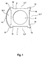
- FIG. 1 shows a sheet laminate 1, which is formed from a base body 2 and a plurality of projections 13 which protrude from the base body radially outwardly.
- the main body 2 which is provided essentially with a square outer contour, has a hole 9 in its center, in which a rotor shaft 22 (FIG. Fig. 3 ) is arranged.
- the main body 2 encloses the rotor shaft 2 completely at its outer radial circumference.
- the projections 13 provided, for example, at corners of the main body 2 form a pocket 3 in which a magnet 24 (FIG. Fig. 3 ) is arranged.
- the sheet laminate 1 has a number n of pockets 3.
- a number of [n-m] pockets where m is less than n and greater than zero, form closed pockets 5 in at least one sheet laminate 1, formed by a web 11 forming two Projections 13 with distance from the main body 2 connects to each other. closed pocket 5.
- the number n is thus four and the number m is three, ie there are three open pockets 7.
- the projections 13 are formed so that the magnetic flux loss is considerably reduced in this edge region.
- directed noses 14 are provided, which lead the magnets quasi selectively and cause a reduction of flux losses.
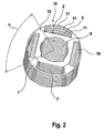
- FIG. 2 shows how the metal laminates 1 are arranged to form a laminated core 15.
- four magnets 24 can be held in the laminated core 15.
- the sheet metal laminates 1 of the laminated core 15 may also be designed so that less but more magnets 24 may be present. Therefore, for example, the directly adjacent sheet metal laminates 1, for example, by an angle of 90 ° (360 ° by number of magnets or n) continuously rotated to each other.
- the directly adjacent sheet metal laminates 1 for example, by an angle of 90 ° (360 ° by number of magnets or n) continuously rotated to each other.
- the sheet metal laminates 1 are connected to each other in a known manner and then form the laminated core 15. It is also only one embodiment of a sheet laminate 1 necessary to form the laminated core 15. At the in FIG. 2 shown embodiment, projections 13 are provided only at two corners of the base body 2 and connected by the web 11.
- the armature 20 is at least formed from a rotor shaft 22, which is arranged in the hole 9 and is fixedly connected to the laminated core 15.
- the magnets 24 are arranged.
- the magnet 24 is, for example, u.a. fixed by a press fit in the pocket 5, 7 of the laminated sheet 1.
- the laminated core 15 is overmolded with the magnets 24, for example by a plastic extrusion coating, whereby the magnet 24 are fixed in the laminated core 15.
- the sheet metal laminates 1 can be fixed by the encapsulation to a laminated core 15.
- the armature 20 according to the invention is not limited to this embodiment.
- two or three closed pockets 5 may be present, in which case the individual sheet metal laminates, for example, are rotated by an angle of 180 °. Any other number of open and closed pockets 3, even with a higher or smaller number of magnets, is conceivable.
- the laminated core 15 locally sheet metal laminates 1 may be present, the only open pockets 7 or only closed pockets 5 have.
- not every sheet laminate 1 must be rotated relative to the directly adjacent sheet laminate 1. It can not be rotated against each other in a laminated core 15 and two or more successive same sheet metal laminates 1, then what then at least one sheet laminate 1 follows, which in turn is rotated with respect to these.
Landscapes
- Engineering & Computer Science (AREA)
- Power Engineering (AREA)
- Iron Core Of Rotating Electric Machines (AREA)
- Permanent Field Magnets Of Synchronous Machinery (AREA)
- Permanent Magnet Type Synchronous Machine (AREA)
Description
- Die Erfindung geht aus von einem Anker nach der Gattung des Anspruchs 1. Eine solcher Anker ist aus
EP-A-0 748 027 bekannt. - Aus der
JP 2000152535 A - Aus der
JP 09046946 A - Aus der
US-PS 2.323.114 ist ein Blechpaket bekannt bei dem die Statorzähne zumindest teilweise voneinander getrennt sind. - Aus der
US-PS 4,777,397 ist ein Anker bekannt, bei dem eine bestimmte Anzahl von Blechlaminaten nur geschlossene Taschen aufweisen, in denen der Magnet zumindest teilweise angeordnet ist. Die anderen Blechlaminate weisen nur offene Taschen auf, so dass der Magnet dort an seinem äußeren Umfang nicht von einem Blech umgeben ist. Die Magnete werden von einem Kleber in den offenen Taschen gesichert.
Hier werden zwei verschiedene Ausführungen von Blechlaminaten benötigt. - Der erfindungsgemäße Anker mit den Merkmalen des Anspruchs 1 hat demgegenüber den Vorteil, dass auf einfache Art und Weise Magnete durch ein Blechpaket fixiert sind und der magnetische Magnetflußverlust reduziert ist.
- Durch die in den abhängigen Ansprüchen aufgeführten Maßnahmen sind vorteilhafte Weiterbildungen und Verbesserungen des im Anspruch 1 genannten Ankers möglich.
- Der Magnet wird nach Anspruch 1 dadurch im Blechpaket fixiert, dass er umspritzt wird. Dies kann beispielsweise durch Kunststoffspritzen erfolgen. So wird auch ein Schutz vor äusseren Umwelteinflüssen gewährleistet.
- Ein Ausführungsbeispiel der Erfindung ist in der Zeichnung vereinfacht dargestellt und in der nachfolgenden Beschreibung näher erläutert.
- Es zeigen
-
Figur 1 ein Blechlaminat für einen erfindungsgemäßen Anker, -
Figur 2 ein Blechpaket, gebildet aus Blechlaminaten gemäßFigur 1 , -
Figur 3 einen erfindungsgemäßen Anker. -
Figur 1 zeigt ein Blechlaminat 1, das aus einem Grundkörper 2 und mehreren Vorsprüngen 13, die von dem Grundkörper radial nach außen hervorstehen, gebildet ist.
Der im wesentlichen mit einer quadratischen Außenkontur versehene Grundkörper 2 weist in seiner Mitte ein Loch 9 auf, in dem eine Rotorwelle 22 (Fig. 3 ) angeordnet ist. Der Grundkörper 2 umschliesst die Rotorwelle 2 vollständig an ihrem äusseren radialen Umfang.
Die beispielsweise an Ecken des Grundkörpers 2 vorgesehenen Vorsprünge 13 bilden eine Tasche 3, in der ein Magnet 24 (Fig. 3 ) angeordnet ist. Das Blechlaminat 1 hat eine Anzahl n von Taschen 3. Eine Anzahl [n - m] Taschen, wobei m kleiner n und grösser als null ist, bilden bei zumindest einem Blechlaminat 1 geschlossene Taschen 5, die dadurch gebildet werden, daß ein Steg 11 zwei Vorsprünge 13 mit Abstand zum Grundkörper 2 miteinander verbindet. geschlossene Tasche 5. Die Zahl n beträgt also vier und die Zahl m beträgt drei, d.h. es gibt drei offene Taschen 7.
Die Vorsprünge 13 sind so ausgebildet, daß der magnetische Flußverlust in diesem Randbereich erheblich reduziert ist. An den Vorsprüngen 13 sind in die Taschen 3 hineingerichtete Nasen 14 vorgesehen, die die Magnete quasi punktuell führen und eine Verminderung von Flußverlusten bewirken. -
Figur 2 zeigt, wie die Blechlaminate 1 zu einem Blechpaket 15 angeordnet sind. In diesem Beispiel können in dem Blechpaket 15 vier Magnete 24 gehalten werden. Die Blechlaminate 1 des Blechpakets 15 können aber auch so ausgebildet sein, dass weniger aber auch mehr Magnete 24 vorhanden sein können.
Deshalb sind bspw. die direkt benachbarten Blechlaminate 1 beispielsweise um einen Winkel von 90° (360° durch Anzahl der Magnete oder n) fortlaufend zueinander verdreht. Durch diese Stapelung der zueinander verdrehten Blechlaminate 1 bilden sich durch die geschlossenen Taschen 5 vier Aufnahmen 18, in denen die Magnete 24 eingeführt werden und radial gesichert werden können.
Durch diese kammartige Struktur des Blechpakets 15 wird der magnetische Flußverlust erheblich reduziert. Die Blechlaminate 1 werden auf bekannte Art und Weise miteinander verbunden und bilden dann das Blechpaket 15. Es ist auch nur eine Ausführung eines Blechlaminats 1 notwendig, um das Blechpaket 15 zu bilden. Bei dem inFigur 2 gezeigten Ausführungsbeispiel sind nur an zwei Ecken des Grundkörpers 2 Vorsprünge 13 vorgesehen und durch den Steg 11 verbunden. - Der Anker 20 wird zumindest gebildet aus einer Rotorwelle 22, die in dem Loch 9 angeordnet ist und mit dem Blechpaket 15 fest verbunden ist. In den Aufnahmen 18 sind die Magnete 24 angeordnet. Der Magnet 24 wird beispielsweise u.a. durch eine Preßpassung in der Tasche 5, 7 des Blechlaminats 1 fixiert. Gemäß Anspruch 1 wird, das Blechpaket 15 mit den Magneten 24 umspritzt, beispielsweise durch eine Kunststoffumspritzung, wodurch der Magnet 24 im Blechpaket 15 fixiert sind. Ebenso können die Blechlaminate 1 durch die Umspritzung zu einem Blechpaket 15 fixiert werden.
- Der erfindungsgemäße Anker 20 ist nicht auf dieses Ausführungsbeispiel beschränkt. Ebenso können bei einer Anzahl von vier Magneten auch zwei oder drei geschlossene Taschen 5 vorhanden sein, wobei dann die einzelnen Blechlaminate bspw. um einen Winkel von 180° gedreht sind. Jede andere Anzahl von offenen und geschlossenen Taschen 3, auch bei einer höheren oder kleineren Anzahl von Magneten, ist denkbar. Ebenso können in dem Blechpaket 15 stellenweise Blechlaminate 1 vorhanden sein, die nur offene Taschen 7 oder nur geschlossene Taschen 5 aufweisen.
Weiterhin muss nicht jedes Blechlaminat 1 gegenüber dem direkt benachbarten Blechlaminat 1 verdreht sein. Es können in einem Blechpaket 15 auch zwei oder mehr aufeinander folgende gleiche Blechlaminate 1 nicht gegeneinander verdreht sein, worauf dann zumindest ein Blechlaminat 1 folgt, das wiederum gegenüber diesen verdreht ist.
Claims (2)
- Anker für eine elektrische Maschine, zumindest bestehend aus einer Rotorwelle, zumindest zwei Blechlaminaten, wobei zumindest ein Blechlaminat zumindest eine geschlossene Tasche aufweist, zumindest einem Magneten, der durch zumindest ein Blechlaminat gehalten ist, wobei der Magnet zumindest teilweise in der geschlossenen Tasche zumindest eines Blechlaminats angeordnet ist, wobei der Anker (20) eine Anzahl n von Magneten (24) aufweist, zumindest ein Blechlaminat (1) eine Anzahl [n-m] geschlossener Taschen (5) aufweist, wobei m kleiner als n und größer als null ist, und wobei zumindest ein Blechlaminat (1) in Umfangsrichtung gegenüber den anderen Blechlaminate (1) verdreht ist und diese zu einem Blechpaket (15) aufgestapelt sind, dadurch gekennzeichnet, dass der Magnet (24) durch Umspritzung des Blechpakets (15) fixiert ist.
- Anker nach Anspruch 1, dadurch gekennzeichnet, dass ein Blechlaminat (1) eine Anzahl m von offenen Taschen aufweist, und dass der Magnet (24) durch Presspassung in zumindest einer Tasche (5,7) des zumindest einen Blechlaminats (1) fixiert ist.
Applications Claiming Priority (3)
| Application Number | Priority Date | Filing Date | Title |
|---|---|---|---|
| DE10056036A DE10056036A1 (de) | 2000-11-11 | 2000-11-11 | Anker |
| DE10056036 | 2000-11-11 | ||
| PCT/DE2001/004210 WO2002039565A1 (de) | 2000-11-11 | 2001-11-12 | Anker mit geschichtetem blechpaket |
Publications (2)
| Publication Number | Publication Date |
|---|---|
| EP1336234A1 EP1336234A1 (de) | 2003-08-20 |
| EP1336234B1 true EP1336234B1 (de) | 2008-09-24 |
Family
ID=7663017
Family Applications (1)
| Application Number | Title | Priority Date | Filing Date |
|---|---|---|---|
| EP01993967A Expired - Lifetime EP1336234B1 (de) | 2000-11-11 | 2001-11-12 | Anker mit geschichtetem blechpaket |
Country Status (7)
| Country | Link |
|---|---|
| US (1) | US7002276B2 (de) |
| EP (1) | EP1336234B1 (de) |
| JP (1) | JP4773039B2 (de) |
| CN (1) | CN1288819C (de) |
| AU (1) | AU2002215848A1 (de) |
| DE (2) | DE10056036A1 (de) |
| WO (1) | WO2002039565A1 (de) |
Families Citing this family (14)
| Publication number | Priority date | Publication date | Assignee | Title |
|---|---|---|---|---|
| ITBO20050437A1 (it) * | 2005-06-30 | 2007-01-01 | Spal Automotive Srl | Rotore per macchina elettrica |
| DE102005041676A1 (de) * | 2005-09-01 | 2007-03-22 | Atb Technologies Gmbh | Blechpaketanordnung für eine elektrische Maschine sowie Rotor und Permanentmagnetmaschine |
| DE102006006882A1 (de) * | 2005-11-21 | 2007-05-24 | Robert Bosch Gmbh | Elektromaschine und Rotor für eine Elektromaschine |
| DE102005059587A1 (de) | 2005-12-14 | 2007-07-05 | Robert Bosch Gmbh | Rotor einer elektrischen Maschine, insbesondere eines Motors, und Verfahren zur Herstellung eines Rotors |
| US7385328B2 (en) * | 2006-05-23 | 2008-06-10 | Reliance Electric Technologies, Llc | Cogging reduction in permanent magnet machines |
| FR2928050B1 (fr) * | 2008-02-26 | 2015-04-10 | Continental Automotive France | Noyau magnetique de machine electrique rotative a fuite reduite |
| WO2009106569A2 (de) * | 2008-02-26 | 2009-09-03 | Brose Fahrzeugteile Gmbh & Co. Kg, Würzburg | Magnetkern einer sich drehenden elektrischen maschine und herstellverfahren |
| FR2928051B1 (fr) * | 2008-02-26 | 2015-07-24 | Continental Automotive France | Noyau magnetique de machine electrique rotative a fuite reduite |
| JP6278333B2 (ja) * | 2013-09-03 | 2018-02-14 | アイシン精機株式会社 | 電動モータ |
| DE102014226171A1 (de) | 2014-12-17 | 2016-06-23 | Robert Bosch Gmbh | Rotor für eine elektrische Maschine |
| DE102015218421A1 (de) * | 2015-09-24 | 2017-03-30 | Continental Automotive Gmbh | Geblechter Magnetanker für eine elektromagnetische Betätigungsvorrichtung sowie Einspritzventil zum Zumessen eines Fluids |
| DE102017203736A1 (de) | 2017-03-07 | 2018-09-13 | Mahle International Gmbh | Elektromotor |
| US11247321B2 (en) * | 2018-04-20 | 2022-02-15 | Ingersoll-Rand Industrial U.S., Inc. | Impact tools with rigidly coupled impact mechanisms |
| CN115632500B (zh) * | 2022-11-11 | 2026-04-03 | 珠海格力电器股份有限公司 | 一种定子冲片、定子铁芯、定子及电机 |
Family Cites Families (16)
| Publication number | Priority date | Publication date | Assignee | Title |
|---|---|---|---|---|
| US2323114A (en) | 1942-02-26 | 1943-06-29 | Gen Motors Corp | Pole piece assembly |
| US4469970A (en) * | 1981-12-24 | 1984-09-04 | General Electric Company | Rotor for permanent magnet excited synchronous motor |
| JPS62226264A (ja) * | 1986-03-28 | 1987-10-05 | Nec Corp | マルチプロセツサシステムのデ−タ転送遅延時間選択方式 |
| US4777397A (en) | 1986-08-15 | 1988-10-11 | Marathon Electric Manufacturing Corp. | Permanent magnet generator apparatus including a consequent pole rotor |
| GB2217924B (en) * | 1988-04-25 | 1992-10-07 | Matsushita Electric Works Ltd | Permanent magnet rotor |
| JPH06133479A (ja) * | 1992-09-02 | 1994-05-13 | Toshiba Corp | 永久磁石ロータ及びその製造装置 |
| JPH08331784A (ja) * | 1995-03-24 | 1996-12-13 | Hitachi Metals Ltd | 永久磁石界磁方式回転機 |
| DE69636505T2 (de) * | 1995-06-07 | 2007-05-24 | General Electric Co. | Dynamoelektrische Maschine und deren Rotorkonstruktion |
| JPH0946946A (ja) | 1995-07-28 | 1997-02-14 | Aichi Emerson Electric Co Ltd | 磁石回転子 |
| JP3277780B2 (ja) * | 1995-12-07 | 2002-04-22 | 松下電器産業株式会社 | 永久磁石埋め込み形モータにおける永久磁石の固定方法 |
| JP3493865B2 (ja) | 1995-12-27 | 2004-02-03 | アイシン・エィ・ダブリュ株式会社 | モータ |
| JPH09327140A (ja) * | 1996-06-07 | 1997-12-16 | Hitachi Ltd | 永久磁石回転型回転電機及びその製造方法 |
| JPH1189130A (ja) * | 1997-09-08 | 1999-03-30 | Minebea Co Ltd | モータ構造 |
| DE69839927D1 (de) | 1997-10-13 | 2008-10-02 | Matsushita Electric Industrial Co Ltd | Motor mit innerem Permanentmagnetrotor |
| JP2000152535A (ja) | 1998-11-12 | 2000-05-30 | Fuji Electric Co Ltd | 永久磁石電動機の回転子 |
| JP2000197291A (ja) | 1998-12-25 | 2000-07-14 | Fuji Electric Co Ltd | 永久磁石式同期機 |
-
2000
- 2000-11-11 DE DE10056036A patent/DE10056036A1/de not_active Withdrawn
-
2001
- 2001-11-12 AU AU2002215848A patent/AU2002215848A1/en not_active Abandoned
- 2001-11-12 JP JP2002541773A patent/JP4773039B2/ja not_active Expired - Fee Related
- 2001-11-12 CN CN01818643.2A patent/CN1288819C/zh not_active Expired - Fee Related
- 2001-11-12 EP EP01993967A patent/EP1336234B1/de not_active Expired - Lifetime
- 2001-11-12 DE DE50114354T patent/DE50114354D1/de not_active Expired - Lifetime
- 2001-11-12 US US10/415,227 patent/US7002276B2/en not_active Expired - Fee Related
- 2001-11-12 WO PCT/DE2001/004210 patent/WO2002039565A1/de not_active Ceased
Also Published As
| Publication number | Publication date |
|---|---|
| CN1288819C (zh) | 2006-12-06 |
| AU2002215848A1 (en) | 2002-05-21 |
| WO2002039565A1 (de) | 2002-05-16 |
| CN1473384A (zh) | 2004-02-04 |
| JP2004514388A (ja) | 2004-05-13 |
| US7002276B2 (en) | 2006-02-21 |
| DE50114354D1 (de) | 2008-11-06 |
| JP4773039B2 (ja) | 2011-09-14 |
| US20040047090A1 (en) | 2004-03-11 |
| DE10056036A1 (de) | 2002-05-29 |
| EP1336234A1 (de) | 2003-08-20 |
Similar Documents
| Publication | Publication Date | Title |
|---|---|---|
| DE69211390T2 (de) | Geschalteter Reluktanzmotor mit aus isolierten Segmenten bestehendem Rotor | |
| DE69409889T2 (de) | Rotor eines synchronmotors | |
| DE10392673B4 (de) | Elektrischer Motor mit Permanentmagneten | |
| EP1336234A1 (de) | Anker mit geschichtetem blechpaket | |
| DE102010004887A1 (de) | Spulenkörper zur Montage an einem Magnetkern, Magnetkern für Reluktanzresolver und Verfahren zur Herstellung | |
| DE10227859A1 (de) | Induktionsmotor vom Typ mit eingebettetem Permanentmagneten, welcher leichte Durchführung der Einbettung der Spule gestattet | |
| DE1941180A1 (de) | Gleichstrom-Dynamo | |
| DE112007000201T5 (de) | Geschlitzte Kerne für einen Motorstator, Motorstator, Synchronmotor des Permanentmagnetentyps, und Stanzverfahren durch Stanzstempel für geschlitzte Kerne | |
| DE102008032844A1 (de) | Permanentmagnetischer Rotor | |
| DE102009060972A1 (de) | Elektromotor | |
| DE102011105872A1 (de) | Motor und rotor | |
| DE102015212821A1 (de) | Statoranordnung, elektrische Drehstrommaschine und Verfahren zum Herstellen einer Statoranordnung | |
| DE102012218117A1 (de) | Elektrische Rotationsmaschine | |
| DE102012021042A1 (de) | Rotor und Motor | |
| DE2020780A1 (de) | Elektrischer Gleichstrommotor | |
| EP3552301B1 (de) | Verfahren zur herstellung eines rotors für eine synchronreluktanzmaschine sowie rotor für eine synchronreluktanzmaschine | |
| DE102012100332A1 (de) | Stator für eine rotierende elektrische Maschine und Verfahren zu seiner Herstellung | |
| DE102007038668A1 (de) | Elektromotor, insbesondere Synchronmotor | |
| EP3381107B1 (de) | Elektroblech mit gedrucktem steg | |
| DE102017102242A1 (de) | Verwendung von magnetfeldern in elektromaschinen | |
| EP1746707A1 (de) | Permanentmagneterregte bürstenlose Synchronmaschine mit eingebetteten Magneten und mit trapezförmig verlaufender elektromagnetischer Kraft | |
| DE102007029144A1 (de) | Statorkern | |
| DE102023101128A1 (de) | Resolverstator | |
| DE102015111483A1 (de) | Mehrfach-Lundell-Motor | |
| DE60320165T2 (de) | Drehende elektrische Maschine |
Legal Events
| Date | Code | Title | Description |
|---|---|---|---|
| PUAI | Public reference made under article 153(3) epc to a published international application that has entered the european phase |
Free format text: ORIGINAL CODE: 0009012 |
|
| 17P | Request for examination filed |
Effective date: 20030611 |
|
| AK | Designated contracting states |
Designated state(s): AT BE CH CY DE DK ES FI FR GB GR IE IT LI LU MC NL PT SE TR |
|
| RBV | Designated contracting states (corrected) |
Designated state(s): DE ES FR GB IT |
|
| GRAP | Despatch of communication of intention to grant a patent |
Free format text: ORIGINAL CODE: EPIDOSNIGR1 |
|
| GRAS | Grant fee paid |
Free format text: ORIGINAL CODE: EPIDOSNIGR3 |
|
| GRAA | (expected) grant |
Free format text: ORIGINAL CODE: 0009210 |
|
| AK | Designated contracting states |
Kind code of ref document: B1 Designated state(s): DE ES FR GB IT |
|
| REG | Reference to a national code |
Ref country code: GB Ref legal event code: FG4D Free format text: NOT ENGLISH |
|
| REF | Corresponds to: |
Ref document number: 50114354 Country of ref document: DE Date of ref document: 20081106 Kind code of ref document: P |
|
| PG25 | Lapsed in a contracting state [announced via postgrant information from national office to epo] |
Ref country code: ES Free format text: LAPSE BECAUSE OF FAILURE TO SUBMIT A TRANSLATION OF THE DESCRIPTION OR TO PAY THE FEE WITHIN THE PRESCRIBED TIME-LIMIT Effective date: 20090104 |
|
| PLBE | No opposition filed within time limit |
Free format text: ORIGINAL CODE: 0009261 |
|
| STAA | Information on the status of an ep patent application or granted ep patent |
Free format text: STATUS: NO OPPOSITION FILED WITHIN TIME LIMIT |
|
| GBPC | Gb: european patent ceased through non-payment of renewal fee |
Effective date: 20081224 |
|
| PG25 | Lapsed in a contracting state [announced via postgrant information from national office to epo] |
Ref country code: IT Free format text: LAPSE BECAUSE OF FAILURE TO SUBMIT A TRANSLATION OF THE DESCRIPTION OR TO PAY THE FEE WITHIN THE PRESCRIBED TIME-LIMIT Effective date: 20080924 |
|
| 26N | No opposition filed |
Effective date: 20090625 |
|
| PG25 | Lapsed in a contracting state [announced via postgrant information from national office to epo] |
Ref country code: GB Free format text: LAPSE BECAUSE OF NON-PAYMENT OF DUE FEES Effective date: 20081224 |
|
| REG | Reference to a national code |
Ref country code: FR Ref legal event code: PLFP Year of fee payment: 15 |
|
| REG | Reference to a national code |
Ref country code: FR Ref legal event code: PLFP Year of fee payment: 16 |
|
| PGFP | Annual fee paid to national office [announced via postgrant information from national office to epo] |
Ref country code: FR Payment date: 20161124 Year of fee payment: 16 |
|
| REG | Reference to a national code |
Ref country code: DE Ref legal event code: R084 Ref document number: 50114354 Country of ref document: DE |
|
| PGFP | Annual fee paid to national office [announced via postgrant information from national office to epo] |
Ref country code: DE Payment date: 20180125 Year of fee payment: 17 |
|
| REG | Reference to a national code |
Ref country code: FR Ref legal event code: ST Effective date: 20180731 |
|
| PG25 | Lapsed in a contracting state [announced via postgrant information from national office to epo] |
Ref country code: FR Free format text: LAPSE BECAUSE OF NON-PAYMENT OF DUE FEES Effective date: 20171130 |
|
| REG | Reference to a national code |
Ref country code: DE Ref legal event code: R119 Ref document number: 50114354 Country of ref document: DE |
|
| PG25 | Lapsed in a contracting state [announced via postgrant information from national office to epo] |
Ref country code: DE Free format text: LAPSE BECAUSE OF NON-PAYMENT OF DUE FEES Effective date: 20190601 |