EP1336230B1 - Steckverbinder für geschirmte daten- und/oder telekommunikations-kabel - Google Patents
Steckverbinder für geschirmte daten- und/oder telekommunikations-kabel Download PDFInfo
- Publication number
- EP1336230B1 EP1336230B1 EP01983591A EP01983591A EP1336230B1 EP 1336230 B1 EP1336230 B1 EP 1336230B1 EP 01983591 A EP01983591 A EP 01983591A EP 01983591 A EP01983591 A EP 01983591A EP 1336230 B1 EP1336230 B1 EP 1336230B1
- Authority
- EP
- European Patent Office
- Prior art keywords
- connector
- plug
- cable
- contact
- shielding
- Prior art date
- Legal status (The legal status is an assumption and is not a legal conclusion. Google has not performed a legal analysis and makes no representation as to the accuracy of the status listed.)
- Expired - Lifetime
Links
- 239000002184 metal Substances 0.000 claims abstract description 6
- 229910052751 metal Inorganic materials 0.000 claims abstract description 6
- 238000006073 displacement reaction Methods 0.000 description 8
- 238000009413 insulation Methods 0.000 description 8
- 238000003780 insertion Methods 0.000 description 6
- 230000037431 insertion Effects 0.000 description 6
- 238000009434 installation Methods 0.000 description 4
- 238000004519 manufacturing process Methods 0.000 description 3
- HCHKCACWOHOZIP-UHFFFAOYSA-N Zinc Chemical compound [Zn] HCHKCACWOHOZIP-UHFFFAOYSA-N 0.000 description 2
- 238000005452 bending Methods 0.000 description 2
- 239000004020 conductor Substances 0.000 description 2
- 238000010276 construction Methods 0.000 description 2
- 238000004080 punching Methods 0.000 description 2
- 229910052725 zinc Inorganic materials 0.000 description 2
- 239000011701 zinc Substances 0.000 description 2
- 230000005540 biological transmission Effects 0.000 description 1
- 210000001503 joint Anatomy 0.000 description 1
- 239000000463 material Substances 0.000 description 1
- 230000013011 mating Effects 0.000 description 1
- 230000002093 peripheral effect Effects 0.000 description 1
Images





Classifications
-
- H—ELECTRICITY
- H01—ELECTRIC ELEMENTS
- H01R—ELECTRICALLY-CONDUCTIVE CONNECTIONS; STRUCTURAL ASSOCIATIONS OF A PLURALITY OF MUTUALLY-INSULATED ELECTRICAL CONNECTING ELEMENTS; COUPLING DEVICES; CURRENT COLLECTORS
- H01R13/00—Details of coupling devices of the kinds covered by groups H01R12/70 or H01R24/00 - H01R33/00
- H01R13/648—Protective earth or shield arrangements on coupling devices, e.g. anti-static shielding
- H01R13/658—High frequency shielding arrangements, e.g. against EMI [Electro-Magnetic Interference] or EMP [Electro-Magnetic Pulse]
- H01R13/6591—Specific features or arrangements of connection of shield to conductive members
- H01R13/6592—Specific features or arrangements of connection of shield to conductive members the conductive member being a shielded cable
-
- H—ELECTRICITY
- H01—ELECTRIC ELEMENTS
- H01R—ELECTRICALLY-CONDUCTIVE CONNECTIONS; STRUCTURAL ASSOCIATIONS OF A PLURALITY OF MUTUALLY-INSULATED ELECTRICAL CONNECTING ELEMENTS; COUPLING DEVICES; CURRENT COLLECTORS
- H01R13/00—Details of coupling devices of the kinds covered by groups H01R12/70 or H01R24/00 - H01R33/00
- H01R13/648—Protective earth or shield arrangements on coupling devices, e.g. anti-static shielding
- H01R13/658—High frequency shielding arrangements, e.g. against EMI [Electro-Magnetic Interference] or EMP [Electro-Magnetic Pulse]
- H01R13/6581—Shield structure
- H01R13/6582—Shield structure with resilient means for engaging mating connector
Definitions
- the invention relates to a connector for shielded data and / or telecommunication cables according to the preamble of claim 1.
- shielded cables are usually used to prevent the radiating of high-frequency signals and the capture of high-frequency interference.
- care must therefore be taken to ensure that shielding is also ensured in the area of the plug connector.
- Shielded housings are therefore used for the plug connectors which shield both the plug connection contacts and the connection of the wires of the cable.
- the shield of the cable must be passed through the housing and the connector to the shield of a cable to be connected.
- a shield contact is provided in known connectors, which comes into conductive contact with the shield of the cable and is in conductive connection with at least one contact bracket of the connector.
- the invention has the object to improve a connector of the type mentioned input so that this one hand in production and installation is easy and on the other hand ensures a reliable transfer of the shielding.
- the shield of the cable is a one-piece Shield used, which is manufactured as a punch-bending part.
- the shroud is made of a spring metal.
- the shield contact is designed as at least one resilient Schirmab fortunelasche that comes when mating the connector housing under its spring elasticity to rest against the shield of the connected cable. This ensures a good conductive contact between the shroud and the shield of the cable without additional installation action.
- a contact spring tab is integrally formed on the shield plate further in one piece, which is guided out of the housing of the connector to the outside.
- the connector is particularly suitable for installation in a mounting plate, for. B. in the mounting plate of a patch panel or a device.
- the shield plate is simultaneously used by training suitable retaining tabs to hold the contact carrier in the connector housing and position.
- the connector is shown in the form of a Western connector socket. It is obvious that the invention can be implemented in a corresponding manner also in connector plugs and in other types of connectors.
- the connector is used to connect a multi-core data or telecommunications cable 10, in the illustrated embodiment, a cable 10 with eight wires 12.
- the cable 10 is shielded, including in particular the cable 10 is enclosed by a conductive braided shield 14.
- the connector consists of a top 16 and a bottom 18, which are constructed and mounted in the manner described below. Construction and assembly of the upper part 16 is in particular in the FIGS. 1 to 3 shown during assembly and assembly of the lower part 18 in particular from the FIGS. 4 to 7 emerge.
- the upper part 16 has an upper housing shell 20, which preferably consists of an electrically conductive material and in particular as a metallic die cast part, e.g. is produced as a zinc die-cast part.
- the upper housing shell 20 consists of an upper cover plate 22 to which right-angled side cheeks 24 are formed, so that there is a U-shaped box profile.
- a loading piece 26 is inserted from plastic, including guide webs 28 are formed on the inside of the side walls 24, which engage in corresponding guide grooves 26 of the loading piece. In the inserted state, the loading piece 26 engages with lateral detent springs 29 in recesses of the side cheeks 24.
- the charging piece 26 has the same rectangular profile in cross section as the inner profile cross section of the upper housing shell 20, as in FIG. 3 can be seen. In longitudinal section, the charging piece 26 is stepped. An upper portion 30 of the loading piece 26 abutting the cover plate 22 extends substantially the entire length of the U-shaped inner profile of the upper housing shell 20. A lower portion 32 is shorter in the axial direction, the end face of this lower portion 32 being stepped the end surface of the upper portion 30 is reset. The rear rear surface of the charging piece 26 is continuous over its entire height. The height of sections 30 and 32 is in each case about half the height of the entire loading piece 26.
- the charging piece 26 serves to receive the cores 12 of the cable 10.
- the charging piece 26 has in its upper portion 30 four axially spaced bores 34 spaced apart in one plane, in which four of the eight cores 12 of the cable 10 from the rear side of the cable 10 Loading pieces 26 are introduced as best in FIG. 2 you can see.
- the lower portion 32 has four axially continuous grooves 36 which are open towards the lower surface of the lower portion 32.
- the grooves 36 have the same mutual distance on how the holes 34 and are arranged in a corresponding position.
- the grooves 36 serve to insert the other four wires 12, as shown in the FIGS. 1 to 3 is apparent.
- the loading piece 26 has in its upper portion 30 inlet slots 38 which extend from the exposed lower surface of the upper portion 30 in front of the lower portion 32 and lead into the upper portion 30 and each pass through the holes 34.
- the lower section 32 has entry slots 40, which emanate from its lower side and respectively cross the channels 36. The entry slots 38 and 40 serve in the manner described later for the introduction of insulation displacement contacts.
- the upper cover plate 22 of this housing shell 20 is reinforced and formed with a longitudinally extending central recess 42, in which the cable 10 is inserted.
- a T-shaped projection 44 is integrally formed above the trough 42 in the axial extension of the housing shell 20.
- the assembly of the upper part 16 of the connector is done in the following manner:
- the wires 12 of the cable 10 are exposed. Further, following the exposed wires 12, the outer insulation of the cable 10 is removed, so that over a certain length the braided shield 14 is exposed. Now four of the wires 12 are inserted into the holes 34 of the charging piece 26 and then inserted the remaining four wires 12 in the grooves 36, wherein inside projecting ribs 37 of these grooves 36 hold the wires 12 clamped. Subsequently, the charging piece 26 connected in this way to the cable 10 is inserted from the front end side by means of the guide webs 28 into the upper housing shell 20 and locked by means of the locking springs 29. The cable 10 with its exposed braided shield 14 comes to lie in the trough 42.
- the lower part 18 has a lower housing shell 48 which is preferably metallically conductive in the same way as the upper housing shell 20 and is preferably made as a metal die cast part, in particular as a zinc die cast part.
- the lower housing shell 48 is box-shaped in such a way that it is supplemented by the upper housing shell 20 to a closed shielding housing.
- the shape of the lower shell 48 is most apparent in FIG FIG. 4 to recognize.
- the lower housing shell 48 has a lower base plate 50, on which side walls 52 leading at right angles are formed. In the side cheeks 52 cutouts 54 are provided which correspond in shape to the side cheeks 24 of the upper housing shell 20. In the front area, the lower housing shell 48 is closed at the top. In the front end face of the lower housing shell 48, an insertion opening 56 is recessed, which serves for the insertion of a Western plug.
- a contact carrier 58 made of plastic is inserted axially from the rear side.
- the width of the contact carrier 58 corresponds to the width of the inner cross section of the housing shell 48.
- the contact carrier 58 has eight connector contacts 60 arranged next to one another. Is the contact carrier 58 completely inserted into the lower housing shell 48, as in FIG. 6 is shown, the connector contacts 60 are in conventional Way behind the insertion opening 56 to contact a plugged into this insertion port 56 Western plug.
- the contact carrier 58 In the rear region of the contact carrier 58 is step-shaped in a step-shaped configuration of the charging piece 26 corresponding shape. In this area, the contact carrier 58 carries at its top two rows of juxtaposed insulation displacement contacts 62.
- Each of these insulation displacement contacts 62 is conductively connected to one of the connector contacts 60.
- the insulation displacement contacts 62 are arranged on the stepped upper side of the contact carrier 58 so that they penetrate when placing the charging piece 26 on the contact carrier 58 in the inlet slots 38 and 40 of the charging piece 26.
- the contact body 58 made of insulating plastic is inserted into a shield plate 64 and is inserted together with this shield plate 64 in the lower housing shell 48.
- the shape and the manufacture of the shielding plate 64 is in the Figures 9 and 10 shown.
- the shield plate 64 is a one-piece stamped and bent part made of a conductive spring metal. First, the shield plate 64 in the in FIG. 9 punched out form shown. From this stamped part, the shield plate 64 is connected to the in FIG. 9 drawn bending lines in the in FIG. 10 bent shape shown.
- the shield plate 64 has a base plate 66, on which the contact carrier 58 is placed. From the base plate 66, a rear retaining tab 68 is punched out and bent up in its central rear region. In the middle region of the longitudinal extent of the in FIG. 9 shown punching part protrude on either side at right angles side arms 70, which are bent upwards from the base plate 66 at right angles. Of these side arms 70 each protrudes from a front retaining tab 72 which protrudes from the side arm 70 to the rear and in the in FIG. 10 shown curved state is angled inwardly at its end.
- the contact carrier 58 is placed on the base plate 66, wherein the rear retaining tab 68 with its upper parallel to the base plate 66 angled end the contact carrier 58 is supported to the rear and holds on the base plate 66. Laterally, the contact carrier 58 is guided between the side arms 70 and fixed by the inwardly angled front retaining tabs 72 against displacement forward, as can be seen from FIG. 4 is apparent.
- the contact carrier 58 is placed on the base plate 66 and positioned between the rear retaining tab 68, the side arms 70 and the front retaining tabs 72 and fixed to the shield plate 64.
- the contact spring tab 76 is not bent yet. This situation is in FIG. 4 shown.
- the shield plate 64 is pushed with the contact carrier 58 from the rear axially into the lower housing shell 48, like this FIG. 5 shows.
- the not yet bent contact spring tab 76 exits through a slot 84 of the lower housing shell 48, which is provided in the front end of the lower housing shell 48 above the bottom plate 50.
- the connector contacts 60 of the contact carrier 58 are located in the connector receptacle of the lower housing shell 48 behind the insertion opening 56th Die Forward facing contact bars 74 are located on both sides in the plug receptacle behind the insertion opening 56 to contact the side shield contacts of an inserted plug.
- the insulation displacement contacts 62 are located in the open top region of the lower shell 48.
- the inwardly bent Schirmab fortunelaschen 80 are located behind the cutouts 54 in the rear end of the lower housing shell 48.
- the shield plate 82 closes the lower housing shell 48 shielding below the Schirmabnahiltaschen 80 from. In this position, the contact carrier 58 is latched to the lower housing shell 48, including on both sides of the contact carrier 58 integrally formed latching projections 86 snap into locking recesses 88 of the side walls 52 of the lower housing shell 48.
- the contact spring tab 76 After locking the contact carrier 58 and thus the shield plate 64 in the lower housing shell 48, the contact spring tab 76 is bent at the front end side of the housing shell 48 down and to the rear, like this FIG. 7 shows.
- the contact spring tab 76 has the shape of a triangle in the curved shape, which is supported on the one hand on the slot 84 and the free end of the contact spring tab 76 on the bottom plate 50.
- the apex of the triangular-shaped contact spring tab 76 is resiliently formed in this way against the bottom plate 50.
- both the upper part 16 and the lower part 18 are fully assembled. It is now the upper part 16 is inserted into the lower part 18, wherein the side cheeks 24 of the upper housing shell 20 are inserted into the cutouts 54 of the side walls 52 of the lower housing shell 48.
- the side cheeks 24 and 52 are stepped at their circumference, so that between the side cheeks 24 and 52 is formed from the inside outward continuous butt joint.
- the upper housing shell 20 and the lower housing shell 48 are locked together, for which purpose 20 locking projections 90 are integrally formed laterally on the upper housing shell, which engage in locking recesses 92 in the rear region of the side walls 52 of the lower housing shell 48.
- the cable 10 When placing the upper part 16 on the lower part 18, the cable 10 is also pressed with its exposed braid 14 on the Schirmabnahehtaschen 80.
- the cable 10 is supported with its braided shield 14 on the one hand by the trough 42 of the upper housing shell 20 and on the other hand pressed against the resilient Schirmabnahiltaschen 80.
- a good conductive electrical contact is made on the one hand with the upper housing shell 20 and on the other hand via the Schirmabnahiltaschen 80 with the shield plate 64.
- the shield On the one-piece shield plate 64, the shield is on the one hand passed to the contact bracket 74, which come into contact with the shield of an inserted plug.
- the shield is transmitted in one piece to the contact spring tab 76.
- the connector is inserted into a mounting plate 94, which consists of an electrically conductive material and is at ground potential.
- the mounting plate 94 may be, for example, the front panel of a patch panel or the mounting plate of a device.
- the mounting plate 94 has a cutout which corresponds in cross section to the cross section of the connector and in particular the front side of the lower housing shell 48.
- two outer abutment protrusions 96 are integrally formed adjacent to the front-side leading edge.
- a counter-projection 98 is formed on the upper side of the lower housing shell 48.
- the abutment 98 corresponding distance from the front-side front edge of the lower housing shell 48 integrally formed abutment projections 100.
- the assembled connector is inserted into the cutout of the mounting plate 94 in the following manner.
- the upper end edge of the lower housing shell 48 is inserted into the cutout and guided upward so that the abutment protrusions 96 are located on the front of the mounting plate 94 and the counter projection 98 on the rear side of the mounting plate 94. Then, the lower end edge of the housing shell 48 is pressed from behind into the cutout of the mounting plate 94 until the lower abutment projections 100 abut the rear of the mounting plate 94. In this case, the contact spring tab 76 engages in a peripheral cutout 104 of the cutout of the mounting plate 94 and is pressed by the lower edge of this edge cutout 104 against the bottom plate 50.
- the contact spring tab 76 then engages with trained on both sides of the contact spring tab 76 stages 102 in front of the mounting plate 94, whereby the connector is completely engaged and held in the cutout of the mounting plate 94. If the connector from the mounting plate 94 are released again, so only on the back of the mounting plate 94, the contact spring tab 76 by hand against the bottom plate 50 are pressed so that the steps 102 of the contact spring tab 76 from this contact spring tab 76 receiving edge cutout 104 are lifted ,
- the contact spring tab 76 of the shield plate 64 presses resiliently against the lower edge of the cutout of the mounting plate 94 and thus provides a good ground contact of the shield plate 64, whereby the ground contact with the shield braid 14 of the cable 10 and an inserted plug is made.
Landscapes
- Details Of Connecting Devices For Male And Female Coupling (AREA)
- Processing Of Terminals (AREA)
- Communication Cables (AREA)
Description
- Die Erfindung betrifft einen Steckverbinder für geschirmte Daten- und/oder Telekommunikations-Kabel gemäss dem Oberbegriff des Anspruchs 1.
- Für Daten- und/oder Telekommunikations-Netze werden in der Regel geschirmte Kabel verwendet, um das Abstrahlen von Hochfrequenz-Signalen und das Auffangen von Hochfrequenz-Störungen zu verhindern. Bei Steckverbindungen solcher Kabel muss dementsprechend dafür gesorgt werden, dass eine Abschirmung auch im Bereich des Steckverbinders gewährleistet ist. Es werden daher für die Steckverbinder abgeschirmte Gehäuse verwendet, die sowohl die Steckverbindungskontakte als auch den Anschluss der Adern des Kabels abschirmen. Die Schirmung des Kabels muss über das Gehäuse und die Steckverbindung an die Schirmung eines anzuschließenden Kabels weitergegeben werden. Hierzu ist bei bekannten Steckverbindern ein Schirmkontakt vorgesehen, der mit der Schirmung des Kabels in leitende Berührung kommt und mit wenigstens einem Kontaktbügel der Steckverbindung in leitender Verbindung steht.
- Als Stand der Technik werden die
US 5,820,412 sowie dieEP 0 600 120 A1 genannt. - Der Erfindung liegt die Aufgabe zugrunde, einen Steckverbinder der Eingangs genannten Gattung so zu verbessern, dass dieser einerseits in Herstellung und Montage einfach ist und andererseits eine zuverlässige Weitergabe der Schirmung gewährleistet.
- Diese Aufgabe wird erfindungsgemäß gelöst durch einen Steckverbinder mit den Merkmalen des Anspruchs 1.
- Vorteilhafte Ausführungen der Erfindung sind in den Unteransprüchen angegeben.
- Erfindungsgemäß wird für die Weitergabe der Schirmung von dem Kabel zu dem Kontakt der Steckverbindung ein einstückiges Schirmblech verwendet, welches als Stanz-Biege-Teil hergestellt wird. Dadurch ist zum einen eine kostengünstige Herstellung und eine einfache Montage möglich und zum anderen ist eine zuverlässige leitende Verbindung zwischen der Schirmung des Kabels und dem Schirmkontakt der Steckverbindung ohne Übergangswiderstände gewährleistet. Vorzugsweise ist das Schirmblech aus einem Federmetall hergestellt. Der Schirmkontakt ist als wenigstens eine federnde Schirmabnahmelasche ausgebildet, die beim Zusammenfügen des Steckverbindergehäuses unter ihrer Federelastizität zur Anlage an der Schirmung des angeschlossenen Kabels kommt. Dadurch ist ein gut leitender Kontakt zwischen dem Schirmblech und der Schirmung des Kabels ohne zusätzlicher Montagemaßnahme sichergestellt.
- In einer vorteilhaften Ausführung der Erfindung ist an dem Schirmblech weiter einstückig eine Kontaktfederlasche angeformt, die aus dem Gehäuse des Steckverbinders nach außen geführt ist. In dieser Ausführung eignet sich der Steckverbinder insbesondere zum Einbau in eine Montageplatte, z. B. in die Montageplatte eines Patch-Panels oder eines Gerätes. Beim Einbau des Steckverbinders in eine solche Montageplatte kommt die außen an dem Gehäuse angeordnete Kontaktfederlasche in federnden Kontakt mit der Montageplatte, so dass ein zuverlässiger Massekontakt der Schirmung mit der Montageplatte gewährleistet ist. Um die Montage des Steckverbinders zu vereinfachen, wird in einer weiteren Ausführung das Schirmblech durch Ausbildung geeigneter Haltelaschen gleichzeitig dazu verwendet, den Kontaktträger in dem Steckverbinder-Gehäuse zu halten und zu positionieren.
- Im Folgenden wird die Erfindung anhand eines in der Zeichnung dargestellten Ausführungsbeispiels näher erläutert. Es zeigen:
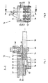
- Figur 1
- perspektivisch das Oberteil des Steckverbinders,
- Figur 2
- einen Längsschnitt des Oberteils gemäß der Schnittlinie A-A in
Figur 3 , - Figur 3
- eine Stirnansicht des Oberteils,
- Figuren 4 bis 7
- in aufeinanderfolgenden Schritten die Montage des Unterteils des Steckverbinders,
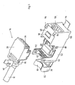
- Figur 8
- in perspektivischer Ansicht den montierten Steckverbinder,
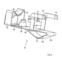
- Figur 9
- das Schirmblech des Steckverbinders als Stanzteil,
- Figur 10
- das Schirmblech des Steckverbinders im gebogenen Zustand,
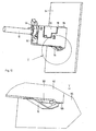
- Figur 11
- den in eine Montageplatte eingesetzten Steckverbinder in Vorderansicht und
- Figur 12
- den in die Montage eingesetzten Steckverbinder in Rückansicht.
- In dem Ausführungsbeispiel ist der Steckverbinder in Form einer Western-Steckverbinder-Buchse dargestellt. Es ist offensichtlich, daß die Erfindung in entsprechender Weise auch bei Steckverbinder-Steckern und bei anderen Typen von Steckverbindungen realisiert werden kann.
- Der Steckverbinder dient zum Anschließen eines mehradrigen Daten- oder Telekommunikationskabels 10, im dargestellten Ausführungsbeispiel eines Kabels 10 mit acht Adern 12. Das Kabel 10 ist geschirmt, wozu insbesondere das Kabel 10 durch ein leitendes Schirmgeflecht 14 umschlossen ist.
- Der Steckverbinder besteht aus einem Oberteil 16 und einem Unterteil 18, die in der nachfolgend beschriebenen Weise aufgebaut sind und montiert werden. Aufbau und Montage des Oberteils 16 ist insbesondere in den
Figuren 1 bis 3 gezeigt, während Aufbau und Montage des Unterteils 18 insbesondere aus denFiguren 4 bis 7 hervorgehen. - Das Oberteil 16 weist eine obere Gehäuseschale 20 auf, die vorzugsweise aus einem elektrisch leitenden Werkstoff besteht und insbesondere als metallisches Druckgußteil, z.B. als Zink-Druckgußteil hergestellt ist. Die obere Gehäuseschale 20 besteht aus einer oberen Deckplatte 22, an welche rechtwinklig Seitenwangen 24 angeformt sind, so dass sich ein U-förmiges Kastenprofil ergibt. In dieses Kastenprofil der oberen Gehäuseschale 20 wird ein Ladestück 26 aus Kunststoff eingeschoben, wozu Führungsstege 28 innen an den Seitenwangen 24 ausgebildet sind, die in entsprechende Führungsnuten des Ladestückes 26 eingreifen. Im eingeschobenen Zustand rastet das Ladestück 26 mit seitlichen Rastfedern 29 in Aussparungen der Seitenwangen 24 ein.
- Das Ladestück 26 weist im Querschnitt dasselbe rechteckige Profil auf wie der Innenprofilquerschnitt der oberen Gehäuseschale 20, wie in
Figur 3 zu erkennen ist. Im Längsschnitt ist das Ladestück 26 stufenförmig ausgebildet. Ein an der Deckplatte 22 anliegender oberer Abschnitt 30 des Ladestückes 26 erstreckt sich im Wesentlichen über die gesamte Länge des U-förmigen Innenprofils der oberen Gehäuseschale 20. Ein unterer Abschnitt 32 ist in axialer Richtung kürzer ausgebildet, wobei die Stirnfläche dieses unteren Abschnittes 32 stufenförmig gegenüber der Stirnfläche des oberen Abschnittes 30 zurückgesetzt ist. Die hintere Rückfläche des Ladestückes 26 ist über dessen gesamten Höhe durchgehend. Die Höhe der Abschnitte 30 und 32 beträgt jeweils etwa die halbe Höhe des gesamten Ladestückes 26. - Das Ladestück 26 dient zur Aufnahme der Adern 12 des Kabels 10. Hierzu weist das Ladestück 26 in seinem oberen Abschnitt 30 vier in einer Ebene beabstandete nebeneinander angeordnete axial durchgehende Bohrungen 34 auf, in welchen vier der acht Adern 12 des Kabels 10 von der Rückseite des Ladestückes 26 eingeführt werden, wie dies am besten in
Figur 2 zu sehen ist. Der untere Abschnitt 32 weist vier in Axialrichtung durchgehende Rinnen 36 auf, die gegen die untere Fläche des unteren Abschnittes 32 hin offen sind. Die Rinnen 36 weisen denselben gegenseitigen Abstand auf wie die Bohrungen 34 und sind in einer entsprechenden Position angeordnet. Die Rinnen 36 dienen zum Einlegen der anderen vier Adern 12, wie dies in denFiguren 1 bis 3 ersichtlich ist. Das Ladestück 26 weist in seinem oberen Abschnitt 30 Eintrittsschlitze 38 auf, die von der freiliegenden unteren Fläche des oberen Abschnittes 30 vor dem unteren Abschnitt 32 ausgehen und in den oberen Abschnitt 30 hineinführen und jeweils die Bohrungen 34 durchqueren. Entsprechend weist der untere Abschnitt 32 Eintrittsschlitze 40 auf, die von dessen unterer Seite ausgehen und jeweils die Rinnen 36 queren. Die Eintrittsschlitze 38 und 40 dienen in später beschriebener Weise zum Einführen von Schneidklemmkontakten. - Hinter dem U-förmigen Innenprofil der oberen Gehäuseschale 20, welches zur Aufnahme des Ladestückes 26 dient, ist die obere Deckplatte 22 dieser Gehäuseschale 20 verstärkt und mit einer in Längsrichtung verlaufenden mittigen Mulde 42 ausgebildet, in welche das Kabel 10 eingelegt wird. An dem rückwärtigen Ende ist oberhalb der Mulde 42 in axialer Verlängerung der Gehäuseschale 20 ein T-förmiger Ansatz 44 angeformt.
- Die Montage des Oberteil 16 des Steckverbinders geschieht in folgender Weise:
- Zunächst werden die Adern 12 des Kabels 10 freigelegt. Weiter wird im Anschluß an die freigelegten Adern 12 die äußere Isolation des Kabels 10 entfernt, so dass über eine gewisse Länge das Schirmgeflecht 14 freigelegt ist. Nun werden vier der Adern 12 in die Bohrungen 34 des Ladestücks 26 eingeführt und anschließend die restlichen vier Adern 12 in die Rinnen 36 eingelegt, wobei innen vorspringende Rippen 37 dieser Rinnen 36 die Adern 12 geklemmt halten. Anschließend wird das auf diese Weise mit dem Kabel 10 verbundene Ladestück 26 von der vorderen Stirnseite her mittels der Führungsstege 28 in die obere Gehäuseschale 20 eingeschoben und mittels der Rastfedern 29 verrastet. Das Kabel 10 mit seinem freigelegten Schirmgeflecht 14 kommt dabei in der Mulde 42 zu liegen. Anschließend wird ein Kabelbinder 46 um das Kabel 10 und den T-förmigen Ansatz 44 gelegt und festgezogen, so dass das Kabel 10 mit dem Ladestück 26 in der oberen Gehäuseschale 20 fest montiert und zugentlastet ist. Das Schirmgeflecht 14 liegt dabei im Bereich der Mulde 42 in leitender Berührung mit der metallischen oberen Gehäuseschale 20. Anschließend werden die vorderen aus den Bohrungen 34 bzw. den Rinnen 36 herausstehenden Enden der Adern 12 abgeschnitten, so dass das Oberteil 16 des Steckverbinders vollständig montiert ist, wie dies die
Figuren 1 bis 3 zeigen. - Aufbau und Montage des Unterteils 18 wird nachfolgend anhand der
Figuren 4 bis 7 erläutert. - Das Unterteil 18 weist eine untere Gehäuseschale 48 auf, die in gleicher Weise wie die obere Gehäuseschale 20 vorzugsweise metallisch leitend ist und vorzugsweise als Metall-Druckgußteil, insbesondere als Zink-Druckgußteil, gefertigt wird. Die untere Gehäuseschale 48 ist kastenförmig in der Weise ausgebildet, daß sie durch die obere Gehäuseschale 20 zu einem geschlossenen abschirmenden Gehäuse ergänzt wird. Die Form der unteren Gehäuseschale 48 ist am deutlichsten in
Figur 4 zu erkennen. Die untere Gehäuseschale 48 weist eine untere Bodenplatte 50 auf, an welcher rechtwinklig nach oben führende Seitenwangen 52 angeformt sind. In den Seitenwangen 52 sind Ausschnitte 54 vorgesehen, die in der Form den Seitenwangen 24 der oberen Gehäuseschale 20 entsprechen. Im vorderen Bereich ist die untere Gehäuseschale 48 auch an der Oberseite geschlossen. In der vorderen Stirnfläche der unteren Gehäuseschale 48 ist eine Einstecköffnung 56 ausgespart, die zum Einstecken eines Western-Steckers dient. - In die untere Gehäuseschale 48 wird von der Hinterseite axial ein Kontaktträger 58 aus Kunststoff eingeschoben. Die Breite des Kontaktträgers 58 entspricht der Breite des Innenquerschnitts der Gehäuseschale 48. In seinem vorderen Bereich weist der Kontaktträger 58 acht nebeneinander angeordnete Verbinderkontakte 60 auf. Ist der Kontaktträger 58 vollständig in die untere Gehäuseschale 48 eingeschoben, wie dies in
Figur 6 gezeigt ist, so liegen die Verbinderkontakte 60 in herkömmlicher Weise hinter der Einstecköffnung 56, um einen in diese Einstecköffnung 56 eingesteckten Western-Stecker zu kontaktieren. Im hinteren Bereich ist der Kontaktträger 58 in einer der stufenförmigen Ausbildung des Ladestückes 26 korrespondierenden Form stufenförmig ausgebildet. In diesem Bereich trägt der Kontaktträger 58 an seiner Oberseite zwei Reihen von nebeneinander angeordneten Schneidklemmkontakten 62. Jeder dieser Schneidklemmkontakte 62 ist leitend mit einem der Verbinderkontakte 60 verbunden. Die Schneidklemmkontakte 62 sind auf der abgestuften Oberseite des Kontaktträgers 58 so angeordnet, daß sie beim Aufsetzen des Ladestückes 26 auf den Kontaktträger 58 in die Eintrittsschlitze 38 bzw. 40 des Ladestückes 26 eindringen. - Der Kontaktkörper 58 aus isolierendem Kunststoff ist in ein Schirmblech 64 eingesetzt und wird zusammen mit diesem Schirmblech 64 in die untere Gehäuseschale 48 eingeschoben. Die Form und die Herstellung des Schirmbleches 64 ist in den
Figuren 9 und10 gezeigt. - Das Schirmblech 64 ist ein einstückiges Stanz-Biege-Teil aus einem leitenden Federmetall. Zunächst wird das Schirmblech 64 in der in
Figur 9 gezeigten Form ausgestanzt. Aus diesem Stanzteil wird das Schirmblech 64 an den inFigur 9 eingezeichneten Biegelinien in die inFigur 10 gezeigte Form gebogen. - Das Schirmblech 64 weist eine Grundplatte 66 auf, auf die der Kontaktträger 58 aufgesetzt wird. Aus der Grundplatte 66 ist in deren mittleren hinterem Bereich eine hintere Haltelasche 68 ausgestanzt und hochgebogen. Im mittleren Bereich der Längserstreckung des in
Figur 9 gezeigten Stanzteils ragen beiderseits rechtwinklig Seitenarme 70 ab, die von der Grundplatte 66 rechtwinklig nach oben hochgebogen werden. Von diesen Seitenarmen 70 ragt jeweils eine vordere Haltelasche 72 ab, die von dem Seitenarm 70 nach hinten absteht und in dem inFigur 10 gezeigten gebogenen Zustand an ihrem Ende nach innen abgewinkelt ist. Der Kontaktträger 58 wird auf die Grundplatte 66 aufgesetzt, wobei die hintere Haltelasche 68 mit ihrem oberen parallel zur Grundplatte 66 abgewinkelten Ende den Kontaktträger 58 nach hinten abstützt und auf der Grundplatte 66 hält. Seitlich wird der Kontaktträger 58 zwischen den Seitenarmen 70 geführt und durch die nach innen abgewinkelten vorderen Haltelaschen 72 gegen eine Verschiebung nach vorn fixiert, wie dies ausFigur 4 ersichtlich ist. - An den Enden der Seitenarme 70 sind rechtwinklig nach vorne weisende Kontaktbügel 74 ausgebildet. Das nach vorne weisende Ende der Grundplatte 66 wird nach unten abgebogen und bildet eine an der Unterseite der Grundplatte 66 nach rückwärts gerichtete Kontaktfederlasche 76. Im hinteren Bereich des in Figur 9 gezeigten Stanzteils ragen von der Grundplatte 66 beiderseitig rechtwinklig Schirmabnahmearme 78 ab, die von der Grundplatte 66 rechtwinklig nach oben gebogen werden. Die oberen Enden der Schirmabnahmearme 78 werden nach innen gebogen und bilden muldenförmige, sich überlappende Schirmabnahmelaschen 80. Schließlich wird das hintere Ende der Grundplatte 66 rechtwinklig nach oben gebogen und bildet eine mit einem kreisbogenförmigen Ausschnitt versehene Schirmplatte 82.
- Die Montage des Unterteils 18 wird nachfolgend anhand der Figuren 4 bis 8 erläutert. Zunächst wird in der beschriebenen Weise der Kontaktträger 58 auf die Grundplatte 66 aufgesetzt und zwischen der hinteren Haltelasche 68, den Seitenarmen 70 und den vorderen Haltelaschen 72 positioniert und an dem Schirmblech 64 fixiert. Die Kontaktfederlasche 76 ist dabei noch nicht abgebogen. Diese Situation ist in
Figur 4 dargestellt. Dann wird das Schirmblech 64 mit dem Kontaktträger 58 von hinten axial in die untere Gehäuseschale 48 eingeschoben, wie diesFigur 5 zeigt. Dabei tritt die noch nicht abgebogene Kontaktfederlasche 76 durch einen Schlitz 84 der unteren Gehäuseschale 48 aus, der in der vorderen Stirnseite der unteren Gehäuseschale 48 oberhalb der Bodenplatte 50 vorgesehen ist. Ist das Schirmblech 64 mit dem Kontaktträger 58 vollständig axial in die untere Gehäuseschale 48 geschoben, so ergibt sich die inFigur 6 gezeigte Situation. Die Verbinderkontakte 60 des Kontaktträgers 58 befinden sich in der Steckeraufnahme der unteren Gehäuseschale 48 hinter der Einstecköffnung 56. Die nach vorn gerichteten Kontaktbügel 74 befinden sich beiderseits in der Steckeraufnahme hinter der Einstecköffnung 56, um die seitlichen Schirmkontakte eines eingesteckten Steckers zu kontaktieren. Die Schneidklemmkontakte 62 befinden sich in dem oben offenen Bereich der unteren Gehäuseschale 48. Die nach innen gebogenen Schirmabnahmelaschen 80 befinden sich hinter den Ausschnitten 54 im hinteren Endbereich der unteren Gehäuseschale 48. Die Schirmplatte 82 schließt die untere Gehäuseschale 48 abschirmend unterhalb der Schirmabnahmelaschen 80 ab. In dieser Position wird der Kontaktträger 58 mit der unteren Gehäuseschale 48 verrastet, wozu beiderseits an dem Kontaktträger 58 angeformte Rastvorsprünge 86 in Rastaussparungen 88 der Seitenwangen 52 der unteren Gehäuseschale 48 einrasten. - Nach dem Verrasten des Kontaktträgers 58 und damit des Schirmbleches 64 in der unteren Gehäuseschale 48 wird die Kontaktfederlasche 76 an der vorderen Stirnseite der Gehäuseschale 48 nach unten und nach hinten abgebogen, wie dies
Figur 7 zeigt. Die Kontaktfederlasche 76 weist in der gebogenen Form die Gestalt eines Dreiecks auf, welches sich einerseits an dem Schlitz 84 und mit dem freien Ende der Kontaktfederlasche 76 an der Bodenplatte 50 abstützt. Der Scheitel der dreieckförmig gebogenen Kontaktfederlasche 76 ist auf diese Weise gegen die Bodenplatte 50 hin federnd ausgebildet. - In der in
Figur 7 gezeigten Darstellung sind somit sowohl das Oberteil 16 als auch das Unterteil 18 vollständig montiert. Es wird nun das Oberteil 16 in das Unterteil 18 eingesetzt, wobei die Seitenwangen 24 der oberen Gehäuseschale 20 in die Ausschnitte 54 der Seitenwangen 52 der unteren Gehäuseschale 48 eingesetzt werden. Die Seitenwangen 24 und 52 sind dabei an ihrer Umfangslinie abgestuft, so dass zwischen den Seitenwangen 24 und 52 keine von innen nach außen durchgehende Stoßfuge entsteht. In dem zusammengefügten Zustand werden die obere Gehäuseschale 20 und die untere Gehäuseschale 48 miteinander verrastet, wozu im hinteren Bereich seitlich an der oberen Gehäuseschale 20 Rastvorsprünge 90 angeformt sind, die in Rastaussparungen 92 im hinteren Bereich der Seitenwangen 52 der unteren Gehäuseschale 48 einrasten. Beim Aufsetzen des Oberteils 16 auf das Unterteil 18 dringen die Schneidklemmkontakte 62 des Kontaktträgers 58 in die Eintrittsschlitze 38 und 40 des Ladestückes 26 und kontaktieren dabei die Adern 12, die in den Bohrungen 34 und den Rinnen 36 des Ladestückes 26 angeordnet sind. Dadurch wird die leitende Verbindung zwischen den Adern über die Schneidklemmkontakte 62 zu den Verbinderkontakten 60 hergestellt. - Beim Aufsetzen des Oberteils 16 auf das Unterteil 18 wird außerdem das Kabel 10 mit seinem freigelegten Schirmgeflecht 14 auf die Schirmabnahmelaschen 80 gedrückt. Dabei ist das Kabel 10 mit seinem Schirmgeflecht 14 einerseits durch die Mulde 42 der oberen Gehäuseschale 20 abgestützt und wird andererseits gegen die federnden Schirmabnahmelaschen 80 gedrückt. Dadurch wird ein guter leitender elektrischer Kontakt einerseits mit der oberen Gehäuseschale 20 und andererseits über die Schirmabnahmelaschen 80 mit dem Schirmblech 64 hergestellt. Über das einstückige Schirmblech 64 wird die Schirmung einerseits an die Kontaktbügel 74 weitergegeben, die mit der Schirmung eines eingesteckten Steckers in Kontakt kommen. Zum Anderen wird die Schirmung einstückig an die Kontaktfederlasche 76 weitergegeben.
- In den
Figuren 11 und12 ist gezeigt, wie der Steckverbinder in eine Montageplatte 94 eingesetzt wird, die aus einem elektrisch leitenden Material besteht und auf Massepotential liegt. Die Montageplatte 94 kann beispielsweise die Frontplatte eines Patch-Panels oder die Montageplatte eines Gerätes sein. - Die Montageplatte 94 weist einen Ausschnitt auf, welcher im Querschnitt dem Querschnitt des Steckverbinders und insbesondere der Frontseite der unteren Gehäuseschale 48 entspricht. An der Oberseite der unteren Gehäuseschale 48 sind angrenzend an deren stirnseitige Vorderkante zwei äußere Anlagevorsprünge 96 angeformt. In einem der Materialstärke der Montageplatte 94 entsprechenden Abstand nach hinten versetzt ist ein Gegenvorsprung 98 auf der Oberseite der unteren Gehäuseschale 48 angeformt. Weiter sind an der Unterseite der Bodenplatte 50 in einem dem Gegenvorsprung 98 entsprechenden Abstand von der stirnseitigen Vorderkante der unteren Gehäuseschale 48 Anlagevorsprünge 100 angeformt. Der fertig montierte Steckverbinder wird in den Ausschnitt der Montageplatte 94 in folgender Weise eingesetzt. Zunächst wird die obere stirnseitige Kante der unteren Gehäuseschale 48 in den Ausschnitt eingeschoben und so nach oben geführt, daß sich die Anlagevorsprünge 96 an der Vorderseite der Montageplatte 94 und der Gegenvorsprung 98 an der Hinterseite der Montageplatte 94 befinden. Dann wird die untere stirnseitige Kante der Gehäuseschale 48 von hinten in den Ausschnitt der Montageplatte 94 eingedrückt, bis die unteren Anlagevorsprünge 100 an der Rückseite der Montageplatte 94 anliegen. Dabei greift die Kontaktfederlasche 76 in einen Randausschnitt 104 des Ausschnittes der Montageplatte 94 und wird durch die Unterkante dieses Randausschnittes 104 gegen die Bodenplatte 50 gedrückt. Die Kontaktfederlasche 76 rastet dann mit beiderseits an der Kontaktfederlasche 76 ausgebildeten Stufen 102 vor der Montageplatte 94 ein, wodurch der Steckverbinder vollständig in dem Ausschnitt der Montageplatte 94 eingerastet und gehalten ist. Soll der Steckverbinder aus der Montageplatte 94 wieder gelöst werden, so muß lediglich auf der Rückseite der Montageplatte 94 die Kontaktfederlasche 76 von Hand gegen die Bodenplatte 50 gedrückt werden, so dass die Stufen 102 der Kontaktfederlasche 76 aus dem diese Kontaktfederlasche 76 aufnehmenden Randausschnitt 104 herausgehoben werden.
- Im montierten Zustand drückt die Kontaktfederlasche 76 des Schirmbleches 64 federnd gegen die Unterkante des Ausschnittes der Montageplatte 94 und stellt somit einen guten Massekontakt des Schirmbleches 64 her, wodurch auch der Massekontakt mit dem Schirmgeflecht 14 des Kabels 10 und einem eingesteckten Stecker hergestellt wird.
Claims (7)
- Steckverbinder für geschirmte Daten-und/oder Telekommunikations-Kabel, mit einem Gehäuse, mit einem in dem Gehäuse aufgenommenen Kontaktträger, der Verbinderkontakte für die Steckverbindung und Anschlusskontakte für die Adern des Kabel aufweist, und mit einem die Schirmung des Kabels kontaktierenden Schirmkontakt, der mit wenigstens einem Kontaktbügel der Steckverbindung in leitender Verbindung steht, wobei der Schirmkontakt(80) und der wenigstens eine Kontaktbügel (74) einstückig an einem als Stanz-Biege-Blechteil gefertigten Schirmblech (64) ausgebildet sind, dadurch gekennzeichnet, dass an dem Schirmblech (64) einstückig eine Kontaktfederlasche (76) ausgebildet ist, die aus dem Gehäuse (20,48) des Steckverbinders herausgeführt ist und beim Einbau des Steckverbinders in eine Montageplatte (94) diese Montageplatte (94) federnd kontaktiert.
- Steckverbinder nach Anspruch 1,
dadurch gekennzeichnet, dass das Schirmblech (64) aus einem Federmetall besteht. - Steckverbinder nach Anspruch 1 oder 2,
dadurch gekennzeichnet, dass das Gehäuse aus zwei Gehäuseschalen (20,48) zusammengefügt ist und dass der Schirmkontakt als wenigstens eine federnde Schirmabnahmelasche (80) des in einer Gehäuseschale (48) angeordneten Schirmblechs (64) ausgebildet ist und beim Zusammenfügen der Gehäuseschalen (20,48) federnd gegen die Schirmung (14) des in der anderen Gehäuseschale (20) festgelegten Kabels (10) gedrückt wird. - Steckverbinder nach Anspruch 3,
dadurch gekennzeichnet, dass das Kabel (10) mit seiner freigelegten Schirmung (14) in einer Mulde (42) der einen Gehäuseschale (20) angeordnet ist und dass die Schirmabnahmelaschen (80) sich bogenförmig an der der Mulde (42) gegenüber liegenden Seite des Kabels (10) anlegen und das Kabel (10) in die Mulde (42) drücken. - Steckverbinder nach einem der vorhergehenden Ansprüche,
dadurch gekennzeichnet, dass an dem Schirmblech (64) einstückig Haltelaschen (68,72) ausgebildet sind, die den Kontaktträger (58) halten und positionieren. - Steckverbinder nach einem der vorhergehenden Ansprüche,
dadurch gekennzeichnet, dass an dem Schirmblech (64) einstückig eine Schirmplatte (82) ausgebildet ist, die das Gehäuse (20,48) des Steckverbinders an dessen Kabeleintrittseiten abschirmend verschließt. - Steckverbinder nach einem der vorhergehenden Ansprüche,
dadurch gekennzeichnet, dass die Kontaktfederlasche (76) an der Stirnseite des Gehäuses (20,48) herausgeführt ist und an einer Außenseite des Gehäuses (20,48) von der Stirnseite nach hinten gebogen ist.
Applications Claiming Priority (3)
| Application Number | Priority Date | Filing Date | Title |
|---|---|---|---|
| DE10057869A DE10057869C1 (de) | 2000-11-21 | 2000-11-21 | Steckverbinder für geschirmte Daten- und/oder Telekommunikations-Kabel |
| DE10057869 | 2000-11-21 | ||
| PCT/EP2001/013427 WO2002043193A1 (de) | 2000-11-21 | 2001-11-20 | Steckverbinder für geschirmte daten- und/oder telekommunikations-kabel |
Publications (2)
| Publication Number | Publication Date |
|---|---|
| EP1336230A1 EP1336230A1 (de) | 2003-08-20 |
| EP1336230B1 true EP1336230B1 (de) | 2011-04-20 |
Family
ID=7664198
Family Applications (1)
| Application Number | Title | Priority Date | Filing Date |
|---|---|---|---|
| EP01983591A Expired - Lifetime EP1336230B1 (de) | 2000-11-21 | 2001-11-20 | Steckverbinder für geschirmte daten- und/oder telekommunikations-kabel |
Country Status (4)
| Country | Link |
|---|---|
| EP (1) | EP1336230B1 (de) |
| AT (1) | ATE506720T1 (de) |
| DE (2) | DE10057869C1 (de) |
| WO (1) | WO2002043193A1 (de) |
Families Citing this family (5)
| Publication number | Priority date | Publication date | Assignee | Title |
|---|---|---|---|---|
| DE202005004929U1 (de) | 2005-03-23 | 2005-06-02 | Ria-Btr Produktions-Gmbh | Anschlusselement |
| DE602007012257D1 (de) | 2007-10-04 | 2011-03-10 | 3M Innovative Properties Co | Verbinder auf dem Gebiet der Telekommunikation |
| DE602007010943D1 (de) | 2007-10-04 | 2011-01-13 | 3M Innovative Properties Co | Eine auf dem Gebiet der Telekommunikation an einen Verbinder anfügbare Abschirmung, eine Kombination des Verbinders und mindestens einer Abschirmung und Verfahren zum Abschirmen eines Verbinders |
| GB0914025D0 (en) | 2009-08-11 | 2009-09-16 | 3M Innovative Properties Co | Telecommunications connector |
| DE102016004429B4 (de) * | 2016-04-12 | 2019-03-28 | Dätwyler Cabling Solutions Ag | Steckbuchsenmodul für Datenübertragungskabel und Montageverfahren zum Verbinden des Steckbuchsenmoduls mit dem Datenübertragungskabel |
Family Cites Families (7)
| Publication number | Priority date | Publication date | Assignee | Title |
|---|---|---|---|---|
| DE69218223T2 (de) * | 1992-12-02 | 1997-06-26 | Molex Inc | Elektrisches Steckverbindungssystem |
| DE9303361U1 (de) * | 1993-03-08 | 1994-04-07 | Siemens AG, 80333 München | Schnellmontagestecker |
| JPH10154540A (ja) * | 1996-11-25 | 1998-06-09 | Amp Japan Ltd | 電気コネクタ及びそれを使用した電気コネクタ組立体 |
| US5820412A (en) * | 1997-03-18 | 1998-10-13 | The Whitaker Corporation | Connector shield with cable crimp support |
| JPH10312856A (ja) * | 1997-05-15 | 1998-11-24 | Yazaki Corp | 機器直付用シールドコネクタ |
| JPH11126656A (ja) * | 1997-10-21 | 1999-05-11 | Yazaki Corp | シールドコネクタ |
| US6142828A (en) * | 1998-11-24 | 2000-11-07 | The Whitaker Corporation | Shielded connector having adjustable cable exit |
-
2000
- 2000-11-21 DE DE10057869A patent/DE10057869C1/de not_active Expired - Fee Related
-
2001
- 2001-11-20 DE DE50115861T patent/DE50115861D1/de not_active Expired - Lifetime
- 2001-11-20 AT AT01983591T patent/ATE506720T1/de active
- 2001-11-20 WO PCT/EP2001/013427 patent/WO2002043193A1/de not_active Ceased
- 2001-11-20 EP EP01983591A patent/EP1336230B1/de not_active Expired - Lifetime
Also Published As
| Publication number | Publication date |
|---|---|
| DE50115861D1 (de) | 2011-06-01 |
| DE10057869C1 (de) | 2002-08-22 |
| EP1336230A1 (de) | 2003-08-20 |
| ATE506720T1 (de) | 2011-05-15 |
| WO2002043193A1 (de) | 2002-05-30 |
Similar Documents
| Publication | Publication Date | Title |
|---|---|---|
| DE69311185T2 (de) | Verbinder | |
| DE102007008465B4 (de) | Elektrisches Steckermodul insbesondere für eine RJ 45-Steckverbindung | |
| DE69313225T2 (de) | Kabelverbinder hocher Packungsdichte | |
| DE69726239T2 (de) | Abdeckung eines Steckerelementes | |
| DE112008000656B4 (de) | Verbinderanschluss und Verbinder mit diesem Verbinderanschluss | |
| DE3789392T2 (de) | Elektrischer Verbinder verwendet für Leiterplatte. | |
| EP0592909B1 (de) | Anschlussdose für abgeschirmte Kabel, insbesondere für Datenübertragungskabel | |
| DE60109997T2 (de) | Abgeschirmter Anschluss und Montageverfahren | |
| EP1336225B1 (de) | Steckverbinder für mehradrige daten- und/oder telekommunikations-kabel | |
| DE112015002005T5 (de) | Rechtwinklige Verbinderanordnung | |
| DE202005004929U1 (de) | Anschlusselement | |
| DE9106773U1 (de) | Elektrischer Steckkontakt | |
| EP0846352A1 (de) | Bandkabel-steckverbindungsanordnung | |
| DE112012002018T5 (de) | Verbinderanschluss und Verbinder vom Kartenrandtyp mit diesem Verbinderanschluss | |
| EP1744404B1 (de) | Anschlussvorrichtung und Anschlusssystem für isolierte elektrische Leiter | |
| DE10223271B4 (de) | Steckverbinder | |
| DE102016101492B4 (de) | Elektrischer Koaxialverbinder | |
| DE102010051069A1 (de) | Verbindungsvorrichtung und Verfahren zur Herstellung einer elektrisch leitenden Verbindung | |
| DE68922279T2 (de) | Kreisförmiger Miniatur-Din-Verbinder. | |
| DE112019006501T5 (de) | Anschlussmodul und Verbinder | |
| DE10057869C1 (de) | Steckverbinder für geschirmte Daten- und/oder Telekommunikations-Kabel | |
| DE9308142U1 (de) | Flachfederkontakt für eine Steckverbindung | |
| DE102011055509B4 (de) | Steckverbinder | |
| EP4292173B1 (de) | Einsatz für einen verbinder | |
| DE69015839T2 (de) | Verbindervorrichtung für elektrisch isolierte Leiter in verschiedenen Höhen. |
Legal Events
| Date | Code | Title | Description |
|---|---|---|---|
| PUAI | Public reference made under article 153(3) epc to a published international application that has entered the european phase |
Free format text: ORIGINAL CODE: 0009012 |
|
| 17P | Request for examination filed |
Effective date: 20030321 |
|
| AK | Designated contracting states |
Designated state(s): AT BE CH CY DE DK ES FI FR GB GR IE IT LI LU MC NL PT SE TR |
|
| 17Q | First examination report despatched |
Effective date: 20090924 |
|
| GRAP | Despatch of communication of intention to grant a patent |
Free format text: ORIGINAL CODE: EPIDOSNIGR1 |
|
| RIN1 | Information on inventor provided before grant (corrected) |
Inventor name: WERHAN, DIETER Inventor name: SCHANDELMEIER, THOMAS Inventor name: STICKER, ROLF Inventor name: DOLD, ROLAND |
|
| GRAS | Grant fee paid |
Free format text: ORIGINAL CODE: EPIDOSNIGR3 |
|
| GRAA | (expected) grant |
Free format text: ORIGINAL CODE: 0009210 |
|
| AK | Designated contracting states |
Kind code of ref document: B1 Designated state(s): AT BE CH CY DE DK ES FI FR GB GR IE IT LI LU MC NL PT SE TR |
|
| REG | Reference to a national code |
Ref country code: GB Ref legal event code: FG4D Free format text: NOT ENGLISH |
|
| REG | Reference to a national code |
Ref country code: CH Ref legal event code: EP |
|
| REG | Reference to a national code |
Ref country code: IE Ref legal event code: FG4D Free format text: LANGUAGE OF EP DOCUMENT: GERMAN |
|
| REF | Corresponds to: |
Ref document number: 50115861 Country of ref document: DE Date of ref document: 20110601 Kind code of ref document: P |
|
| REG | Reference to a national code |
Ref country code: DE Ref legal event code: R096 Ref document number: 50115861 Country of ref document: DE Effective date: 20110601 |
|
| REG | Reference to a national code |
Ref country code: CH Ref legal event code: NV Representative=s name: R. A. EGLI & CO. PATENTANWAELTE |
|
| REG | Reference to a national code |
Ref country code: NL Ref legal event code: T3 |
|
| PG25 | Lapsed in a contracting state [announced via postgrant information from national office to epo] |
Ref country code: PT Free format text: LAPSE BECAUSE OF FAILURE TO SUBMIT A TRANSLATION OF THE DESCRIPTION OR TO PAY THE FEE WITHIN THE PRESCRIBED TIME-LIMIT Effective date: 20110822 Ref country code: SE Free format text: LAPSE BECAUSE OF FAILURE TO SUBMIT A TRANSLATION OF THE DESCRIPTION OR TO PAY THE FEE WITHIN THE PRESCRIBED TIME-LIMIT Effective date: 20110420 |
|
| REG | Reference to a national code |
Ref country code: IE Ref legal event code: FD4D |
|
| PG25 | Lapsed in a contracting state [announced via postgrant information from national office to epo] |
Ref country code: FI Free format text: LAPSE BECAUSE OF FAILURE TO SUBMIT A TRANSLATION OF THE DESCRIPTION OR TO PAY THE FEE WITHIN THE PRESCRIBED TIME-LIMIT Effective date: 20110420 Ref country code: GR Free format text: LAPSE BECAUSE OF FAILURE TO SUBMIT A TRANSLATION OF THE DESCRIPTION OR TO PAY THE FEE WITHIN THE PRESCRIBED TIME-LIMIT Effective date: 20110721 Ref country code: ES Free format text: LAPSE BECAUSE OF FAILURE TO SUBMIT A TRANSLATION OF THE DESCRIPTION OR TO PAY THE FEE WITHIN THE PRESCRIBED TIME-LIMIT Effective date: 20110731 Ref country code: CY Free format text: LAPSE BECAUSE OF FAILURE TO SUBMIT A TRANSLATION OF THE DESCRIPTION OR TO PAY THE FEE WITHIN THE PRESCRIBED TIME-LIMIT Effective date: 20110420 |
|
| PG25 | Lapsed in a contracting state [announced via postgrant information from national office to epo] |
Ref country code: IE Free format text: LAPSE BECAUSE OF FAILURE TO SUBMIT A TRANSLATION OF THE DESCRIPTION OR TO PAY THE FEE WITHIN THE PRESCRIBED TIME-LIMIT Effective date: 20110420 |
|
| PLBE | No opposition filed within time limit |
Free format text: ORIGINAL CODE: 0009261 |
|
| STAA | Information on the status of an ep patent application or granted ep patent |
Free format text: STATUS: NO OPPOSITION FILED WITHIN TIME LIMIT |
|
| PG25 | Lapsed in a contracting state [announced via postgrant information from national office to epo] |
Ref country code: DK Free format text: LAPSE BECAUSE OF FAILURE TO SUBMIT A TRANSLATION OF THE DESCRIPTION OR TO PAY THE FEE WITHIN THE PRESCRIBED TIME-LIMIT Effective date: 20110420 |
|
| 26N | No opposition filed |
Effective date: 20120123 |
|
| REG | Reference to a national code |
Ref country code: DE Ref legal event code: R097 Ref document number: 50115861 Country of ref document: DE Effective date: 20120123 |
|
| BERE | Be: lapsed |
Owner name: RIA-BTR PRODUKTIONS G.M.B.H. Effective date: 20111130 |
|
| PG25 | Lapsed in a contracting state [announced via postgrant information from national office to epo] |
Ref country code: IT Free format text: LAPSE BECAUSE OF FAILURE TO SUBMIT A TRANSLATION OF THE DESCRIPTION OR TO PAY THE FEE WITHIN THE PRESCRIBED TIME-LIMIT Effective date: 20110420 |
|
| PG25 | Lapsed in a contracting state [announced via postgrant information from national office to epo] |
Ref country code: MC Free format text: LAPSE BECAUSE OF NON-PAYMENT OF DUE FEES Effective date: 20111130 |
|
| PG25 | Lapsed in a contracting state [announced via postgrant information from national office to epo] |
Ref country code: BE Free format text: LAPSE BECAUSE OF NON-PAYMENT OF DUE FEES Effective date: 20111130 |
|
| PG25 | Lapsed in a contracting state [announced via postgrant information from national office to epo] |
Ref country code: LU Free format text: LAPSE BECAUSE OF NON-PAYMENT OF DUE FEES Effective date: 20111120 |
|
| PG25 | Lapsed in a contracting state [announced via postgrant information from national office to epo] |
Ref country code: TR Free format text: LAPSE BECAUSE OF FAILURE TO SUBMIT A TRANSLATION OF THE DESCRIPTION OR TO PAY THE FEE WITHIN THE PRESCRIBED TIME-LIMIT Effective date: 20110420 |
|
| REG | Reference to a national code |
Ref country code: FR Ref legal event code: PLFP Year of fee payment: 15 |
|
| REG | Reference to a national code |
Ref country code: FR Ref legal event code: PLFP Year of fee payment: 16 |
|
| PGFP | Annual fee paid to national office [announced via postgrant information from national office to epo] |
Ref country code: CH Payment date: 20161124 Year of fee payment: 16 Ref country code: NL Payment date: 20161124 Year of fee payment: 16 |
|
| PGFP | Annual fee paid to national office [announced via postgrant information from national office to epo] |
Ref country code: AT Payment date: 20161122 Year of fee payment: 16 |
|
| REG | Reference to a national code |
Ref country code: FR Ref legal event code: PLFP Year of fee payment: 17 |
|
| REG | Reference to a national code |
Ref country code: NL Ref legal event code: MM Effective date: 20171201 |
|
| REG | Reference to a national code |
Ref country code: AT Ref legal event code: MM01 Ref document number: 506720 Country of ref document: AT Kind code of ref document: T Effective date: 20171120 |
|
| PG25 | Lapsed in a contracting state [announced via postgrant information from national office to epo] |
Ref country code: CH Free format text: LAPSE BECAUSE OF NON-PAYMENT OF DUE FEES Effective date: 20171130 Ref country code: LI Free format text: LAPSE BECAUSE OF NON-PAYMENT OF DUE FEES Effective date: 20171130 |
|
| PG25 | Lapsed in a contracting state [announced via postgrant information from national office to epo] |
Ref country code: AT Free format text: LAPSE BECAUSE OF NON-PAYMENT OF DUE FEES Effective date: 20171120 |
|
| PG25 | Lapsed in a contracting state [announced via postgrant information from national office to epo] |
Ref country code: NL Free format text: LAPSE BECAUSE OF NON-PAYMENT OF DUE FEES Effective date: 20171201 |
|
| PGFP | Annual fee paid to national office [announced via postgrant information from national office to epo] |
Ref country code: RO Payment date: 20181119 Year of fee payment: 4 |
|
| GBPC | Gb: european patent ceased through non-payment of renewal fee |
Effective date: 20191120 |
|
| PG25 | Lapsed in a contracting state [announced via postgrant information from national office to epo] |
Ref country code: GB Free format text: LAPSE BECAUSE OF NON-PAYMENT OF DUE FEES Effective date: 20191120 |
|
| PGFP | Annual fee paid to national office [announced via postgrant information from national office to epo] |
Ref country code: FR Payment date: 20201119 Year of fee payment: 20 |
|
| PGFP | Annual fee paid to national office [announced via postgrant information from national office to epo] |
Ref country code: DE Payment date: 20201215 Year of fee payment: 20 |
|
| REG | Reference to a national code |
Ref country code: DE Ref legal event code: R071 Ref document number: 50115861 Country of ref document: DE |