EP1334866B1 - Beschlag für einen Fahrzeugsitz - Google Patents
Beschlag für einen Fahrzeugsitz Download PDFInfo
- Publication number
- EP1334866B1 EP1334866B1 EP03002350A EP03002350A EP1334866B1 EP 1334866 B1 EP1334866 B1 EP 1334866B1 EP 03002350 A EP03002350 A EP 03002350A EP 03002350 A EP03002350 A EP 03002350A EP 1334866 B1 EP1334866 B1 EP 1334866B1
- Authority
- EP
- European Patent Office
- Prior art keywords
- backrest
- freely
- locking
- unlocking
- securing
- Prior art date
- Legal status (The legal status is an assumption and is not a legal conclusion. Google has not performed a legal analysis and makes no representation as to the accuracy of the status listed.)
- Expired - Lifetime
Links
Images


Classifications
-
- B—PERFORMING OPERATIONS; TRANSPORTING
- B60—VEHICLES IN GENERAL
- B60N—SEATS SPECIALLY ADAPTED FOR VEHICLES; VEHICLE PASSENGER ACCOMMODATION NOT OTHERWISE PROVIDED FOR
- B60N2/00—Seats specially adapted for vehicles; Arrangement or mounting of seats in vehicles
- B60N2/02—Seats specially adapted for vehicles; Arrangement or mounting of seats in vehicles the seat or part thereof being movable, e.g. adjustable
- B60N2/20—Seats specially adapted for vehicles; Arrangement or mounting of seats in vehicles the seat or part thereof being movable, e.g. adjustable the back-rest being tiltable, e.g. to permit easy access
Definitions
- the invention relates to a fitting for a vehicle seat, in particular for a Motor vehicle seat, with the features of the preamble of claim 1.
- DE 199 13 432 A1 of the generic type is a fitting of this type for a two-door motor vehicle known, which is used by the forward pivoting of the backrest Allow access to the rear and various for use by an occupant To provide the incline settings of the backrest.
- To swing back unintentionally for example, if the upholstery is too thick in the transition area between To prevent the backrest and the seat part, is in the pivoted position non-positive securing of the backrest is provided.
- a safety catch attached a role, which interacts with a lower fixed locking plate.
- a Tension spring attached to the locking pawl secures in the freely pivoted position the safety catch against opening.
- FR 2 494 574 A uses a centrally mounted, radially movable bolt to secure it the pivoted position proposed. Secures according to GB 2 358 132 A. a pawl mounted on the lower part the freely pivoted position. In DE 38 28 659 A1 the table position is secured by means of a locking lever mounted on the upper part and a non-rotatably attached hook on the backrest.
- the invention is based on the object of a fitting of the type mentioned to improve. This object is achieved by a fitting with the features of claim 1 solved. Advantageous refinements are the subject of the dependent claims.
- the backrest By securing it to the securing element supported on the lower part, the backrest is secured in a position which is at least approximately independent of the previously set inclination of the backrest.
- the term “fixing” is also intended to include releasable fuses / connections which are held in a form-fitting manner only in one direction and otherwise are held in the fixed position by prestressing or the like. "Free swinging" in the broader sense should also include the transition to a table position.
- the locking element which interacts with the free-pivoting part and locks, and which secures the locking pawl in the freely pivoted position against opening, ensures that the locking pawl remains in the securing position regardless of friction values, geometries and other boundary conditions.
- the locking cam or the like generally has a locking geometry, for example flat or curved locking surfaces or inside corners or receptacles for a positive fit.
- the invention can preferably be used in vehicle seats of two-door motor vehicles with the backrest pivoting freely, but can also be used for other vehicle seats.
- a user command preferably exits the pivoted position, because of that, for example, to release the lock between Free pivoting part and upper part provided unlocking bolt takes the locking element, with which it is preferably coupled in a kind of slot-pin guide.
- the locking element preferably has an unlocking geometry to which the Unlocking bolt at the beginning of the return from the freely pivoted position to the Starting position comes into contact and which at least partially obliquely to the direction of movement of the unlocking bolt, so that the unlocking bolt Pulls the locking element from the locking cam.
- the unlocking geometry can be as special Contour course designed for precise control of the unlocking force-displacement curve his.
- the invention When using the fitting according to the invention to activate the so-called “Easy entry function", in which apart from swiveling the backrest freely there is still a longitudinal displacement of the vehicle seat, the invention has the Advantage that the backrest when pushing the vehicle seat back and forth in the Free swing position is held and therefore no unwanted swiveling back is possible in which the seat rails in the current sitting position instead of in the memory position would lock (unwanted reset).
- a vehicle seat 201 for a two-door motor vehicle has the inclination setting and the free pivoting of its backrest 202 relative to its seat part 203 a fitting 205 on both sides.
- the fitting 205 is one Gear fitting formed, which hereinafter referred to as wobble fitting is.
- a handwheel 207 is provided on one of the fittings 205, while for the free-pivoting function a hand lever 208 is movably attached to the backrest 202.
- Each fitting 205 includes a wobble base connected to the structure of the seat portion 203 209, one that can be rotated relative to the backrest 202 to adjust the inclination thereof Swash upper part 211 and one connected to the backrest structure of the backrest 202 Cantilever part 214.
- the free pivoting part 214 is on a collar pull facing away from the wobble lower part 209 215 of the swash head 211 mounted and for the centric free pivoting relative to the wobble upper part 211 about a central axis of this collar pull 215 pivotable, but otherwise locked with the wobble upper part 211.
- a pawl is pivotally mounted, which is spring-loaded in the closing direction engages in a tooth portion of the wobble upper part 211 and thereby a spring-loaded eccentric is secured.
- One on the side of the clamping eccentric protruding unlocking pin 224 engages through a curved backdrop 226 of the Free pivoting part 214.
- One that is operatively connected to the hand lever 208 Cable is attached to the unlocking bolt 224.
- the release bolt 224 For unlocking the free swinging part 214 is the release bolt 224 within the scenery via the cable 226 pivoted, which takes along the clamping eccentric, the pawl releases.
- a safety pawl 232 is additionally pivotally mounted on the bearing pin 216, which rests spring-loaded on a cam 233, which on the outer surface a locking ring 235 is formed.
- the circlip 235 is in loosely on a plane parallel to the free pivoting part 214 and to the wobble upper part 211 an axially extending part of a double flange ring 237.
- the double flange ring 237 sits with its inner flange on the collar pull 215 of the wobble top 211 and is welded to this collar pull 215, at the same time the free pivoting part 214 secures in the axial direction. With its outer flange the double flange ring 237 engages behind the securing ring 235 and secures it in axial direction with the interposition of a spring steel element for clearance.
- circlip 235 On the circlip 235 there is a fork-shaped one that opens in the radial direction Material portion defined receptacle 245 formed, which has a projection 247 receives, which is welded to the wobble base 209 Adapter 249 protrudes.
- the adapter 249 forms the connection of the lower part of the wobble 209 to the structure of the seat part 203.
- the locking ring 235 is thus on the wobble lower part 209 supported.
- the arrangement of the locking ring 235 is almost the same regardless of the inclination of the backrest 202 that that when the inclination is set the backrest 202 occurring wobble of the wobble top 211 - and thus the storage of the locking ring 235 - relative to the wobble lower part 209 in the area of the receptacle 245 to a relative movement of the receptacle 245 and the projection 247 reduced and otherwise in the circumferential direction by the loose mounting of the circlip 235 on the double flange ring 237 compensated becomes.
- In the vicinity of the receptacle 245 there is an in in the course of the control curve 233 provided in the radial direction provided paragraph 251.
- the swash part 209 and its adapter 249 is the position of the shoulder 251 almost constant due to the special storage and guidance of the circlip 235 by means of the slot-pin guide from receptacle 245 and projection 247 and close to the slotted pin guide to paragraph 251.
- Locking element articulated a locking plate 260, which by means of an opening 262 in the type of a slot-pin guide encloses the unlocking bolt 224.
- the edge of the opening 262 which is further away from the securing pawl 232 is as Unlocking geometry 262 'is formed.
- Locking cams 264 are provided on the free pivoting part 214, for example pronounced or welded on.
- the locking pawl 232 lies against one Section of the locking ring 235, the radius of which increases in the pivoting direction, where the exact position of the attachment point from the set inclination the back 202 depends.
- the locking pawl 232 When pivoting the backrest 202, which by the Unlocking the free pivoting part 214 is initiated, the locking pawl 232 to a radially approximately constant section of the control curve 233 and when the pivoted position of the backrest 202 is reached over the radial recessed paragraph 251 to a radially inner portion the control curve 233.
- the locking pawl 232 experiences an opening moment because, owing to its Shape outside the self-locking area with the heel 251 of the locking ring 235 interacts.
- the locking plate 260 is arranged in this position, however, that with its present, for example, corner-shaped locking geometry 260 'comes into direct contact with the locking cam 264, which is in this contact area has an inside corner 264 'with the contacting surfaces inside of the self-locking area interact, if necessary also form-fitting interact.
- the free pivoted position of the backrest 202 is thereby independent of external boundary conditions, such as geometries or coefficients of friction, secured under all conditions - except for a user command.
- the return to the previously assumed position of use of the backrest 202 takes place basically in reverse order.
- the unlocking bolt 224 comes forward Reaching the upper end of the backdrop 226 in contact with the oblique to its direction of movement running unlocking geometry 262 '. Therefore, the unlocking bolt pulls 224 during its further movement the locking plate 260 laterally from Locking cams 264 and up with the safety catch 232.
- the backrest 202 can now be pivoted back. When the starting position is reached, the free swivel part 214 due to the spring preload of the pawl and clamping eccentric locked automatically.
Landscapes
- Engineering & Computer Science (AREA)
- Aviation & Aerospace Engineering (AREA)
- Transportation (AREA)
- Mechanical Engineering (AREA)
- Chairs For Special Purposes, Such As Reclining Chairs (AREA)
- Seats For Vehicles (AREA)
Description
Der Sperrnocken oder dergleichen weist in der Regel eine Sperrgeometrie auf, beispielsweise ebene oder gekrümmte Sperrflächen oder Innenecken oder Aufnahmen für einen Formschluß. Die Erfindung ist vorzugsweise bei Fahrzeugsitzen von zweitürigen Kraftfahrzeugen mit zentrischem Freischwenken der Lehne einsetzbar, kann aber auch für andere Fahrzeugsitze verwendet werden.
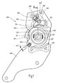
- Fig. 1
- eine Seitenansicht des Ausführungsbeispiels in einer Gebrauchsstellung,
- Fig. 2
- eine Ansicht entsprechend Fig. 1 in der freigeschwenkten Stellung,
- Fig. 3
- einen Schnitt entlang der Linie III-III in Fig. 1,
- Fig. 4
- eine schematische Seitenansicht eines Fahrzeugsitzes, und
- Fig. 5
- eine vergrößerte Darstellung des Sicherungsblechs.
- 201
- Fahrzeugsitz
- 202
- Lehne
- 203
- Sitzteil
- 205
- Beschlag
- 207
- Handrad
- 208
- Handhebel
- 209
- Taumelunterteil
- 211
- Taumeloberteil
- 214
- Freischwenkteil
- 215
- Kragenzug
- 216
- Lagerbolzen
- 224
- Entriegelungsbolzen
- 226
- Kulisse
- 232
- Sicherungsklinke
- 233
- Steuerkurve
- 235
- Sicherungsring, Sicherungselement
- 237
- Doppelflanschring
- 245
- Aufnahme
- 247
- Vorsprung
- 249
- Adapter
- 251
- Absatz
- 260
- Sperrblech, Sperrelement
- 260'
- Sperrgeometrie
- 262
- Öffnung
- 262'
- Entriegelungsgeometrie
- 264
- Sperrnocken
- 264'
- Innenecke
Claims (9)
- Beschlag für einen Fahrzeugsitz, insbesondere für einen Kraftfahrzeugsitz, mit einem sitzteilstrukturfesten Unterteil (209), einem relativ zum Unterteil (209) verdrehbaren Oberteil (211) für die Neigungseinstellung der Lehne (202) des Fahrzeugsitzes (201) zwischen mehreren Gebrauchsstellungen, und einem lehnenstrukturfesten, mit dem Oberteil (211) verriegelbaren und für ein zentrisches Freischwenken der Lehne (202) relativ zum Oberteil (211) verschwenkbaren Freischwenkteil (214), welches zur Sicherung der freigeschwenkten Stellung der Lehne (202) am Unterteil (209) festlegbar ist, wobei am Freischwenkteil (214) eine schwenkbare Sicherungsklinke (232) gelagert ist, welche zum Festlegen des Freischwenkteils (214) in der freigeschwenkten Stellung mit einem am Unterteil (209) abgestützten Sicherungselement (235) zusammenwirkt, wobei die Sicherungsklinke (232) in der freigeschwenkten Stellung durch ein Sperrelement (260) gegen ein Öffnen gesichert ist, dadurch gekennzeichnet, daß das Sperrelement (260) zum Sichern der Sicherungsklinke (232) mit einem freischwenkteilfesten Spermocken (264) zusammenwirkt.
- Beschlag nach Anspruch 1, dadurch gekennzeichnet, daß zum Lösen der Verriegelung zwischen Freischwenkteil (214) und Oberteil (211) ein in der Schwenkebene des Freischwenkteils (214) beweglicher Entriegelungsbolzen (224) vorgesehen ist.
- Beschlag nach Anspruch 2, dadurch gekennzeichnet, daß das Sperrelement (260) an den Entriegelungsbolzen (224) gekoppelt ist.
- Beschlag nach Anspruch 2 oder 3, dadurch gekennzeichnet, daß das Sperrelement (260) eine Entriegelungsgeometrie (262') aufweist, an welche der Entriegelungsbolzen (224) zu Beginn der Rückkehr von der freigeschwenkten Stellung in die Ausgangsstellung in Anlage gelangt.
- Beschlag nach Anspruch 4, dadurch gekennzeichnet, daß die Entriegelungsgeometrie (262') bei Anlage des Entriegelungsbolzens (224) wenigstens teilweise schräg zur Bewegungsrichtung des Entriegelungsbolzens (224) verläuft.
- Beschlag nach Anspruch 5, dadurch gekennzeichnet, daß der Entriegelungsbolzen (224) bei Anlage an die Entriegelungsgeometrie (262') das Sperrelement (260) vom Sperrnocken (264) abzieht.
- Beschlag nach einem der Ansprüche 1 bis 6, dadurch gekennzeichnet, daß das Sicherungselement (235) einen Absatz (251) zwischen einem vorderen, radial weiter innen gelegenen Abschnitt des Sicherungselementes (235) und einem hinteren, radial weiter außen gelegenen Abschnitt des Sicherungselementes (235) aufweist, wobei in der freigeschwenkten Stellung die, Sicherungsklinke (232) den Absatz (251) hintergreift.
- Beschlag nach einem der Ansprüche 1 bis 7, dadurch gekennzeichnet, daß das Sicherungselement (235) über eine Schlitz-Zapfen-Führung (245, 247) am Unterteil (209) abgestützt ist.
- Fahrzeugsitz (201) mit einer Lehne (202), gekennzeichnet durch einen Beschlag (205) nach einem der Ansprüche 1 bis 8 zur Neigungseinstellung und zum Freischwenken der Lehne (202).
Applications Claiming Priority (2)
| Application Number | Priority Date | Filing Date | Title |
|---|---|---|---|
| DE10206303 | 2002-02-11 | ||
| DE10206303A DE10206303A1 (de) | 2002-02-11 | 2002-02-11 | Beschlag für einen Fahr zeugsitz |
Publications (3)
| Publication Number | Publication Date |
|---|---|
| EP1334866A2 EP1334866A2 (de) | 2003-08-13 |
| EP1334866A3 EP1334866A3 (de) | 2003-11-05 |
| EP1334866B1 true EP1334866B1 (de) | 2004-10-27 |
Family
ID=27588575
Family Applications (1)
| Application Number | Title | Priority Date | Filing Date |
|---|---|---|---|
| EP03002350A Expired - Lifetime EP1334866B1 (de) | 2002-02-11 | 2003-02-04 | Beschlag für einen Fahrzeugsitz |
Country Status (2)
| Country | Link |
|---|---|
| EP (1) | EP1334866B1 (de) |
| DE (2) | DE10206303A1 (de) |
Cited By (4)
| Publication number | Priority date | Publication date | Assignee | Title |
|---|---|---|---|---|
| US7264566B2 (en) | 2003-02-11 | 2007-09-04 | Keiper Gmbh & Co. Kg | Geared fitting for a vehicle seat |
| US7547069B2 (en) | 2005-12-02 | 2009-06-16 | Keiper Gmbh & Co. Kg | Vehicle seat, particularly a motor vehicle seat |
| US7726741B2 (en) | 2004-12-01 | 2010-06-01 | Keiper Gmbh & Co. Kg | Longitudinal adjuster for a vehicle seat |
| CN101314331B (zh) * | 2007-05-31 | 2012-08-22 | 李尔公司 | 交通工具座椅 |
Families Citing this family (23)
| Publication number | Priority date | Publication date | Assignee | Title |
|---|---|---|---|---|
| DE10305408B3 (de) * | 2003-02-11 | 2004-07-29 | Keiper Gmbh & Co. Kg | Verfahren zur Verbindung zweier Bauteile eines Beschlags |
| FR2876560B1 (fr) * | 2004-10-19 | 2007-01-12 | Antolin Grupo Ing Sa | Dispositif d'articulation d'un siege |
| DE102005040466B4 (de) * | 2005-08-26 | 2011-04-07 | Keiper Gmbh & Co. Kg | Beschlag für einen Fahrzeugsitz |
| DE102005040629B4 (de) * | 2005-08-27 | 2009-02-26 | Keiper Gmbh & Co.Kg | Beschlag für einen Fahrzeugsitz |
| DE102006044490B4 (de) * | 2006-01-24 | 2008-08-28 | Keiper Gmbh & Co.Kg | Beschlag für einen Fahrzeugsitz |
| DE102006003241B4 (de) * | 2006-01-24 | 2011-05-19 | Keiper Gmbh & Co. Kg | Beschlag für einen Fahrzeugsitz |
| DE102006044489B4 (de) * | 2006-01-24 | 2014-07-10 | Keiper Gmbh & Co. Kg | Beschlag für einen Fahrzeugsitz sowie Fahrzeugsitz mit einem solchen Beschlag |
| DE102006003243B4 (de) * | 2006-01-24 | 2011-04-14 | Keiper Gmbh & Co. Kg | Beschlag für einen Fahrzeugsitz |
| DE102006045576B4 (de) * | 2006-09-25 | 2009-04-02 | Johnson Controls Gmbh | Schwenkbarer Fahrzeugsitz mit einem Rastmittel zur Erzeugung eines manuell überwindbaren Widerstandes |
| DE102006058891B4 (de) | 2006-12-04 | 2009-04-09 | Progress-Werk Oberkirch Ag | Vorrichtung zum Verriegeln eines Fahrzeugsitzes |
| DE102007011998B4 (de) * | 2007-03-09 | 2013-08-01 | Johnson Controls Gmbh | Fahrzeugsitz mit einem Beschlag zur Neigungsverstellung und zum Freischwenken einer Lehne |
| JP5520611B2 (ja) * | 2007-03-09 | 2014-06-11 | ジョンソン・コントロールズ・ゲー・エム・ベー・ハー | タンブルリクライナを有する車両シート |
| DE102008008935B3 (de) | 2008-02-08 | 2009-09-03 | Keiper Gmbh & Co. Kg | Beschlag für einen Fahrzeugsitz |
| DE102008038581A1 (de) | 2008-08-18 | 2010-02-25 | Keiper Gmbh & Co. Kg | Anordnung für einen Fahrzeugsitz |
| DE202008011680U1 (de) * | 2008-08-28 | 2008-11-06 | Keiper Gmbh & Co.Kg | Beschlag für einen Fahrzeugsitz |
| DE102009022979B3 (de) * | 2009-02-19 | 2010-08-19 | Keiper Gmbh & Co. Kg | Längseinsteller für einen Fahrzeugsitz |
| DE102009037819B4 (de) | 2009-08-12 | 2024-07-18 | Keiper Seating Mechanisms Co., Ltd. | Beschlag für einen Fahrzeugsitz sowie Fahrzeugsitz mit diesem Beschlag |
| FR2975052B1 (fr) | 2011-05-11 | 2014-02-07 | Faurecia Sieges Automobile | Ensemble d'articulation pour siege de vehicule et siege de vehicule comprenant l'ensemble d'articulation |
| GB2492783B (en) * | 2011-07-12 | 2018-06-06 | Bentley Motors Ltd | Frame for vehicle seat with a detent mechanism |
| DE102014206537B4 (de) * | 2014-02-07 | 2017-05-11 | Adient Luxembourg Holding S.à.r.l. | Fahrzeugsitz, insbesondere kraftfahrzeugsitz |
| DE102015205679A1 (de) | 2014-09-16 | 2016-03-31 | Johnson Controls Components Gmbh & Co. Kg | Fahrzeugsitz, insbesondere kraftfahrzeugsitz, und verfahren zur montage eines fahrzeugsitzes |
| CN107962987B (zh) * | 2017-12-12 | 2023-07-21 | 广州汽车集团零部件有限公司 | 一种汽车座椅靠背调节结构 |
| CN109606212B (zh) * | 2019-01-21 | 2024-08-02 | 广西双英集团股份有限公司 | 一种座椅定点保持机构 |
Family Cites Families (4)
| Publication number | Priority date | Publication date | Assignee | Title |
|---|---|---|---|---|
| FR2494574A1 (fr) * | 1980-11-26 | 1982-05-28 | Renault | Mecanisme de reglage et de commande d'inclinaison d'un dossier de siege |
| DE3828659A1 (de) * | 1987-09-11 | 1989-03-23 | Volkswagen Ag | Gelenkbeschlag fuer einen fahrzeugsitz mit verstellbarer rueckenlehne |
| DE19913432C2 (de) * | 1999-03-25 | 2003-02-13 | Keiper Recaro Gmbh Co | Fahrzeugsitz mit freischwenkbarer Rückenlehne |
| GB2358132B (en) * | 2000-01-14 | 2003-12-31 | Autoliv Dev | A recliner mechanism for a vehicle seat |
-
2002
- 2002-02-11 DE DE10206303A patent/DE10206303A1/de not_active Withdrawn
-
2003
- 2003-02-04 EP EP03002350A patent/EP1334866B1/de not_active Expired - Lifetime
- 2003-02-04 DE DE50300123T patent/DE50300123D1/de not_active Expired - Lifetime
Cited By (4)
| Publication number | Priority date | Publication date | Assignee | Title |
|---|---|---|---|---|
| US7264566B2 (en) | 2003-02-11 | 2007-09-04 | Keiper Gmbh & Co. Kg | Geared fitting for a vehicle seat |
| US7726741B2 (en) | 2004-12-01 | 2010-06-01 | Keiper Gmbh & Co. Kg | Longitudinal adjuster for a vehicle seat |
| US7547069B2 (en) | 2005-12-02 | 2009-06-16 | Keiper Gmbh & Co. Kg | Vehicle seat, particularly a motor vehicle seat |
| CN101314331B (zh) * | 2007-05-31 | 2012-08-22 | 李尔公司 | 交通工具座椅 |
Also Published As
| Publication number | Publication date |
|---|---|
| DE10206303A1 (de) | 2003-08-21 |
| EP1334866A2 (de) | 2003-08-13 |
| DE50300123D1 (de) | 2004-12-02 |
| EP1334866A3 (de) | 2003-11-05 |
Similar Documents
| Publication | Publication Date | Title |
|---|---|---|
| EP1334866A2 (de) | Beschlag für einen Fahrzeugsitz | |
| EP2240342B1 (de) | Beschlag für einen fahrzeugsitz | |
| EP2240341B1 (de) | Verriegelungsvorrichtung, insbesondere für einen fahrzeugsitz | |
| EP1976723B1 (de) | Beschlag für einen fahrzeugsitz | |
| EP2684737A1 (de) | Fahrzeugsitz mit einem Taumelrecliner | |
| DE102006047991B4 (de) | Aufbau eines verstellbaren Sitzes | |
| DE102006003243B4 (de) | Beschlag für einen Fahrzeugsitz | |
| DE102006001530B4 (de) | Kraftfahrzeugsitz mit Easy-Entry-Funktion | |
| EP1334867B1 (de) | Beschlag für einen Fahrzeugsitz | |
| EP2221210B1 (de) | Beschlag für einen Fahrzeugsitz | |
| DE10206304B4 (de) | Beschlag für einen Fahrzeugsitz | |
| WO2010022844A1 (de) | Beschlag für einen fahrzeugsitz | |
| EP2544918B1 (de) | Beschlag für einen fahrzeugsitz | |
| DE102007030545B3 (de) | Beschlag für einen Fahrzeugsitz | |
| DE10121020A1 (de) | Beschlag für einen Fahrzeugsitz | |
| DE102005040629B4 (de) | Beschlag für einen Fahrzeugsitz | |
| DE19921821A1 (de) | Fahrzeugsitz, insbesondere Kraftfahrzeugsitz | |
| DE102009037819A1 (de) | Beschlag für einen Fahrzeugsitz | |
| DE20122218U1 (de) | Beschlag für einen Fahrzeugsitz | |
| DE19622157A1 (de) | Kraftfahrzeugsitz mit Neigungsverstellvorrichtung für die Rückenlehne und Zusatzsicherungseinrichtung | |
| DE102013221931B4 (de) | Beschlag und Fahrzeugsitz mit einem Beschlag | |
| DE102005040466B4 (de) | Beschlag für einen Fahrzeugsitz | |
| DE202006005049U1 (de) | Beschlag für einen Fahrzeugsitz | |
| DE202006015871U1 (de) | Beschlag für einen Fahrzeugsitz | |
| EP3254891B1 (de) | Lehnenkonstruktion |
Legal Events
| Date | Code | Title | Description |
|---|---|---|---|
| PUAI | Public reference made under article 153(3) epc to a published international application that has entered the european phase |
Free format text: ORIGINAL CODE: 0009012 |
|
| AK | Designated contracting states |
Designated state(s): AT BE BG CH CY CZ DE DK EE ES FI FR GB GR HU IE IT LI LU MC NL PT SE SI SK TR |
|
| AX | Request for extension of the european patent |
Extension state: AL LT LV MK RO |
|
| PUAL | Search report despatched |
Free format text: ORIGINAL CODE: 0009013 |
|
| AK | Designated contracting states |
Kind code of ref document: A3 Designated state(s): AT BE BG CH CY CZ DE DK EE ES FI FR GB GR HU IE IT LI LU MC NL PT SE SI SK TR |
|
| AX | Request for extension of the european patent |
Extension state: AL LT LV MK RO |
|
| 17P | Request for examination filed |
Effective date: 20031205 |
|
| 17Q | First examination report despatched |
Effective date: 20040218 |
|
| GRAP | Despatch of communication of intention to grant a patent |
Free format text: ORIGINAL CODE: EPIDOSNIGR1 |
|
| AKX | Designation fees paid |
Designated state(s): DE FR GB IT |
|
| GRAS | Grant fee paid |
Free format text: ORIGINAL CODE: EPIDOSNIGR3 |
|
| GRAA | (expected) grant |
Free format text: ORIGINAL CODE: 0009210 |
|
| AK | Designated contracting states |
Kind code of ref document: B1 Designated state(s): DE FR GB IT |
|
| REG | Reference to a national code |
Ref country code: GB Ref legal event code: FG4D Free format text: NOT ENGLISH |
|
| REG | Reference to a national code |
Ref country code: IE Ref legal event code: FG4D Free format text: GERMAN |
|
| REF | Corresponds to: |
Ref document number: 50300123 Country of ref document: DE Date of ref document: 20041202 Kind code of ref document: P |
|
| GBT | Gb: translation of ep patent filed (gb section 77(6)(a)/1977) |
Effective date: 20050214 |
|
| REG | Reference to a national code |
Ref country code: IE Ref legal event code: FD4D |
|
| ET | Fr: translation filed | ||
| PLBE | No opposition filed within time limit |
Free format text: ORIGINAL CODE: 0009261 |
|
| STAA | Information on the status of an ep patent application or granted ep patent |
Free format text: STATUS: NO OPPOSITION FILED WITHIN TIME LIMIT |
|
| 26N | No opposition filed |
Effective date: 20050728 |
|
| PGFP | Annual fee paid to national office [announced via postgrant information from national office to epo] |
Ref country code: IT Payment date: 20110528 Year of fee payment: 9 |
|
| REG | Reference to a national code |
Ref country code: DE Ref legal event code: R082 Ref document number: 50300123 Country of ref document: DE |
|
| PG25 | Lapsed in a contracting state [announced via postgrant information from national office to epo] |
Ref country code: IT Free format text: LAPSE BECAUSE OF NON-PAYMENT OF DUE FEES Effective date: 20120204 |
|
| PGFP | Annual fee paid to national office [announced via postgrant information from national office to epo] |
Ref country code: GB Payment date: 20140218 Year of fee payment: 12 |
|
| REG | Reference to a national code |
Ref country code: DE Ref legal event code: R081 Ref document number: 50300123 Country of ref document: DE Owner name: JOHNSON CONTROLS COMPONENTS GMBH & CO. KG, DE Free format text: FORMER OWNER: KEIPER GMBH & CO. KG, 67657 KAISERSLAUTERN, DE Effective date: 20140710 Ref country code: DE Ref legal event code: R081 Ref document number: 50300123 Country of ref document: DE Owner name: ADIENT LUXEMBOURG HOLDING S.A.R.L., LU Free format text: FORMER OWNER: KEIPER GMBH & CO. KG, 67657 KAISERSLAUTERN, DE Effective date: 20140710 Ref country code: DE Ref legal event code: R081 Ref document number: 50300123 Country of ref document: DE Owner name: ADIENT LUXEMBOURG HOLDING S.A R.L., LU Free format text: FORMER OWNER: KEIPER GMBH & CO. KG, 67657 KAISERSLAUTERN, DE Effective date: 20140710 |
|
| GBPC | Gb: european patent ceased through non-payment of renewal fee |
Effective date: 20150204 |
|
| PG25 | Lapsed in a contracting state [announced via postgrant information from national office to epo] |
Ref country code: GB Free format text: LAPSE BECAUSE OF NON-PAYMENT OF DUE FEES Effective date: 20150204 |
|
| REG | Reference to a national code |
Ref country code: FR Ref legal event code: PLFP Year of fee payment: 14 |
|
| REG | Reference to a national code |
Ref country code: DE Ref legal event code: R081 Ref document number: 50300123 Country of ref document: DE Owner name: ADIENT US LLC, PLYMOUTH, US Free format text: FORMER OWNER: JOHNSON CONTROLS COMPONENTS GMBH & CO. KG, 67657 KAISERSLAUTERN, DE Ref country code: DE Ref legal event code: R081 Ref document number: 50300123 Country of ref document: DE Owner name: ADIENT LUXEMBOURG HOLDING S.A.R.L., LU Free format text: FORMER OWNER: JOHNSON CONTROLS COMPONENTS GMBH & CO. KG, 67657 KAISERSLAUTERN, DE Ref country code: DE Ref legal event code: R081 Ref document number: 50300123 Country of ref document: DE Owner name: ADIENT LUXEMBOURG HOLDING S.A R.L., LU Free format text: FORMER OWNER: JOHNSON CONTROLS COMPONENTS GMBH & CO. KG, 67657 KAISERSLAUTERN, DE |
|
| REG | Reference to a national code |
Ref country code: FR Ref legal event code: PLFP Year of fee payment: 15 |
|
| REG | Reference to a national code |
Ref country code: FR Ref legal event code: PLFP Year of fee payment: 16 |
|
| REG | Reference to a national code |
Ref country code: DE Ref legal event code: R084 Ref document number: 50300123 Country of ref document: DE |
|
| REG | Reference to a national code |
Ref country code: DE Ref legal event code: R081 Ref document number: 50300123 Country of ref document: DE Owner name: ADIENT US LLC, PLYMOUTH, US Free format text: FORMER OWNER: ADIENT LUXEMBOURG HOLDING S.A.R.L., LUXEMBOURG, LU Ref country code: DE Ref legal event code: R081 Ref document number: 50300123 Country of ref document: DE Owner name: ADIENT LUXEMBOURG HOLDING S.A R.L., LU Free format text: FORMER OWNER: ADIENT LUXEMBOURG HOLDING S.A.R.L., LUXEMBOURG, LU |
|
| PGFP | Annual fee paid to national office [announced via postgrant information from national office to epo] |
Ref country code: DE Payment date: 20220225 Year of fee payment: 20 |
|
| REG | Reference to a national code |
Ref country code: DE Ref legal event code: R082 Ref document number: 50300123 Country of ref document: DE Representative=s name: LIEDHEGENER, RALF, DIPL.-ING., DE |
|
| PGFP | Annual fee paid to national office [announced via postgrant information from national office to epo] |
Ref country code: FR Payment date: 20220223 Year of fee payment: 20 |
|
| REG | Reference to a national code |
Ref country code: DE Ref legal event code: R081 Ref document number: 50300123 Country of ref document: DE Owner name: ADIENT US LLC, PLYMOUTH, US Free format text: FORMER OWNER: ADIENT LUXEMBOURG HOLDING S.A R.L., LUXEMBOURG, LU |
|
| REG | Reference to a national code |
Ref country code: DE Ref legal event code: R071 Ref document number: 50300123 Country of ref document: DE |