EP1334020B1 - Verfahren zur ermittlung der soll-drehgeschwindigkeit eines elektromotors für eine hydraulikpumpe und lenkeinrichtung für ein fahrzeug - Google Patents
Verfahren zur ermittlung der soll-drehgeschwindigkeit eines elektromotors für eine hydraulikpumpe und lenkeinrichtung für ein fahrzeug Download PDFInfo
- Publication number
- EP1334020B1 EP1334020B1 EP01996489A EP01996489A EP1334020B1 EP 1334020 B1 EP1334020 B1 EP 1334020B1 EP 01996489 A EP01996489 A EP 01996489A EP 01996489 A EP01996489 A EP 01996489A EP 1334020 B1 EP1334020 B1 EP 1334020B1
- Authority
- EP
- European Patent Office
- Prior art keywords
- vehicle
- hydraulic pump
- electric motor
- mot
- speed
- Prior art date
- Legal status (The legal status is an assumption and is not a legal conclusion. Google has not performed a legal analysis and makes no representation as to the accuracy of the status listed.)
- Expired - Lifetime
Links
- 230000005540 biological transmission Effects 0.000 claims abstract description 15
- 230000003247 decreasing effect Effects 0.000 claims 1
- 230000007423 decrease Effects 0.000 abstract 1
- 230000001419 dependent effect Effects 0.000 description 3
- 238000005265 energy consumption Methods 0.000 description 3
- 238000011161 development Methods 0.000 description 2
- 230000018109 developmental process Effects 0.000 description 2
- 238000010586 diagram Methods 0.000 description 2
- 230000000694 effects Effects 0.000 description 1
- 230000005284 excitation Effects 0.000 description 1
Images

Classifications
-
- B—PERFORMING OPERATIONS; TRANSPORTING
- B62—LAND VEHICLES FOR TRAVELLING OTHERWISE THAN ON RAILS
- B62D—MOTOR VEHICLES; TRAILERS
- B62D5/00—Power-assisted or power-driven steering
- B62D5/06—Power-assisted or power-driven steering fluid, i.e. using a pressurised fluid for most or all the force required for steering a vehicle
- B62D5/065—Power-assisted or power-driven steering fluid, i.e. using a pressurised fluid for most or all the force required for steering a vehicle characterised by specially adapted means for varying pressurised fluid supply based on need, e.g. on-demand, variable assist
Definitions
- Electrohydraulic pressure supply units are essentially known from stationary mobile hydraulics. Similar concepts are also known for applications in steering systems, for example from DE 197 35 647 C1, DE 198 20 381 A1, DE 198 18 139 A1.
- the invention is based on the type as in the independent claim 1 or 2 and described in DE 39 20 862 A1.
- preferred Applications are hydraulic steering devices with a control valve with open center.
- a generic steering device causes a low Energy consumption when the speed (rotational speed) of the electric motor is reduced at higher vehicle speeds.
- EP 673 328 B1 and the overall efficiency EP 741 068 A2.
- New in conjunction with other features is the use of the current one Motor current with appropriate algorithms as additional control of the Control unit.
- the motor current behaves in the quasi-static state proportional to hydraulic system pressure and steering application to Steering torque).
- a rule principle is created by the invention, that for each control variable (which is proportional to, for example Steering speed, motor current, constant component) by different Algorithms determines an output portion (e.g., speed).
- a weighting function e.g., speed function
- an electric motor E drives a hydraulic pump P, which in a Vehicle, for example, the working cylinder of a power steering over a Supply control valve.
- the motor voltage is from a motor controller PCU controlled, which derives its supply voltage from a battery B.
- a motor controller PCU controlled, which derives its supply voltage from a battery B.
- a pulse width modulator as controllable Voltage transformers included.
- the motor controller PCU also has commutator means on.
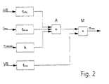
- control variables a) to c) are fed in the control unit (ECU) via a respective transmission element f (HS) , f (Imot) , k to an adder A which adds the output components coming from the transmission elements .
- the output of the adder A is connected to a first input of a multiplier M, which supplies the setpoint n Mot for the control unit (PCU in FIG. 1).
- a second input of the multiplier M is fed via a fourth transmission element f (VS) from a fourth control quantity which is proportional to the vehicle speed VS.
- the first transmission element f (HS) and the third transmission element k can, for example, have a linear transmission function, ie the steering angle speed HS or the standby speed n to be determined once by the hydraulic pump P multiply only by a constant factor, in particular 1.
- the second transmission element f (Imot) preferably contains a low-pass filter with a time constant of, for example, 0.15 s.
- the fourth transmission element f has a transfer function by which a falling signal is supplied to the second input of the motor controller (M) with increasing vehicle speed (VS).
- this signal has a slightly falling tendency between 0 and 50 km / h, which increases between 50 and 100 km / h and which increases again from 100 km / h. It is therefore a multiple kinked characteristic curve, which is used in a simplified manner instead of a continuous characteristic curve.
- the invention is not only in steering systems, but also in other hydraulic applications in motor vehicles, e.g. chassis systems applicable.
Landscapes
- Engineering & Computer Science (AREA)
- Chemical & Material Sciences (AREA)
- Combustion & Propulsion (AREA)
- Transportation (AREA)
- Mechanical Engineering (AREA)
- Steering Control In Accordance With Driving Conditions (AREA)
- Power Steering Mechanism (AREA)
Description
Ähnliche Konzeptionen sind auch für Anwendungen in Lenksystemen bekannt, beispielsweise aus DE 197 35 647 C1, DE 198 20 381 A1, DE 198 18 139 A1.
- eine Absenkung der Energieaufnahme im "Stand-by-Betrieb",
- ein Absenken der Energieaufnahme im Fahrzyklus,
- eine Absenkung des Temperaturniveaus,
- ein komfortables Lenkverhalten (geschwindigkeitsabhängige Lenkunterstützung),
- eine rückwirkungsfreie Drehzahlregulierung der Hydraulikpumpe.
- Figur 1:
- ein Blockschaltbild einer Steuereinrichtung für einen Elektromotor, der eine Hydraulikpumpe antreibt,
- Figur 2:
- ein Blockschaltbild des in Figur 1 enthaltenen Steuergerätes ECU.
Claims (4)
- Verfahren zur Ermittlung der Soll-Drehgeschwindigkeit (nMot) eines Elektromotors (E), der eine Hydraulikpumpe (P) in einem Fahrzeug antreibt und der in Abhängigkeit von der Fahrzeuggeschwindigkeit (VS) gesteuert ist,
dadurch gekennzeichnet, dass
wenigstens drei Steuergrößen, die proportional sind zu folgenden Messgrößen:jeweils vor oder nach Beeinflussung durch zugehörige Übertragungsglieder (f(HS), f(Imot), k) mit einer Größe multipliziert werden, die mit steigender Fahrzeuggeschwindigkeit (VS) abnimmt.a) Lenkwinkelgeschwindigkeit (HS) des Fahrzeugs,b) Stand-by-Drehgeschwindigkeit (nstandby) der Hydraulikpumpe (P)c) Eingangsstrom (IMot) des Elektromotors (E), - Lenkeinrichtung für ein Fahrzeug, mit einer Hydraulikpumpe (P), die von einem Elektromotor (E) angetrieben ist, der in Abhängigkeit von der Fahrzeuggeschwindigkeit (VS) gesteuert ist,
gekennzeichnet durch folgende Merkmale:dem Elektromotor (E) ist ein Motorregler (PCU) vorgeschaltet, dem ein Sollwert (nMot) für die Motordrehgeschwindigkeit vorgegeben ist und der dementsprechend die Versorgungsspannung des Elektromotors (E) steuert,der Sollwert (nMot) wird von einem Steuergerät (ECU) geliefert, dem wenigstens drei Steuergrößen zugeführt sind, die proportional sind zu folgenden Messgrößen:a) Lenkwinkelgeschwindigkeit (HS) des Fahrzeugs,b) Stand-by-Drehgeschwindigkeit (nstandby) der Hydraulikpumpe (P),c) Eingangsstrom (IMot) des Elektromotors (E),diese drei Steuergrößen sind im Steuergerät (ECU) über jeweils ein Übertragungsglied (f(HS), f(Imot), k) einem Addierer (A) zugeführt,der Ausgang des Addierers (A) ist mit einem ersten Eingang eines Multiplizierers (M) verbunden, der den Sollwert (nMot) liefert,ein zweiter Eingang des Multiplizierers (M) ist über ein viertes Übertragungsglied (f(VS)) von einer vierten Steuergröße gespeist, die der Fahrzeuggeschwindigkeit (VS) proportional ist. - Lenkeinrichtung nach Anspruch 2, dadurch gekennzeichnet, dass das Übertragungsglied (f(Imot)) für die Steuergröße, welche den Eingangsstrom (IMot) des Elektromotors (E) repräsentiert, einen Tiefpass aufweist.
- Lenkeinrichtung nach Anspruch 2 oder 3, dadurch gekennzeichnet, dass das vierte Übertragungsglied (f(VS)) eine Übertragungsfunktion aufweist, durch welche dem zweiten Eingang des Motorreglers (M) mit steigender Fahrzeuggeschwindigkeit (VS) ein abfallendes Signal zugeführt wird.
Applications Claiming Priority (3)
| Application Number | Priority Date | Filing Date | Title |
|---|---|---|---|
| DE10056588 | 2000-11-15 | ||
| DE10056588A DE10056588A1 (de) | 2000-11-15 | 2000-11-15 | Verfahren zur Ermittlung der Soll-Drehgeschwindigkeit eines Elektromotors für eine Hydraulikpumpe und Lenkeinrichtung für ein Fahrzeug |
| PCT/EP2001/012845 WO2002040338A1 (de) | 2000-11-15 | 2001-11-07 | Verfahren zur ermittlung der soll-drehgeschwindigkeit eines elektromotors für eine hydraulikpumpe und lenkeinrichtung für ein fahrzeug |
Publications (2)
| Publication Number | Publication Date |
|---|---|
| EP1334020A1 EP1334020A1 (de) | 2003-08-13 |
| EP1334020B1 true EP1334020B1 (de) | 2005-01-26 |
Family
ID=7663377
Family Applications (1)
| Application Number | Title | Priority Date | Filing Date |
|---|---|---|---|
| EP01996489A Expired - Lifetime EP1334020B1 (de) | 2000-11-15 | 2001-11-07 | Verfahren zur ermittlung der soll-drehgeschwindigkeit eines elektromotors für eine hydraulikpumpe und lenkeinrichtung für ein fahrzeug |
Country Status (4)
| Country | Link |
|---|---|
| EP (1) | EP1334020B1 (de) |
| AT (1) | ATE287818T1 (de) |
| DE (2) | DE10056588A1 (de) |
| WO (1) | WO2002040338A1 (de) |
Families Citing this family (4)
| Publication number | Priority date | Publication date | Assignee | Title |
|---|---|---|---|---|
| DE102004028826A1 (de) * | 2004-06-15 | 2006-01-05 | Zf Lenksysteme Gmbh | Servounterstütztes Lenksystem eines Kraftfahrzeugs |
| DE102006017010B4 (de) * | 2006-04-11 | 2015-07-23 | Trw Automotive Gmbh | Verfahren zur Steuerung einer Servolenkung sowie Servolenkung |
| FR2935670B1 (fr) * | 2008-09-11 | 2011-08-05 | Jtekt Hpi | Procede de strategie de reduction de la consommation d'energie d'un vehicule automobile. |
| CN113187782B (zh) * | 2021-05-07 | 2022-08-02 | 潍柴动力股份有限公司 | 一种闭式液压系统的控制方法、装置、设备及存储介质 |
Family Cites Families (6)
| Publication number | Priority date | Publication date | Assignee | Title |
|---|---|---|---|---|
| JPS58156857A (ja) * | 1982-03-15 | 1983-09-17 | Tokai T R W Kk | 回転検出装置 |
| DE3920862A1 (de) * | 1989-06-26 | 1991-01-03 | Teves Gmbh Alfred | Hilfskraftlenkung fuer kraftfahrzeuge |
| JP2643041B2 (ja) * | 1991-09-18 | 1997-08-20 | 三菱電機株式会社 | 電動パワーステアリング制御方法 |
| FR2688183B1 (fr) * | 1992-03-04 | 1997-06-13 | Ecia Equip Composants Ind Auto | Dispositif d'assistance de direction notamment de vehicule automobile. |
| JP3506810B2 (ja) * | 1995-06-19 | 2004-03-15 | ユニシア ジェーケーシー ステアリングシステム株式会社 | 電動ポンプ式動力舵取装置 |
| US6092618A (en) * | 1997-10-31 | 2000-07-25 | General Motors Corporation | Electro-hydraulic power steering control with fluid temperature and motor speed compensation of power steering load signal |
-
2000
- 2000-11-15 DE DE10056588A patent/DE10056588A1/de not_active Withdrawn
-
2001
- 2001-11-07 DE DE50105218T patent/DE50105218D1/de not_active Expired - Lifetime
- 2001-11-07 WO PCT/EP2001/012845 patent/WO2002040338A1/de not_active Ceased
- 2001-11-07 AT AT01996489T patent/ATE287818T1/de not_active IP Right Cessation
- 2001-11-07 EP EP01996489A patent/EP1334020B1/de not_active Expired - Lifetime
Also Published As
| Publication number | Publication date |
|---|---|
| DE50105218D1 (de) | 2005-03-03 |
| EP1334020A1 (de) | 2003-08-13 |
| ATE287818T1 (de) | 2005-02-15 |
| WO2002040338A1 (de) | 2002-05-23 |
| DE10056588A1 (de) | 2002-06-20 |
Similar Documents
| Publication | Publication Date | Title |
|---|---|---|
| EP1268259B1 (de) | Servounterstütztes lenksystem eines kraftfahrzeugs | |
| DE19919797B4 (de) | Elektrisches Servolenkungssystem | |
| DE69622356T2 (de) | Lenkungssteuerung mit Lenkdrehmoment-Hysterese | |
| DE69932223T2 (de) | Lenkungssteuerverfahren für eine Servolenkung mit variabler Unterstützung | |
| DE10142154B4 (de) | Steuereinheit für elektrische Servolenkung | |
| DE19920975A1 (de) | Elektrisches Servolenksystem | |
| DE19919374A1 (de) | Mit variabler Kraft unterstützende Servolenkungsvorrichtung | |
| DE60035825T2 (de) | Gleichstrommotorantriebseinheit und Servolenksteuerungseinrichtung | |
| EP0803427B1 (de) | Fahrzeuglenkung | |
| DE10138540A1 (de) | Steuereinheit für elektrische Hilfskraftlenkvorrichtung | |
| DE102007038628B4 (de) | Fahrzeuglenkungsvorrichtung | |
| DE112015003212T5 (de) | Elektrische Servolenkvorrichtung und elektrisches Servolenksystem | |
| DE60314496T2 (de) | Steuervorrichtung für elektrische servolenkvorrichtung | |
| DE19733096C2 (de) | Verfahren und Anordnung zur Regelung einer Hilfskrafteinrichtung in einem Kraftfahrzeug | |
| EP1521701B1 (de) | Verfahren zum lenken eines fahrzeugs mit einer überlagerungslenkung | |
| DE10325484A1 (de) | Verfahren zum Lenken eines Fahrzeugs mit einer Überlagerungslenkung | |
| DE19820381A1 (de) | Verfahren zur Beeinflussung der Ventilkennlinie | |
| WO2006087336A1 (de) | Verfahren zum lenken eines fahrzuegs und fahrzeuglenkung | |
| DE10056588A1 (de) | Verfahren zur Ermittlung der Soll-Drehgeschwindigkeit eines Elektromotors für eine Hydraulikpumpe und Lenkeinrichtung für ein Fahrzeug | |
| DE102021209569A1 (de) | Elektronische Steuereinheit, Hydrauliksystem und Verfahren zur Steuerung eines Hydrauliksvstems | |
| EP1631484B1 (de) | Verfahren zur steuerung eines elektrischen pumpenantriebsmotors einer servolenkvorrichtung | |
| DE2838417A1 (de) | Hydraulische servolenkung | |
| EP1826054A2 (de) | Verfahren sowie Vorrichtung zur Regelung eines hydraulischen Antriebssystems | |
| DE10328752A1 (de) | Verfahren zum Lenken eines Fahrzeugs mit einer Überlagerungslenkung | |
| DE112005000670B4 (de) | Elektrische Servolenkungsvorrichtung und Verfahren zum Steuern einer elektrischen Servolenkvorrichtung |
Legal Events
| Date | Code | Title | Description |
|---|---|---|---|
| PUAI | Public reference made under article 153(3) epc to a published international application that has entered the european phase |
Free format text: ORIGINAL CODE: 0009012 |
|
| 17P | Request for examination filed |
Effective date: 20030424 |
|
| AK | Designated contracting states |
Designated state(s): AT BE CH CY DE DK ES FI FR GB GR IE IT LI LU MC NL PT SE TR |
|
| GRAP | Despatch of communication of intention to grant a patent |
Free format text: ORIGINAL CODE: EPIDOSNIGR1 |
|
| GRAS | Grant fee paid |
Free format text: ORIGINAL CODE: EPIDOSNIGR3 |
|
| GRAA | (expected) grant |
Free format text: ORIGINAL CODE: 0009210 |
|
| AK | Designated contracting states |
Kind code of ref document: B1 Designated state(s): AT BE CH CY DE DK ES FI FR GB GR IE IT LI LU MC NL PT SE TR |
|
| PG25 | Lapsed in a contracting state [announced via postgrant information from national office to epo] |
Ref country code: ES Free format text: LAPSE BECAUSE OF FAILURE TO SUBMIT A TRANSLATION OF THE DESCRIPTION OR TO PAY THE FEE WITHIN THE PRESCRIBED TIME-LIMIT Effective date: 20050126 Ref country code: FI Free format text: LAPSE BECAUSE OF FAILURE TO SUBMIT A TRANSLATION OF THE DESCRIPTION OR TO PAY THE FEE WITHIN THE PRESCRIBED TIME-LIMIT Effective date: 20050126 Ref country code: NL Free format text: LAPSE BECAUSE OF FAILURE TO SUBMIT A TRANSLATION OF THE DESCRIPTION OR TO PAY THE FEE WITHIN THE PRESCRIBED TIME-LIMIT Effective date: 20050126 Ref country code: TR Free format text: LAPSE BECAUSE OF FAILURE TO SUBMIT A TRANSLATION OF THE DESCRIPTION OR TO PAY THE FEE WITHIN THE PRESCRIBED TIME-LIMIT Effective date: 20050126 Ref country code: IE Free format text: LAPSE BECAUSE OF FAILURE TO SUBMIT A TRANSLATION OF THE DESCRIPTION OR TO PAY THE FEE WITHIN THE PRESCRIBED TIME-LIMIT Effective date: 20050126 Ref country code: IT Free format text: LAPSE BECAUSE OF FAILURE TO SUBMIT A TRANSLATION OF THE DESCRIPTION OR TO PAY THE FEE WITHIN THE PRESCRIBED TIME-LIMIT;WARNING: LAPSES OF ITALIAN PATENTS WITH EFFECTIVE DATE BEFORE 2007 MAY HAVE OCCURRED AT ANY TIME BEFORE 2007. THE CORRECT EFFECTIVE DATE MAY BE DIFFERENT FROM THE ONE RECORDED. Effective date: 20050126 |
|
| REG | Reference to a national code |
Ref country code: GB Ref legal event code: FG4D Free format text: NOT ENGLISH |
|
| REG | Reference to a national code |
Ref country code: CH Ref legal event code: EP |
|
| GRAS | Grant fee paid |
Free format text: ORIGINAL CODE: EPIDOSNIGR3 |
|
| REG | Reference to a national code |
Ref country code: IE Ref legal event code: FG4D Free format text: GERMAN |
|
| REF | Corresponds to: |
Ref document number: 50105218 Country of ref document: DE Date of ref document: 20050303 Kind code of ref document: P |
|
| PG25 | Lapsed in a contracting state [announced via postgrant information from national office to epo] |
Ref country code: DK Free format text: LAPSE BECAUSE OF FAILURE TO SUBMIT A TRANSLATION OF THE DESCRIPTION OR TO PAY THE FEE WITHIN THE PRESCRIBED TIME-LIMIT Effective date: 20050426 Ref country code: SE Free format text: LAPSE BECAUSE OF FAILURE TO SUBMIT A TRANSLATION OF THE DESCRIPTION OR TO PAY THE FEE WITHIN THE PRESCRIBED TIME-LIMIT Effective date: 20050426 Ref country code: GR Free format text: LAPSE BECAUSE OF FAILURE TO SUBMIT A TRANSLATION OF THE DESCRIPTION OR TO PAY THE FEE WITHIN THE PRESCRIBED TIME-LIMIT Effective date: 20050426 |
|
| GBT | Gb: translation of ep patent filed (gb section 77(6)(a)/1977) |
Effective date: 20050418 |
|
| NLV1 | Nl: lapsed or annulled due to failure to fulfill the requirements of art. 29p and 29m of the patents act | ||
| REG | Reference to a national code |
Ref country code: IE Ref legal event code: FD4D |
|
| PG25 | Lapsed in a contracting state [announced via postgrant information from national office to epo] |
Ref country code: AT Free format text: LAPSE BECAUSE OF NON-PAYMENT OF DUE FEES Effective date: 20051107 Ref country code: CY Free format text: LAPSE BECAUSE OF FAILURE TO SUBMIT A TRANSLATION OF THE DESCRIPTION OR TO PAY THE FEE WITHIN THE PRESCRIBED TIME-LIMIT Effective date: 20051107 |
|
| PG25 | Lapsed in a contracting state [announced via postgrant information from national office to epo] |
Ref country code: CH Free format text: LAPSE BECAUSE OF NON-PAYMENT OF DUE FEES Effective date: 20051130 Ref country code: LI Free format text: LAPSE BECAUSE OF NON-PAYMENT OF DUE FEES Effective date: 20051130 Ref country code: BE Free format text: LAPSE BECAUSE OF NON-PAYMENT OF DUE FEES Effective date: 20051130 Ref country code: LU Free format text: LAPSE BECAUSE OF NON-PAYMENT OF DUE FEES Effective date: 20051130 Ref country code: MC Free format text: LAPSE BECAUSE OF NON-PAYMENT OF DUE FEES Effective date: 20051130 |
|
| PLBE | No opposition filed within time limit |
Free format text: ORIGINAL CODE: 0009261 |
|
| STAA | Information on the status of an ep patent application or granted ep patent |
Free format text: STATUS: NO OPPOSITION FILED WITHIN TIME LIMIT |
|
| ET | Fr: translation filed | ||
| 26N | No opposition filed |
Effective date: 20051027 |
|
| REG | Reference to a national code |
Ref country code: CH Ref legal event code: PL |
|
| PGFP | Annual fee paid to national office [announced via postgrant information from national office to epo] |
Ref country code: GB Payment date: 20061017 Year of fee payment: 6 |
|
| BERE | Be: lapsed |
Owner name: ZF LENKSYSTEME G.M.B.H. Effective date: 20051130 |
|
| PG25 | Lapsed in a contracting state [announced via postgrant information from national office to epo] |
Ref country code: PT Free format text: LAPSE BECAUSE OF NON-PAYMENT OF DUE FEES Effective date: 20050626 |
|
| GBPC | Gb: european patent ceased through non-payment of renewal fee |
Effective date: 20071107 |
|
| PG25 | Lapsed in a contracting state [announced via postgrant information from national office to epo] |
Ref country code: GB Free format text: LAPSE BECAUSE OF NON-PAYMENT OF DUE FEES Effective date: 20071107 |
|
| PGFP | Annual fee paid to national office [announced via postgrant information from national office to epo] |
Ref country code: DE Payment date: 20101104 Year of fee payment: 10 |
|
| PGFP | Annual fee paid to national office [announced via postgrant information from national office to epo] |
Ref country code: FR Payment date: 20111118 Year of fee payment: 11 |
|
| REG | Reference to a national code |
Ref country code: FR Ref legal event code: ST Effective date: 20130731 |
|
| REG | Reference to a national code |
Ref country code: DE Ref legal event code: R119 Ref document number: 50105218 Country of ref document: DE Effective date: 20130601 |
|
| PG25 | Lapsed in a contracting state [announced via postgrant information from national office to epo] |
Ref country code: DE Free format text: LAPSE BECAUSE OF NON-PAYMENT OF DUE FEES Effective date: 20130601 |
|
| PG25 | Lapsed in a contracting state [announced via postgrant information from national office to epo] |
Ref country code: FR Free format text: LAPSE BECAUSE OF NON-PAYMENT OF DUE FEES Effective date: 20121130 |