EP1333209A2 - Befestigungseinrichtung an einem kreiszylindrischen Rohr - Google Patents
Befestigungseinrichtung an einem kreiszylindrischen Rohr Download PDFInfo
- Publication number
- EP1333209A2 EP1333209A2 EP02027748A EP02027748A EP1333209A2 EP 1333209 A2 EP1333209 A2 EP 1333209A2 EP 02027748 A EP02027748 A EP 02027748A EP 02027748 A EP02027748 A EP 02027748A EP 1333209 A2 EP1333209 A2 EP 1333209A2
- Authority
- EP
- European Patent Office
- Prior art keywords
- tube
- fastening element
- legs
- closed
- area
- Prior art date
- Legal status (The legal status is an assumption and is not a legal conclusion. Google has not performed a legal analysis and makes no representation as to the accuracy of the status listed.)
- Granted
Links
- 230000000284 resting effect Effects 0.000 claims description 2
- 230000002093 peripheral effect Effects 0.000 claims 2
- 230000015572 biosynthetic process Effects 0.000 abstract 1
- 244000089486 Phragmites australis subsp australis Species 0.000 description 2
- 238000004026 adhesive bonding Methods 0.000 description 1
- 238000005476 soldering Methods 0.000 description 1
- 230000007704 transition Effects 0.000 description 1
- 238000003466 welding Methods 0.000 description 1
Images
Classifications
-
- B—PERFORMING OPERATIONS; TRANSPORTING
- B62—LAND VEHICLES FOR TRAVELLING OTHERWISE THAN ON RAILS
- B62D—MOTOR VEHICLES; TRAILERS
- B62D25/00—Superstructure or monocoque structure sub-units; Parts or details thereof not otherwise provided for
- B62D25/08—Front or rear portions
- B62D25/16—Mud-guards or wings; Wheel cover panels
- B62D25/168—Mud guards for utility vehicles
Definitions
- the invention relates to a fastening device on a circular cylindrical tube with a first and a second releasable fastener.
- Such a fastening device according to the invention be designed such that using the same first and second fasteners either only one of these both fasteners individually mounted on the pipe can be or that these two fasteners saving space on top of each other lying together on the tube can be attached.
- Such a fastening device should in particular be used on support tubes of a commercial vehicle, where including the fenders of the vehicle with, however other fasteners are attached.
- the fastening elements according to the invention can in one Such application, for example, for the inclusion of Holders for fixing parts of a side panel and holders for attaching vehicle accessories such as serve for example a wheel chock.
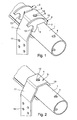
- first and a second Fastening element 2 or 3 On a pipe 1 are mounted one above the other over a not shown screw a first and a second Fastening element 2 or 3.
- the first fastening element 2 lies between the second fastening element 3 and the tube 1 directly on the tube 1.
- For attachment with the not shown screw has the tube through-holes 4, as shown in the drawing outside the fasteners 2, 3 are visible.
- the first fastening element 2 has a U-profile with a plane, plate-shaped closed area 5 and two U-legs, namely an open first leg 6 and a second closed U-leg 7.
- the legs 6 and 7 protrude from the plate-shaped closed area 5 in one obtuse angle from such that at a system of plate-shaped closed area 5 on the tube 1 the both U-legs 6, 7 tangent to the outer periphery of the Pipe 1 abut.
- the second fastening element 3 On the first fastener 2 is a second Fastener 3 on.
- the second fastening element 3 also has in its investment area opposite the tube. 1 a U-shaped profile with a closed bottom portion 9 and from this projecting U-legs, namely a first U-leg 10 and a second U-leg 11.
- the closed Floor area 9 is inside for a surface-locking Attachment to the plate-shaped closed region 5 of the first fastening element 2 is formed.
- the two U-thighs 10, 11 of the second fastening element 3 are in an equal obtuse angle to the closed one Floor area 9 angled as the respective U-legs of the first fastening element 2.
- Deviation Only in the second U-leg 11 of the second fastening element 3 is a Deviation from the aforementioned obtuse angle in one narrow transition region between the closed bottom 9 and the adjacent second U-leg 11. This Deviation is in the illustrated embodiment by the width of the first fastener 2 in Circumferential direction of the tube 1 conditionally and can at reduced Width of the relevant area 5 of the first Fastening element 2 also omitted.
- a passage opening 12 In the closed bottom area 9 of the second Fastening element 3 is a passage opening 12, in the circumferential direction of the tube 1 as a slot is trained.
- the passage openings 8 and 12 are such arranged that in juxtaposition of the two Fasteners 2, 3 a fastening screw through These two through holes 8, 12 in the tube. 1 can intervene.
- An embodiment of the passage opening 12 of the second fastener 3 is required because the second fastener 3 when resting on the first Fastener 2 with respect to the axis of the tube 1 to the Wall thickness of the second U-leg 7 of the first Fastener 2 is moved in parallel.
- FIG. 2 An attachment of the second fastening element 3 as a single part on the tube 1 is shown in Fig. 2, wherein the fastening screw is again not drawn.
- the first Fastener 2 designed such that at this in the semicircular openings 13 a tube can accommodate, the pipe by gluing, welding or soldering or in another similar way with the first Fastener 2 can be firmly connected.
- the second fastening element 3 is at its from the pipe protruding long free end with holes 14 for attachment for example, a holder for attaching a Wheel chocks provided.
Landscapes
- Engineering & Computer Science (AREA)
- Chemical & Material Sciences (AREA)
- Combustion & Propulsion (AREA)
- Transportation (AREA)
- Mechanical Engineering (AREA)
- Clamps And Clips (AREA)
- Mutual Connection Of Rods And Tubes (AREA)
Abstract
Description
- Fig. 1
- eine Befestigungseinrichtung an einem zylindrischen Rohr mit übereinander angeordnetem ersten und zweiten Befestigungselement,
- Fig. 2
- das Rohr nach Fig. 1 mit lediglich einem darauf aufgelegten zweiten Befestigungselement.
Claims (1)
- Befestigungseinrichtung an einem kreiszylindrischen Rohr (1) mit einem ersten und einem zweiten, lösbaren Befestigungselement (2) bzw. (3), von denen das erste Befestigungselement (2) zwischen dem zweiten Befestigungselement (3) und dem Rohr (1) liegen kann und beide Befestigungselemente folgende Merkmale aufweisen, nämlich bei dem ersten Befestigungselement (2)das erste Befestigungselement (2) besitzt einen U-förmig ausgebildeten Bereich zur Auflage auf dem Außenumfangsbereich des Rohres (1),der geschlossene, zwischen den U-Schenkeln (6, 7) liegende Bereich (5) ist in der Form im wesentlichen einer ebenen Platte ausgebildet,die U-Schenkel (6, 7) ragen von dem plattenförmigen, geschlossenen Bereich (5) über jeweils einen gleichen stumpfen Winkel ab, wobei die Größe des stumpfen Winkels für eine tangentiale Anlage der U-Schenkel (6, 7) an dem Außenumfang des Rohres (1) ausgelegt ist,die beiden U-Schenkel (6, 7) sind unterschiedlich ausgebildet, indem ein erster dieser U-Schenkel (6) in dem gesamten Bereich zwischen seinen in Achsrichtung des Rohres (1) ausgerichteten Enden offen ausgebildet ist, während der zweite U-Schenkel (7) in diesem Bereich zumindest teilweise geschlossen ist und in diesem geschlossenen Bereich im wesentlichen parallel zueinander verlaufende, ebene Innenund Außenwandflächen besitzt,in dem geschlossenen, plattenförmigen Bereich (5) des ersten Befestigungselementes (2) befindet sich eine Durchgangsöffnung (8) für die Aufnahme einer an dem Rohr (1) arretierbaren Schraube, und bei dem zweiten Befestigungselement (3)das zweite Befestigungselement (3) besitzt ebenfalls einen U-förmig ausgebildeten Bereich zur Auflage direkt oder indirekt über das erste Befestigungselement (2) auf einem Außenumfangsbereich des Rohres (1),der geschlossene, zwischen den U-Schenkeln (10, 11) des zweiten Befestigungselementes (3) liegende Bereich (9) verläuft innen zwischen den U-Schenkeln (10, 11) im wesentlichen eben,die U-Schenkel (10, 11) besitzen Bereiche, die gegenüber dem geschlossenen Bereich unter jeweils einem untereinander und mit Bezug auf die U-Schenkel (6, 7) des ersten Befestigungselementes (2) gleichen stumpfen Winkel verlaufen,in dem geschlossenen Bereich (9) mit der im wesentlichen eben verlaufenden Innenwand ist eine Durchgangsöffnung (12) für die Aufnahme einer an dem Rohr (1) arretierbaren Schraube vorgesehen,die Durchgangsöffnung (12) besitzt in Umfangsrichtung des Rohres (1) eine Länge, durch die einerseits bei Aufeinanderliegen von erstem und zweitem Befestigungselement (2, 3) der Durchgang einer Schraube zur Befestigung an dem Rohr (1) durch die Durchgangsöffnungen (8, 12) beider Befestigungselemente (2, 3) möglich ist und durch die andererseits auch eine Schrauben-Befestigung an dem Rohr (1) bei direkter Auflage des zweiten Befestigungselementes (3) als einzigem Befestigungselement auf dem Rohr (1) möglich ist.
Applications Claiming Priority (2)
| Application Number | Priority Date | Filing Date | Title |
|---|---|---|---|
| DE10203516 | 2002-01-30 | ||
| DE10203516A DE10203516C2 (de) | 2002-01-30 | 2002-01-30 | Befestigungseinrichtung an einem kreiszylindrischen Rohr |
Publications (3)
| Publication Number | Publication Date |
|---|---|
| EP1333209A2 true EP1333209A2 (de) | 2003-08-06 |
| EP1333209A3 EP1333209A3 (de) | 2003-10-22 |
| EP1333209B1 EP1333209B1 (de) | 2004-09-15 |
Family
ID=7713365
Family Applications (1)
| Application Number | Title | Priority Date | Filing Date |
|---|---|---|---|
| EP02027748A Expired - Lifetime EP1333209B1 (de) | 2002-01-30 | 2002-12-11 | Befestigungseinrichtung an einem kreiszylindrischen Rohr |
Country Status (2)
| Country | Link |
|---|---|
| EP (1) | EP1333209B1 (de) |
| DE (2) | DE10203516C2 (de) |
Cited By (1)
| Publication number | Priority date | Publication date | Assignee | Title |
|---|---|---|---|---|
| CN109398500A (zh) * | 2018-12-12 | 2019-03-01 | 中国重汽集团济南动力有限公司 | 一种重型汽车轮罩装置 |
Family Cites Families (7)
| Publication number | Priority date | Publication date | Assignee | Title |
|---|---|---|---|---|
| US2735693A (en) * | 1956-02-21 | Mud guard for tractor cab | ||
| US900545A (en) * | 1906-06-04 | 1908-10-06 | Steel Gain Mfg Company | Support for cross-arms. |
| US1714814A (en) * | 1925-09-22 | 1929-05-28 | Locke Insulator Corp | Pole bracket |
| US2919149A (en) * | 1958-04-28 | 1959-12-29 | Arthur C Farley | Structural connection |
| US4377294A (en) * | 1981-03-17 | 1983-03-22 | Lancaster Colony Corporation | Vehicle fender and support bar |
| JPH0826050A (ja) * | 1994-07-15 | 1996-01-30 | Shinsei Sangyo Kk | トラック用サイドガード |
| AU9538098A (en) * | 1998-08-31 | 2000-03-21 | Volvo Lastvagnar Ab | Device for underrun protection in vehicles |
-
2002
- 2002-01-30 DE DE10203516A patent/DE10203516C2/de not_active Expired - Fee Related
- 2002-12-11 EP EP02027748A patent/EP1333209B1/de not_active Expired - Lifetime
- 2002-12-11 DE DE50201003T patent/DE50201003D1/de not_active Expired - Fee Related
Cited By (1)
| Publication number | Priority date | Publication date | Assignee | Title |
|---|---|---|---|---|
| CN109398500A (zh) * | 2018-12-12 | 2019-03-01 | 中国重汽集团济南动力有限公司 | 一种重型汽车轮罩装置 |
Also Published As
| Publication number | Publication date |
|---|---|
| DE50201003D1 (de) | 2004-10-21 |
| EP1333209A3 (de) | 2003-10-22 |
| DE10203516A1 (de) | 2003-08-07 |
| EP1333209B1 (de) | 2004-09-15 |
| DE10203516C2 (de) | 2003-12-24 |
Similar Documents
| Publication | Publication Date | Title |
|---|---|---|
| DE69902550T2 (de) | Langgestreckte tragstruktur mit hohlprofilträger mit einem querflansch an beiden endflächen | |
| EP0561848B1 (de) | Türsäule an einer karosserie eines personenkraftwagens | |
| DE69809031T2 (de) | Fahrzeugbeladungsvorrichtung | |
| DE19814975B4 (de) | Trägersystem für Nutzfahrzeuge | |
| DE1951271C3 (de) | Einzelradaufhängung für Kraftfahrzeuge | |
| DE69604897T2 (de) | Trägerplatte eines scheibenwischer-mechanismus | |
| WO2005075281A1 (de) | Verbindungsbereich zur anbindung eines anbauteils an eine fahrzeugkarosserie | |
| DE60226087T2 (de) | Fahrzeugkarrosseriestruktur, Fahrzeug mit einer solchen Struktur, Verfahren zum Befestigen einer Lenksäule an der Fahrzeugkarosserie und mit einem solchen Befestigungsverfahren hergestelltes Fahrzeug | |
| AT390035B (de) | Fluessigkeitsbehaelter, insbesondere kraftstoffbehaelter, fuer kraftfahrzeuge | |
| DE3612311A1 (de) | An einem motorradrahmen befestigbares, einteiliges halterungsteil | |
| EP1333209B1 (de) | Befestigungseinrichtung an einem kreiszylindrischen Rohr | |
| DE10351446B4 (de) | Gewindeplatte | |
| DE4114960A1 (de) | Aufnahmepunkte an einer fahrzeugkarosserie zur aufnahme von loesbaren anschlussteilen | |
| DE19648450A1 (de) | Anhänger für Personenkraftwagen | |
| EP0972688A2 (de) | Hubeinrichtung mit Schaftrohr und Stützrohr | |
| EP1771310B1 (de) | Zylinderbaugruppe mit einem achsanschluss | |
| DE3878447T2 (de) | Rahmenprofil, das als strukturelement zur versteifung von anzeigetafeln, insbesondere von verkehrszeichen, geeignet ist, und das als sicherungselement fuer die schraubenbolzen, die fuer die befestigung der anzeigetafeln an entsprechenden stuetzpfaehlen vorgesehen sind, dient. | |
| DE202023104160U1 (de) | Stützbeschlag für eine Fahrzeugachse | |
| DE102012221983B4 (de) | Konsole zur Verbindung von Dachaufbauten eines Schienenfahrzeugs mit dem Schienenfahrzeug | |
| DE3045325A1 (de) | Haltevorrichtung fuer kotfluegel an lastkraftwagen, anhaengern oder sonstigen fahrzeugen | |
| EP0470526B1 (de) | Vorrichtung zum Befestigen einer Gummifederachse am Rahmen eines Fahrzeuges | |
| EP0951113A2 (de) | Rechteckiges Gehäuse zur Aufnahme elektrischer oder eletronischer Bauteile | |
| DE705251C (de) | Rohrachse fuer Ackerwagen | |
| DE102016013751C5 (de) | Nutzfahrzeugaufbau | |
| DE7615703U1 (de) | Fahrgestell für Anhänger |
Legal Events
| Date | Code | Title | Description |
|---|---|---|---|
| PUAI | Public reference made under article 153(3) epc to a published international application that has entered the european phase |
Free format text: ORIGINAL CODE: 0009012 |
|
| AK | Designated contracting states |
Designated state(s): AT BE BG CH CY CZ DE DK EE ES FI FR GB GR IE IT LI LU MC NL PT SE SI SK TR |
|
| AX | Request for extension of the european patent |
Extension state: AL LT LV MK RO |
|
| PUAL | Search report despatched |
Free format text: ORIGINAL CODE: 0009013 |
|
| RIC1 | Information provided on ipc code assigned before grant |
Ipc: 7F 16L 3/10 A Ipc: 7B 62D 25/16 B |
|
| AK | Designated contracting states |
Kind code of ref document: A3 Designated state(s): AT BE BG CH CY CZ DE DK EE ES FI FR GB GR IE IT LI LU MC NL PT SE SI SK TR |
|
| AX | Request for extension of the european patent |
Extension state: AL LT LV MK RO |
|
| 17P | Request for examination filed |
Effective date: 20030925 |
|
| GRAP | Despatch of communication of intention to grant a patent |
Free format text: ORIGINAL CODE: EPIDOSNIGR1 |
|
| GRAS | Grant fee paid |
Free format text: ORIGINAL CODE: EPIDOSNIGR3 |
|
| AKX | Designation fees paid |
Designated state(s): DE FR IT SE |
|
| GRAA | (expected) grant |
Free format text: ORIGINAL CODE: 0009210 |
|
| AK | Designated contracting states |
Kind code of ref document: B1 Designated state(s): DE FR IT SE |
|
| REG | Reference to a national code |
Ref country code: IE Ref legal event code: FG4D Free format text: GERMAN |
|
| REF | Corresponds to: |
Ref document number: 50201003 Country of ref document: DE Date of ref document: 20041021 Kind code of ref document: P |
|
| REG | Reference to a national code |
Ref country code: SE Ref legal event code: TRGR |
|
| REG | Reference to a national code |
Ref country code: IE Ref legal event code: FD4D |
|
| ET | Fr: translation filed | ||
| PLBE | No opposition filed within time limit |
Free format text: ORIGINAL CODE: 0009261 |
|
| STAA | Information on the status of an ep patent application or granted ep patent |
Free format text: STATUS: NO OPPOSITION FILED WITHIN TIME LIMIT |
|
| 26N | No opposition filed |
Effective date: 20050616 |
|
| PGFP | Annual fee paid to national office [announced via postgrant information from national office to epo] |
Ref country code: IT Payment date: 20081222 Year of fee payment: 7 Ref country code: SE Payment date: 20081212 Year of fee payment: 7 |
|
| PGFP | Annual fee paid to national office [announced via postgrant information from national office to epo] |
Ref country code: FR Payment date: 20081212 Year of fee payment: 7 |
|
| PGFP | Annual fee paid to national office [announced via postgrant information from national office to epo] |
Ref country code: DE Payment date: 20081219 Year of fee payment: 7 |
|
| REG | Reference to a national code |
Ref country code: FR Ref legal event code: CA Ref country code: FR Ref legal event code: CD |
|
| EUG | Se: european patent has lapsed | ||
| REG | Reference to a national code |
Ref country code: FR Ref legal event code: ST Effective date: 20100831 |
|
| PG25 | Lapsed in a contracting state [announced via postgrant information from national office to epo] |
Ref country code: FR Free format text: LAPSE BECAUSE OF NON-PAYMENT OF DUE FEES Effective date: 20091231 |
|
| PG25 | Lapsed in a contracting state [announced via postgrant information from national office to epo] |
Ref country code: DE Free format text: LAPSE BECAUSE OF NON-PAYMENT OF DUE FEES Effective date: 20100701 |
|
| PG25 | Lapsed in a contracting state [announced via postgrant information from national office to epo] |
Ref country code: IT Free format text: LAPSE BECAUSE OF NON-PAYMENT OF DUE FEES Effective date: 20091211 |
|
| PG25 | Lapsed in a contracting state [announced via postgrant information from national office to epo] |
Ref country code: SE Free format text: LAPSE BECAUSE OF NON-PAYMENT OF DUE FEES Effective date: 20091212 |