EP1333139A1 - Fenster-/Türzusatzschloss - Google Patents
Fenster-/Türzusatzschloss Download PDFInfo
- Publication number
- EP1333139A1 EP1333139A1 EP02024046A EP02024046A EP1333139A1 EP 1333139 A1 EP1333139 A1 EP 1333139A1 EP 02024046 A EP02024046 A EP 02024046A EP 02024046 A EP02024046 A EP 02024046A EP 1333139 A1 EP1333139 A1 EP 1333139A1
- Authority
- EP
- European Patent Office
- Prior art keywords
- locking
- bolt
- base part
- locking bolt
- additional lock
- Prior art date
- Legal status (The legal status is an assumption and is not a legal conclusion. Google has not performed a legal analysis and makes no representation as to the accuracy of the status listed.)
- Granted
Links
- 230000000903 blocking effect Effects 0.000 claims description 25
- 229910000831 Steel Inorganic materials 0.000 claims description 7
- 238000013016 damping Methods 0.000 claims description 7
- 239000010959 steel Substances 0.000 claims description 7
- 230000007246 mechanism Effects 0.000 description 9
- 230000008901 benefit Effects 0.000 description 3
- 229910001229 Pot metal Inorganic materials 0.000 description 2
- 230000001133 acceleration Effects 0.000 description 2
- 238000005452 bending Methods 0.000 description 2
- 230000000295 complement effect Effects 0.000 description 2
- 230000003993 interaction Effects 0.000 description 2
- 241001295925 Gegenes Species 0.000 description 1
- 230000009471 action Effects 0.000 description 1
- 230000008878 coupling Effects 0.000 description 1
- 238000010168 coupling process Methods 0.000 description 1
- 238000005859 coupling reaction Methods 0.000 description 1
- 238000002635 electroconvulsive therapy Methods 0.000 description 1
- 210000003746 feather Anatomy 0.000 description 1
- 239000006260 foam Substances 0.000 description 1
- 230000001771 impaired effect Effects 0.000 description 1
- 238000004519 manufacturing process Methods 0.000 description 1
- 238000000034 method Methods 0.000 description 1
- 230000002028 premature Effects 0.000 description 1
- 238000003825 pressing Methods 0.000 description 1
- 230000008569 process Effects 0.000 description 1
- 238000004080 punching Methods 0.000 description 1
- 230000000284 resting effect Effects 0.000 description 1
- 230000007480 spreading Effects 0.000 description 1
- 238000003892 spreading Methods 0.000 description 1
Images

Classifications
-
- E—FIXED CONSTRUCTIONS
- E05—LOCKS; KEYS; WINDOW OR DOOR FITTINGS; SAFES
- E05C—BOLTS OR FASTENING DEVICES FOR WINGS, SPECIALLY FOR DOORS OR WINDOWS
- E05C1/00—Fastening devices with bolts moving rectilinearly
- E05C1/02—Fastening devices with bolts moving rectilinearly without latching action
- E05C1/04—Fastening devices with bolts moving rectilinearly without latching action with operating handle or equivalent member rigid with the bolt
-
- E—FIXED CONSTRUCTIONS
- E05—LOCKS; KEYS; WINDOW OR DOOR FITTINGS; SAFES
- E05B—LOCKS; ACCESSORIES THEREFOR; HANDCUFFS
- E05B15/00—Other details of locks; Parts for engagement by bolts of fastening devices
- E05B15/10—Bolts of locks or night latches
- E05B15/101—Spring-retracted bolts
-
- E—FIXED CONSTRUCTIONS
- E05—LOCKS; KEYS; WINDOW OR DOOR FITTINGS; SAFES
- E05B—LOCKS; ACCESSORIES THEREFOR; HANDCUFFS
- E05B63/00—Locks or fastenings with special structural characteristics
- E05B63/0004—Additional locks added to existing lock arrangements
Definitions
- the invention relates to an additional lock for a window or a door, the at least one base part attachable to the window or door, one Locking latch that is used to lock the window or door from one Release position along a locking direction in a locking position is movable, and a attachable to the base part Has lid part.
- Such an additional lock is used for additional Securing the window or door against forced opening.
- the locking bolt engages in an associated one in the locking position Striker on the window or door or in a lock box, depending on whether the additional lock for outside or after interior opening windows or doors is provided.
- the base part is known for windows and doors opening outwards Made of die-cast zinc, with the base part against one a rear housing area in the locking direction Inclusion of a locking cylinder and a locking mechanism for connection of the locking cylinder with the locking bolt.
- On one in Locking direction located front area as well as inside fastening openings are provided in a central region of the base part, by means of which the base part is screwed to the window or door can be.
- the base part has this front area also a recess for guiding the locking bolt during the locking movement.
- the basic part with the bolt mechanism contained therein is closed on its underside by a screwed cover plate. With such an additional lock, the base part becomes attach it to the window or door with the cover part.
- This object is achieved in that the base part on one in the locking direction located front area and on an opposite at least the rear side area located in the locking direction a fastening device for fastening the base part to the Has window or the door, and that the base part on the front area and at least one bar holding means on the rear side area to secure the one in the locked position Has locking bolt on the base part.
- the additional lock according to the invention there are therefore two - in relation to the locking direction - opposite areas fastening devices provided by means of which the base part on the window or the door attached, for example screwed.
- This Areas are used in the context of the invention as a front area and back area designated.
- a bar holding means for example a bending tongue with a receiving opening is provided, through which the locking bolt is guided and in the event of an attempted break-in is held on the base part.
- the additional lock according to the invention is suitable for reliable Securing both from the outside and from the inside opening windows and doors.
- the additional lock exerted very different loads. Because of the arrangement of fasteners and latch holders both on the front area as well as the rear area of the base these forces can be optimally absorbed in both applications and be distributed.
- the additional lock according to the invention thus offers the advantage that it is for the two stress cases explained are compatible, so that it is in one is suitable for a wide range of applications.
- the arrangement of the fastening devices and The latch holding means should also be noted that the front area mentioned and back area from a central or central Area of the base part to be distinguished.
- the Front area and the back area through the front or rear third of the base preferably even only by the front and rear quarters of the base part formed.
- the invention is also for additional locks with several, in particular parallel locking bolts suitable without further ado.
- a lock cylinder that provided to secure the locking bolt in the locking position is, or a lock cylinder housing connected to this lock cylinder be preassembled on the cover part.
- a lock cylinder housing connected to this lock cylinder be preassembled on the cover part.
- cooperating fasteners for example Latching means provided.
- the locking cylinder is preassembled on the cover part can and therefore not intended for pre-assembly on the base part or is integrated into this, exist on the part of the basic part with regard the arrangement of the fastening devices and transom holding means none undesirable restrictions due to the presence of the locking cylinder.
- the fasteners and latch holding means can thus optimized for the respective load case on the front area and the rear portion of the base to be arranged around the to achieve the explained advantage of the universal application. Also the attachment of the base part to the window or door, in particular screwing the base part is easier because - on the part of the cover part pre-assembled - locking cylinder the accessibility of the fastening devices not affected.
- This embodiment thus enables the following advantageously simple Assembly and fastening of the additional lock: First, the factory the locking cylinder is pre-assembled on the cover part. Furthermore, the Locking bolts are preassembled on the base part. The user attached the base of the pre-assembled lock in the desired Position on the window or door. Finally the user fastens for the purpose of final assembly, the pre-assembled cover part on the already pre-assembled and attached to the window or door. Furthermore, the user can use a counterpart on the window or the door.
- a locking cylinder to secure the locking bolt in the locking position as well a rotatable preloaded rotary latch is provided, the Rotary lock for locking or releasing the locking bolt for one with the locking bolt and the other with the locking cylinder interacts.
- a coupling of the lock cylinder and Locking latch via a rotary bolt has the advantage of being advantageous convenient automatic function for locking the locking bolt can be realized without the risk of unauthorized unlocking of the locking bolt by external impacts on the locking mechanism consists.
- a preloaded locking bolt can be used by simple manual pushing movement - without turning of the cylinder lock - from the release position to the locking position to be brought.
- the snaps between the locking bolt and the locking mechanism provided locking mechanism briefly back to to allow the locking bolt to pass first and then block the locking bolt in the locked position. If this locking mechanism is linear, i.e. is straight, can accelerated by intermittent blows from outside become an unwanted release of the previously blocked Locking bolt can lead.
- the locking mechanism between the locking cylinder and locking bolt is designed as a rotary bolt and by such blows on the additional lock no rotational acceleration of the bolt mechanism can be generated can, in this embodiment - despite the automatic function - one unauthorized unlocking effectively by such a shock treatment prevented.
- the base part as a side view U-shaped bracket with a base plate and two perforated legs which form the bolt holding means for the locking bolt.
- Such one U-bracket has a simple structure and can - for example through a punching / bending process can be produced particularly easily.
- the latch holding means are formed by receiving openings, which together define a through channel for the locking bolt. The fasteners can be easily punched fastening openings are formed.
- such a U-bracket can be easily made of steel, in particular are made of tempered steel, which - in particular compared to a base made of die-cast zinc - a particularly high one Stability and security is achieved.
- the locking bolt with a locking pin is provided, for example, inserted in a security channel or can be pressed in, which is transverse to the longitudinal direction of the locking bolt runs.
- a locking pin can be used, for example serve to permanently connect an actuating element to the locking bolt, through which the locking bolt - especially for the explained Automatic function - can be operated manually.
- a locking pin can serve as a stop element, that the locking bolt in the release position against further movement secures against the locking direction.
- a Damping device is provided through which the release movement the locking bolt is damped against the locking direction. This prevents premature wear of the additional lock.
- the damping device can be, for example, an envelope, in particular made of plastic, on the locking pin of the locking bolt exhibit.
- the base part, the Cover part or the locking bolt a damping element, for example attached from foam, for example glued, the one The impact of the locking bolt or the locking pin dampens.
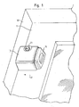
- Fig. 1 shows an additional lock through which a closable on the inside, outwardly opening window sash 11 additionally against violent opening can be secured.
- a closable on the inside, outwardly opening window sash 11 additionally against violent opening can be secured.
- it is Additional lock attached to the inside of the window sash 11 shown.
- a cover part 13 serving as a cover and a Actuating element arranged on the back of the additional lock 15, which is connected to a locking bolt (not shown).
- a locking bolt not shown
- FIG. 2a and 2b illustrate the suitability of the additional lock according to the invention for reliable securing both from the outside and from inward opening windows or doors.
- a base part 25 of the additional lock is shown. This is designed as a U-bracket, with a base plate 27 and two perforated legs 29, 31. On the base plate 27 there are fastening openings 33, 35 formed through which the base part 25 by means of fastening screws 37 is attached to the window sash 11.
- a cylindrical locking bolt 43 is located within the perforated legs 29, 31 guided. This is in the locked position in which it is in a Receiving opening 45 of the window reveal 19 (FIG. 2a) or into a receiving opening 47 of an L-shaped counterpart 49 engages by means of a fastening screw 51 is fastened to the window reveal 19 (FIG. 2 B).
- the exposure situation is when trying to break in that shown in Fig. 2b, after in opening window:
- the basic part exercises 25 on the front side area 39 on the window sash 11 Compressive force against the opening direction 23.
- the rear side area 41 comes there on the rear side area 41 to a tensile load between the base part 25 and window sash 11, because the locking bolt 43 for a pivoting movement is forced clockwise.
- they are on that Back area 41 provided mounting holes 33 and mounting screws 37 arranged at the optimal point of attack to a unwanted detachment of the base part 25 from the window sash 11 prevent due to the tensile load.
- the rear perforated leg 31 arranged particularly effective.
- the additional lock according to the invention thus provides for the two in FIG. 2a and 2b shown load situations a particularly reliable Protection against a breakaway of the locking bolt 43 from the base and against violent detachment of the base part 25 from the window sash 11.
- the additional lock is therefore the same for both applications suitable.
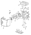
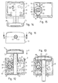
- Fig. 3 shows the parts of the additional lock in an exploded view.
- the base part 25 has an essentially rectangular basic shape, with a front fastening opening 33 in the area of each corner or a rear fastening opening 35 is provided. Moreover additional fastening openings 53 are provided. Furthermore, the Base part 25 on the base plate 27 has an anti-rotation recess 55 on.
- the two perforated legs 29, 31 of the base part 25 each have one Receiving opening 57 for receiving the locking bolt 43.
- the rear Perforated leg 31 has a profile contour.
- the locking bolt 43 has a cylindrical basic shape and is made of tempered steel, so that it has a particularly high stability.
- the actuating element 15 has a substantially cuboid Attack part 59 and a connecting shaft 61 formed thereon. At the end of the connecting shaft 61 there is a lateral blocking lug 63 formed.
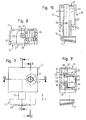
- the actuating element 15 and the locking bolt 43 can be preassembled by the locking bolt 43 partially in the connecting shaft 61 inserted and there by means of a locking pin 65 is secured, the transverse to the locking direction 17 by Security openings 67 of the connecting shaft 61 in a security channel 69 of the locking bolt 43 is pressed in (see FIGS. 5, 12, 13).
- a counterpart to the front end of the locking bolt 43 may be provided, for example, a striking plate 71, the one central receiving opening 73 and two lateral fastening openings 75 having.
- the hood-shaped cover part 13 is open at the bottom and has at the top an access opening 77 for the lock cylinder 21.
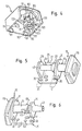
- An the front facing in the locking direction 17 are a bolt opening 79 and two mounting recesses 81 are provided (see FIG. 4).
- the back of the cover part 13 is complementary to the profile contour of the Perforated leg 31 of the base part 25 is formed.
- the cover part 13 on the inside of its top a substantially circular section Housing bracket 83 on which to accommodate a Lock cylinder 21 and a rotary bolt 85 encompassing the lock cylinder housing 87 is provided and surrounds the access opening 77 (see FIG. 8, 9, 12, 13).
- the housing holder 83 is formed with a downwardly projecting locking lug 88 (see Fig. 4, 9).
- the locking cylinder 21 has a lateral rotation blocking lug 89 the bottom of the lock cylinder 21 has a rotary actuation approach 91 (see Fig. 4, 15).
- the rotary latch 85 has the basic shape of an open on the end faces Cylinder jacket with a lateral locking channel recess 93 and a freewheel recess extending therefrom to the top of the rotary latch 85 95.
- On the underside of the rotary latch 85 is a driver attachment 101, with the rotary actuating lug 91 of the locking cylinder 21 cooperates, and a blocking projection 102 is formed (cf. FIG. 4, 15).
- the lock cylinder housing 87 essentially has an annular shape a side rotation lock receptacle 103 for receiving the rotation lock approach 89 of the lock cylinder 21.
- On the underside of the lock cylinder housing 87 are a securing collar 105 for mounting the rotary bolt 85 and a rotation lock cam 107 for engaging in the rotation lock recess 55 of the base part 25 is formed.
- On the security collar 105 is a radially inward blocking stop 109 formed, which cooperates with the locking projection 102 of the rotary latch 85 (see Fig. 4, 15).
- the bottom of the lock cylinder housing 87 is formed as a ring edge 111, on which the locking lug 88 of the housing bracket 83 attacks (see Fig. 9, 15).
- the locking bolt 43 is preassembled on the base part 25 by against the locking direction 17 one shown in Fig. 10, 12, 13 Spring 113 and in the locking direction 17 of the connecting shaft 61 of the Actuator 15 are placed on the locking bolt 43 and this arrangement between the two perforated legs 29, 31 of the base part 25 by inserting the locking pin 65 into the locking opening 67 and the securing channel 69 is fixed (cf. FIG. 5).
- the pre-assembled base part 25 can now by the user on the Window sash 11 are attached by attaching them to the front mounting openings 33 and the rear fastening openings 35 with the window sash 11 is screwed. This attachment of the base part 25 is not affected by the presence of the lock cylinder 21 or Lock cylinder housing 87 impaired, since this on the cover part 13th are arranged.
- a lock can in other words, automatically, without actuating the locking cylinder 21, and the locking of the locking bolt 43 in the locking position takes place by means of a rotary bolt 85, which despite this automatic function particularly high security against unauthorized unlocking by offers intermittent stroke acceleration.
Landscapes
- Engineering & Computer Science (AREA)
- Mechanical Engineering (AREA)
- Lock And Its Accessories (AREA)
Abstract
Description
- Fig. 1
- eine Perspektivansicht eines an einem Fensterflügel endmontierten, verriegelten Zusatzschlosses,
- Fig. 2a und 2b
- eine Seitenansicht der Anordnung eines Zusatzschlosses an einem nach außen bzw. nach innen öffnenden Fenster,
- Fig. 3
- eine Explosionsdarstellung eines erfindungsgemäßen Zusatzschlosses,
- Fig. 4
- eine Perspektivansicht eines vormontierten Deckelteils,
- Fig. 5 und 6
- Perspektivansichten eines vormontierten Grundteils in der Freigabestellung bzw. Verriegelungsstellung,
- Fig. 7
- eine Draufsicht auf das Zusatzschloss in der Freigabestellung,
- Fig. 8, 9 und 10
- Querschnittsansichten entlang der Ebenen XIII-XIII, IX-IX bzw. X-X gemäß Fig. 7,
- Fig. 11
- eine Vorderansicht des Zusatzschlosses,
- Fig. 12
- eine Querschnittsansicht entlang der Ebene XII-XII gemäß Fig. 11 in der Freigabestellung,
- Fig. 13
- eine der Fig. 12 entsprechende Querschnittsansicht, jedoch in Verriegelungsstellung,
- Fig. 14
- eine Unteransicht des Zusatzschlosses, und
- Fig. 15
- eine der Fig. 14 entsprechende Unteransicht des vormontierten Deckelteils.
- 11
- Fensterflügel
- 13
- Deckelteil
- 15
- Betätigungselement
- 17
- Verriegelungsrichtung
- 19
- Fensterlaibung
- 21
- Schließzylinder
- 23
- Öffnungsrichtung des Fensters bzw. der Tür
- 25
- Grundteil
- 27
- Grundplatte
- 29
- Lochschenkel
- 31
- Lochschenkel
- 33
- Befestigungsöffnung
- 35
- Befestigungsöffnung
- 37
- Befestigungsschraube
- 39
- Vorderseitenbereich
- 41
- Rückseitenbereich
- 43
- Schließriegel
- 45
- Aufnahmeöffnung
- 47
- Aufnahmeöffnung
- 49
- Gegenstück
- 51
- Befestigungsschraube
- 53
- Befestigungsöffnung
- 55
- Drehsicherungsausnehmung
- 57
- Aufnahmeöffnung
- 59
- Angriffsteil
- 61
- Verbindungsschaft
- 63
- Blockiernase
- 65
- Sicherungsstift
- 67
- Sicherungsöffnung
- 69
- Sicherungskanal
- 71
- Schließblech
- 73
- Aufnahmeöffnung
- 75
- Befestigungsöffnung
- 77
- Schließzylinder-Zugangsöffnung
- 79
- Riegelöffnung
- 81
- Montageaussparung
- 83
- Gehäusehalterung
- 85
- Drehriegel
- 87
- Schließzylindergehäuse
- 88
- Rastnase
- 89
- Drehblockieransatz
- 91
- Drehbetätigungsansatz
- 93
- Riegelkanalaussparung
- 95
- Freilaufaussparung
- 97
- Mitnehmer- / Blockieransatz
- 99
- Fixiernocken
- 101
- Mitnehmeransatz
- 102
- Blockieransatz
- 103
- Drehblockieraufnahme
- 105
- Sicherungsbund
- 107
- Drehsicherungsnocken
- 109
- Blockieranschlag
- 111
- Ringkante
- 113
- Feder
Claims (10)
- Zusatzschloss für ein Fenster (11, 19) oder eine Tür, wenigstens mitwobei das Grundteil (25) an einem in Verriegelungsrichtung (17) gelegenen Vorderseitenbereich (39) und an einem entgegen der Verriegelungsrichtung (17) gelegenen Rückseitenbereich (41) jeweils wenigstens eine Befestigungseinrichtung (33, 35) zur Befestigung des Grundteils an dem Fenster oder der Tür aufweist, undeinem an dem Fenster oder der Tür befestigbaren Grundteil (25),einem Schließriegel (43), der zur Verriegelung des Fensters oder der Tür von einer Freigabestellung entlang einer Verriegelungsrichtung (17) in eine Verriegelungsstellung bewegbar ist, undeinem an dem Grundteil befestigbaren Deckelteil (13),
wobei das Grundteil (25) an dem Vorderseitenbereich (39) und an dem Rückseitenbereich (41) jeweils wenigstens ein Riegelhaltemittel (29, 31) zur Sicherung des in der Verriegelungsstellung befindlichen Schließriegels (43) an dem Grundteil aufweist. - Zusatzschloss nach Anspruch 1,
dadurch gekennzeichnet, dass ein Schließzylinder (21) zur Sicherung des Schließriegels (43) in der Verriegelungsstellung vorgesehen ist,
wobei das Deckelteil (13) einerseits und der Schließzylinder (21) oder ein Schließzylindergehäuse (87) andererseits zusammenwirkende Befestigungsmittel (88, 111) zur Vormontage des Schließzylinders (21) an dem Deckelteil (13) aufweisen, wobei die Befestigungsmittel vorzugsweise durch Rastmittel (88) gebildet sind. - Zusatzschloss nach einem der vorhergehenden Ansprüche,
dadurch gekennzeichnet, dass das Grundteil (25) und das Deckelteil (13) zusammenwirkende Verbindungsmittel (31, 79, 43) zur Endmontage des vormontierten Deckelteils an dem Grundteil aufweisen,
wobei die Verbindungsmittel vorzugsweise eine Formschlussverbindung bilden. - Zusatzschloss nach einem der vorhergehenden Ansprüche,
dadurch gekennzeichnet, dass ein Schließzylinder (21) zur Sicherung des Schließriegels (43) in der Verriegelungsstellung vorgesehen ist,
wobei ferner ein drehbeweglicher vorgespannter Drehriegel (85) vorgesehen ist, der zur Verriegelung oder Freigabe des Schließriegels (43) mit einem Blockiermittel (63) des Schließriegels zusammenwirkt und über eine Mitnehmereinrichtung (101) mit dem Schließzylinder (21) drehbetätigbar verbunden ist. - Zusatzschloss nach Anspruch 4,
dadurch gekennzeichnet, dass das Blockiermittel des Schließriegels eine Blockiernase (63) aufweist, die mit einem Mitnehmer-/Blockieransatz (97) des Drehriegels zusammenwirkt, und/oder
dass zur Drehbetätigung des Drehriegels (85) der Schließzylinder (21) ein Drehbetätigungselement (91) aufweist, das mit der Mitnehmereinrichtung (101) des Drehriegels zusammenwirkt, und/oder dass der Drehriegel (85) gemeinsam mit dem Schließzylinder (21) an dem Deckelteil (13) vormontierbar ist. - Zusatzschloss nach einem der Ansprüche 4 und 5,
dadurch gekennzeichnet, dass eine Drehsicherungseinrichtung vorgesehen ist, durch die bei an dem Grundteil (25) endmontierten Deckelteil (13) der Drehriegel (85) gegen eine unbefugte Drehbewegung relativ zu dem Grundteil gesichert ist,
wobei die Drehsicherungseinrichtung insbesondere eine Drehsicherungsausnehmung (55) und einen hiermit in Eingriff stehenden Drehsicherungsnocken (107) aufweist, die an dem Drehriegel, dem Schließzylinder oder einem Schließzylindergehäuse (87) einerseits und an dem Grundteil (25) andererseits ausgebildet sind. - Zusatzschloss nach einem der vorhergehenden Ansprüche,
dadurch gekennzeichnet, dass das Grundteil (25) eine im Wesentlichen rechteckige Grundform aufweist, wobei im Bereich jeder Ecke eine Befestigungseinrichtung (33, 35) vorgesehen ist, und/oder
dass die Befestigungseinrichtungen des Grundteils (25) durch Befestigungsöffnungen (33, 35) gebildet sind, und/oder
dass das Grundteil (25) als U-Bügel mit einer Grundplatte (27) und zwei die Riegelhaltemittel bildenden Lochschenkeln (29, 31) ausgebildet ist, und/oder
dass das Grundteil (25) aus Stahl, insbesondere aus vergütetem Stahl gefertigt ist. - Zusatzschloss nach einem der vorhergehenden Ansprüche,
dadurch gekennzeichnet, dass der Schließriegel (43) an dem Grundteil (25) durch ein Federelement (113) vorgespannt und mittels eines Sicherungsstifts (65) gesichert ist. - Zusatzschloss nach Anspruch 8,
dadurch gekennzeichnet, dass der Schließriegel (43) ein Betätigungselement (15) zur Bewegung des Schließriegels in die Verriegelungsstellung aufweist, wobei das Betätigungselement (15) mittels des Sicherungsstifts (65) an dem Schließriegel gesichert ist, und/oder
dass der Schließriegel (43), der Sicherungsstift (65) und ein Riegelhaltemittel (29, 31) des Grundteils (25) dergestalt angeordnet sind, dass der Sicherungsstift (65) als Anschlagelement zur Sicherung des Schließriegels in der Freigabestellung dient. - Zusatzschloss nach einem der vorhergehenden Ansprüche,
dadurch gekennzeichnet, dass der Schließriegel (43) zur Vormontage an dem Grundteil (25) ausgebildet ist, und/oder
dass der Schließriegel (43) aus Stahl, insbesondere aus vergütetem Stahl gefertigt ist, und/oder
dass eine Dämpfungseinrichtung zur Dämpfung einer Freigabebewegung des Schließriegels von der Verriegelungsstellung in die Freigabestellung vorgesehen ist, wobei die Dämpfungseinrichtung vorzugsweise eine Umhüllung an einem Sicherungs- oder Anschlagstift oder ein an dem Grundteil, dem Deckelteil oder dem Schließriegel vorgesehenes Dämpfungselement aufweist, und/oder
dass ferner ein an dem Fenster oder der Tür befestigbares Gegenstück (71) vorgesehen ist zur Aufnahme des Schließriegels (43) in der Verriegelungsstellung.
Applications Claiming Priority (2)
| Application Number | Priority Date | Filing Date | Title |
|---|---|---|---|
| DE2002103858 DE10203858A1 (de) | 2002-01-31 | 2002-01-31 | Fenster-/Türzusatzschloss |
| DE10203858 | 2002-01-31 |
Publications (2)
| Publication Number | Publication Date |
|---|---|
| EP1333139A1 true EP1333139A1 (de) | 2003-08-06 |
| EP1333139B1 EP1333139B1 (de) | 2008-04-09 |
Family
ID=7713479
Family Applications (1)
| Application Number | Title | Priority Date | Filing Date |
|---|---|---|---|
| EP02024046A Expired - Lifetime EP1333139B1 (de) | 2002-01-31 | 2002-10-28 | Fenster-/Türzusatzschloss |
Country Status (2)
| Country | Link |
|---|---|
| EP (1) | EP1333139B1 (de) |
| DE (2) | DE10203858A1 (de) |
Cited By (2)
| Publication number | Priority date | Publication date | Assignee | Title |
|---|---|---|---|---|
| EP2796645A3 (de) * | 2013-04-23 | 2016-06-08 | Martin Lehmann GmbH & Co. Kg | Riegelschloss eines Möbels |
| IT201600088863A1 (it) * | 2016-09-01 | 2018-03-01 | Romano Clari | Dispositivo di blocco rapido di sicurezza per persiane,porte,ante apribili o scorrevoli di immobili e/o veicoli merci |
Families Citing this family (3)
| Publication number | Priority date | Publication date | Assignee | Title |
|---|---|---|---|---|
| DE102009059066A1 (de) | 2009-12-18 | 2011-06-22 | DORMA GmbH + Co. KG, 58256 | Sicherheitsvorrichtung für ein Flügelelement |
| DE202010007511U1 (de) | 2010-06-02 | 2010-10-07 | Finzel, Evelyn | Bügelsicherung für die Innenverriegelung von Haus- bzw. Balkontüren |
| WO2020047614A1 (en) * | 2018-09-07 | 2020-03-12 | Automatic Technology (Australia) Pty Ltd | A lock unit |
Citations (7)
| Publication number | Priority date | Publication date | Assignee | Title |
|---|---|---|---|---|
| DE204683C (de) * | ||||
| US1564953A (en) * | 1925-07-07 | 1925-12-08 | Abraham E Gertsfeld | Lock |
| US2468406A (en) * | 1946-05-03 | 1949-04-26 | Mora Jose | Lock |
| US2631877A (en) * | 1950-07-28 | 1953-03-17 | Ainsworth Mark | Lockable slide bolt assembly for doors and the like |
| US4179143A (en) * | 1978-01-31 | 1979-12-18 | Shy Min C | Fixed latch lock |
| US5275029A (en) * | 1992-07-13 | 1994-01-04 | Fort Lock Corporation | Refrigerator door lock |
| NL1012724C2 (nl) * | 1999-07-28 | 2001-02-01 | Stenman Holland Nv | Oplegslot. |
Family Cites Families (1)
| Publication number | Priority date | Publication date | Assignee | Title |
|---|---|---|---|---|
| US5618066A (en) * | 1995-11-13 | 1997-04-08 | Fu-Hsiang; Chen | Automatic latch device |
-
2002
- 2002-01-31 DE DE2002103858 patent/DE10203858A1/de not_active Withdrawn
- 2002-10-28 DE DE50212061T patent/DE50212061D1/de not_active Expired - Lifetime
- 2002-10-28 EP EP02024046A patent/EP1333139B1/de not_active Expired - Lifetime
Patent Citations (7)
| Publication number | Priority date | Publication date | Assignee | Title |
|---|---|---|---|---|
| DE204683C (de) * | ||||
| US1564953A (en) * | 1925-07-07 | 1925-12-08 | Abraham E Gertsfeld | Lock |
| US2468406A (en) * | 1946-05-03 | 1949-04-26 | Mora Jose | Lock |
| US2631877A (en) * | 1950-07-28 | 1953-03-17 | Ainsworth Mark | Lockable slide bolt assembly for doors and the like |
| US4179143A (en) * | 1978-01-31 | 1979-12-18 | Shy Min C | Fixed latch lock |
| US5275029A (en) * | 1992-07-13 | 1994-01-04 | Fort Lock Corporation | Refrigerator door lock |
| NL1012724C2 (nl) * | 1999-07-28 | 2001-02-01 | Stenman Holland Nv | Oplegslot. |
Cited By (2)
| Publication number | Priority date | Publication date | Assignee | Title |
|---|---|---|---|---|
| EP2796645A3 (de) * | 2013-04-23 | 2016-06-08 | Martin Lehmann GmbH & Co. Kg | Riegelschloss eines Möbels |
| IT201600088863A1 (it) * | 2016-09-01 | 2018-03-01 | Romano Clari | Dispositivo di blocco rapido di sicurezza per persiane,porte,ante apribili o scorrevoli di immobili e/o veicoli merci |
Also Published As
| Publication number | Publication date |
|---|---|
| DE10203858A1 (de) | 2003-08-07 |
| DE50212061D1 (de) | 2008-05-21 |
| EP1333139B1 (de) | 2008-04-09 |
Similar Documents
| Publication | Publication Date | Title |
|---|---|---|
| EP2076643B1 (de) | Vorrichtung zur betätigung eines schlosses in der tür oder klappe eines fahrzeugs | |
| DE19962857B4 (de) | Eingriffssicherer Sperrmechanismus | |
| EP2020474B1 (de) | Schloss | |
| DE69607468T2 (de) | Riegelanordnung und türrahmenvorrichtung | |
| DE4434307C2 (de) | Einbruchssicherungsvorrichtung für Fahrzeugtürverriegelungen | |
| DE102018202563B4 (de) | Knauf für einen elektronischen Schließzylinder | |
| DE10152617B4 (de) | Fahrzeugtürschloss | |
| DE1678121C3 (de) | VerschluBgehäuse mit Drehfalle und an dieser angreifenden Sperrklinke eines Kfz-Türverschlusses | |
| DE4041218C2 (de) | Einriegelschloß | |
| DE69515325T2 (de) | Drehkupplungs-türanschlag | |
| EP1333139B1 (de) | Fenster-/Türzusatzschloss | |
| DE4244414C2 (de) | Verschluß für Fenster, Türen u. dgl. | |
| EP1764293B1 (de) | Bremsscheibenschloss | |
| EP1922459A1 (de) | Schliesszylinder für insbesondere an fahrzeugen vollziehbare funktionen | |
| DE60208306T2 (de) | Schloss mit Sicherheitsblock gegen Einbruch | |
| DE102021129906A1 (de) | Diebstahlsichere durchgangsklinke für eine zugangstür | |
| EP0036141B1 (de) | Steckschlüsselbetätigbare Arretierungsvorrichtung | |
| DE69901028T2 (de) | Sicherheitsverriegelungsmechanismus | |
| EP1617024B1 (de) | Gebäudeabschluss-Tor mit Verriegelungsvorrichtung | |
| DE69618378T2 (de) | Schutzvorrichtung für Aufnahmegehäuse eines Verriegelungsbetriebssystems mit Schlüssel | |
| EP1077300B1 (de) | Schloss mit Zylinderschutz | |
| DE202005020043U1 (de) | Verriegelungsvorrichtung | |
| DE102004012456B4 (de) | Schließeinrichtung eines Kraftfahrzeuges | |
| DE19942563A1 (de) | Einbruchsicherung mit Befestigungsknopf | |
| EP1130200B1 (de) | Verriegelungsvorrichtung |
Legal Events
| Date | Code | Title | Description |
|---|---|---|---|
| PUAI | Public reference made under article 153(3) epc to a published international application that has entered the european phase |
Free format text: ORIGINAL CODE: 0009012 |
|
| AK | Designated contracting states |
Designated state(s): AT BE BG CH CY CZ DE DK EE ES FI FR GB GR IE IT LI LU MC NL PT SE SK TR |
|
| AX | Request for extension of the european patent |
Extension state: AL LT LV MK RO SI |
|
| 17P | Request for examination filed |
Effective date: 20031002 |
|
| AKX | Designation fees paid |
Designated state(s): BE LU NL |
|
| REG | Reference to a national code |
Ref country code: DE Ref legal event code: 8566 |
|
| RBV | Designated contracting states (corrected) |
Designated state(s): BE DE LU NL |
|
| 17Q | First examination report despatched |
Effective date: 20061204 |
|
| GRAP | Despatch of communication of intention to grant a patent |
Free format text: ORIGINAL CODE: EPIDOSNIGR1 |
|
| GRAS | Grant fee paid |
Free format text: ORIGINAL CODE: EPIDOSNIGR3 |
|
| GRAA | (expected) grant |
Free format text: ORIGINAL CODE: 0009210 |
|
| AK | Designated contracting states |
Kind code of ref document: B1 Designated state(s): BE DE LU NL |
|
| REF | Corresponds to: |
Ref document number: 50212061 Country of ref document: DE Date of ref document: 20080521 Kind code of ref document: P |
|
| NLV1 | Nl: lapsed or annulled due to failure to fulfill the requirements of art. 29p and 29m of the patents act | ||
| PG25 | Lapsed in a contracting state [announced via postgrant information from national office to epo] |
Ref country code: NL Free format text: LAPSE BECAUSE OF FAILURE TO SUBMIT A TRANSLATION OF THE DESCRIPTION OR TO PAY THE FEE WITHIN THE PRESCRIBED TIME-LIMIT Effective date: 20080409 |
|
| PLBE | No opposition filed within time limit |
Free format text: ORIGINAL CODE: 0009261 |
|
| STAA | Information on the status of an ep patent application or granted ep patent |
Free format text: STATUS: NO OPPOSITION FILED WITHIN TIME LIMIT |
|
| 26N | No opposition filed |
Effective date: 20090112 |
|
| BERE | Be: lapsed |
Owner name: ABUS AUGUST BREMICKER SOHNE K.G. Effective date: 20081031 |
|
| PG25 | Lapsed in a contracting state [announced via postgrant information from national office to epo] |
Ref country code: BE Free format text: LAPSE BECAUSE OF NON-PAYMENT OF DUE FEES Effective date: 20081031 |
|
| PG25 | Lapsed in a contracting state [announced via postgrant information from national office to epo] |
Ref country code: LU Free format text: LAPSE BECAUSE OF NON-PAYMENT OF DUE FEES Effective date: 20081028 |
|
| PGFP | Annual fee paid to national office [announced via postgrant information from national office to epo] |
Ref country code: DE Payment date: 20201229 Year of fee payment: 19 |
|
| REG | Reference to a national code |
Ref country code: DE Ref legal event code: R119 Ref document number: 50212061 Country of ref document: DE |
|
| PG25 | Lapsed in a contracting state [announced via postgrant information from national office to epo] |
Ref country code: DE Free format text: LAPSE BECAUSE OF NON-PAYMENT OF DUE FEES Effective date: 20220503 |