EP1331684A2 - Brennstoffversorgung für eine Brennstoffzelle - Google Patents
Brennstoffversorgung für eine Brennstoffzelle Download PDFInfo
- Publication number
- EP1331684A2 EP1331684A2 EP03250086A EP03250086A EP1331684A2 EP 1331684 A2 EP1331684 A2 EP 1331684A2 EP 03250086 A EP03250086 A EP 03250086A EP 03250086 A EP03250086 A EP 03250086A EP 1331684 A2 EP1331684 A2 EP 1331684A2
- Authority
- EP
- European Patent Office
- Prior art keywords
- fuel
- storage area
- container
- supply
- outlet
- Prior art date
- Legal status (The legal status is an assumption and is not a legal conclusion. Google has not performed a legal analysis and makes no representation as to the accuracy of the status listed.)
- Granted
Links
Images


Classifications
-
- H—ELECTRICITY
- H01—ELECTRIC ELEMENTS
- H01M—PROCESSES OR MEANS, e.g. BATTERIES, FOR THE DIRECT CONVERSION OF CHEMICAL ENERGY INTO ELECTRICAL ENERGY
- H01M8/00—Fuel cells; Manufacture thereof
- H01M8/04—Auxiliary arrangements, e.g. for control of pressure or for circulation of fluids
- H01M8/04082—Arrangements for control of reactant parameters, e.g. pressure or concentration
-
- Y—GENERAL TAGGING OF NEW TECHNOLOGICAL DEVELOPMENTS; GENERAL TAGGING OF CROSS-SECTIONAL TECHNOLOGIES SPANNING OVER SEVERAL SECTIONS OF THE IPC; TECHNICAL SUBJECTS COVERED BY FORMER USPC CROSS-REFERENCE ART COLLECTIONS [XRACs] AND DIGESTS
- Y02—TECHNOLOGIES OR APPLICATIONS FOR MITIGATION OR ADAPTATION AGAINST CLIMATE CHANGE
- Y02E—REDUCTION OF GREENHOUSE GAS [GHG] EMISSIONS, RELATED TO ENERGY GENERATION, TRANSMISSION OR DISTRIBUTION
- Y02E60/00—Enabling technologies; Technologies with a potential or indirect contribution to GHG emissions mitigation
- Y02E60/30—Hydrogen technology
- Y02E60/50—Fuel cells
Definitions
- the present invention relates to a fuel supply for a fuel cell. More particularly, the invention provides a fuel supply configured to maintain a lowered backpressure across a fuel outlet.
- a fuel cell is an electrochemical device for continuously converting chemicals into direct-current electricity.
- a fuel cell typically includes an anode and a cathode separated by an ionic-conducting electrolyte, and also any necessary systems for moving fuel into the cell or waste out of the cell.
- Fuel is continuously fed to one of the electrodes, and a reactant is fed to the other electrode. Electrons participating in the reaction flow from one electrode to the other via an external circuit, thus powering an attached device.
- hydrogen gas is fed to the anode, and oxygen is fed to the cathode.
- oxygen is fed to the cathode.
- the hydrogen gas is oxidized to H + ions.
- the hydrogen ions travel through the electrolyte to the cathode, while electrons from the oxidation reaction travel through an external circuit to the cathode.
- the electrons reduce oxygen atoms, which then react with the hydrogen ions to form water as a waste product.
- a fuel cell produces electricity from fuels that are fed to the fuel cell only as needed. Therefore, the life of the fuel cell is theoretically unlimited, requiring only that the fuel supply be periodically replenished or replaced. This allows a fuel cell to be installed as a permanent part of a portable device, with provision for a refillable or replaceable fuel supply.
- the output voltage of fuel cells remains generally constant throughout the life of the fuel cell, as opposed to a battery, which may suffer from reduced output voltage over the course of the battery lifetime.
- a fuel cell may use a fuel in any form, solid, liquid or gas.
- a fuel in any form, solid, liquid or gas.
- compressed hydrogen gas or cryogenic liquid hydrogen could be used to power a hydrogen fuel cell.
- these sources may be expensive and dangerous to use.
- a more convenient source of fuel for a hydrogen fuel cell may be a chemical (or a solution of a chemical) with easily oxidizable protons, such as methanol, or one that releases hydrogen gas in the presence of a catalyst, such as a borohydride solution. Because these fuels are relatively safe and easy to use and to store at room temperature, they may be used in disposable or rechargeable fuel supplies.
- methanol or borohydride (or similar) fuel supplies may be convenient to use, they may also pose some problems.
- the expansion of gases inside the fuel supply caused by changes in atmospheric pressure may force fuel through the interface at which the fuel supply couples to the fuel cell. This leakage may contaminate the electronics in the portable device, possibly causing device failure, or may leak out of the device and pose a safety concern.
- the present invention provides a fuel supply for a fuel cell.
- the fuel supply includes a fuel storage area, a fuel outlet configured to pass fuel from the fuel storage area, and a backpressure regulator configured to maintain a lowered pressure within the fuel storage area relative to atmospheric pressure outside of the fuel storage area when fuel is not being transferred to the fuel cell.
- the present invention provides a fuel supply configured to be removably coupled to a fuel cell to power a portable electronic device.
- An example device is shown generally at 10 in Fig. 1 as a laptop computer.
- An example placement of a fuel cell in the device is shown schematically at 12, and an example placement of a fuel supply is shown schematically at 20.
- the electronic device will typically include a receptacle (not shown) configured to allow a user to easily insert or remove fuel supply 20. While the depicted fuel supply is shown in the context of a laptop computer, it will be appreciated that a fuel supply according to the present invention may be configured for use in any other desired fuel cell powered device, large or small.
- Fuel supply 20 includes an outer casing 22, and an inner fuel container 24 that encloses a fuel storage area 26.
- Fuel container 24 is configured to hold a liquid fuel supply, such as a borohydride or methanol solution, and is typically constructed from a material inert to the fuel solution.
- Fuel supply 20 also includes a fuel outlet 28 configured to pass fuel out of fuel storage area 26.
- fuel supply 20 may also include an inlet valve 30 configured to pass air or fuel cell waste into outer container 22 to compensate for the loss of fuel volume caused by the consumption of fuel by the fuel cell.
- fuel supply 20 includes a backpressure regulator 40 configured to maintain a backpressure at the interface between fuel outlet 28 and the fuel cell.
- Backpressure regulator 40 is configured to maintain pressure within the interior of fuel container 24 at a slightly lower level than the pressure outside of the fuel container, which creates a backpressure at fuel outlet 28. Maintaining a backpressure at fuel outlet 28 helps to prevent fuel from leaking out of fuel storage area 26 when fuel supply 20 is installed in a device but is not in use. Furthermore, maintaining a backpressure may also help to prevent fuel from being pushed out of fuel storage area 26 when the device is subject to changes in atmospheric pressure. The backpressure typically will have a magnitude of 0.2 to 0.25 inches of water.
- Backpressure regulator 40 may utilize any suitable mechanism for maintaining a backpressure at fuel outlet 28.
- backpressure regulator 40 includes a spring 42 disposed within fuel storage area 26.
- Spring 42 is configured to push against the interior walls of fuel container 24 to create a slightly lower pressure within the fuel storage area compared to the pressure outside of the fuel storage area.
- Spring 42 typically exerts a very light pressure on the walls of fuel container 24 to avoid interfering with the removal of fuel from the fuel container.
- spring 42 is a bow spring, but other suitable types of spring, such as a coil spring or a leaf spring, may be used without departing from the scope of the present invention.
- backpressure regulator 40 may also include a pressure distribution mechanism to distribute pressure from spring 42 more evenly across the interior walls of fuel container 24.
- Any suitable pressure distribution mechanism may be used.
- the interior walls of fuel container 24 may include stiffening members that prevent them from distorting.
- generally rigid plates 44 are located where spring 42 pushes against the interior walls of fuel container 24. Plates 44 may be attached to spring 42, to the interior walls of fuel container 24, or may float freely between the spring and the fuel container walls.
- plates 44 may be of any suitable size. It may be desirable for plates 44 to have a relatively larger size to distribute the pressure across the interior walls of fuel container 24 more evenly.
- backpressure regulator 40 The operation of backpressure regulator 40 is demonstrated in Figs. 3-4.
- fuel storage area 26 is full of fuel and occupies most of the interior volume of outer container 22.
- Spring 42 is thus in a somewhat relaxed state.
- the walls of the fuel container are collapsed inwardly by the loss of fluid from inside the fuel container and the pressure from the introduced air or waste.
- Spring 42 resists this pressure slightly, thus preventing fuel from being pushed out of fuel outlet 28 by the pressure.
- the continued removal of fuel from fuel container 24 causes spring 42 to be compressed further.
- spring 42 will be compressed into a generally flat configuration, as shown in Fig. 4.
- the spring is shown positioned inside of fuel container 24 in the depicted embodiment, the spring also may be positioned in any other suitable arrangement relative to the fuel container.
- the spring may be positioned adjacent the outside wall of fuel container 24 and attached to the fuel container in such a manner as to pull the walls of the fuel container outwardly, or may be built directly into the walls of the fuel container.
- fuel supply 20 may contain a small mechanical pumping mechanism (not shown) to pump fuel toward a fuel cell, or fuel may be removed by the pressure reduction caused by the consumption of fuel in the fuel cell.
- any suitable valve may be used for fuel outlet 28 and inlet valve 30.
- fuel outlet 28 and inlet valve 30 each include redundant septum 46 and ball-and-spring valve 48 systems. Septum 46 and ball-and-spring valve 48 each serve as a barrier to keep fluid from leaking out of, or air from leaking into, fuel outlet 28 and inlet valve 30 while fuel supply 20 is not connected to a fuel cell.
- the fuel cell interface (not shown) on the electronic device will have a hollow needle corresponding to each of fuel outlet 28 and inlet valve 30. Insertion of fuel supply 20 into this interface will cause the needles to penetrate septums 46 and displace the valve balls 50 of ball-and-spring valves 48, allowing fluid to flow through the hollow centers of the needles, and thus through the interface.
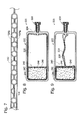
- Figs. 5-7 show generally, at 120, a second embodiment of a fuel supply according to the present invention.
- Fuel supply 120 includes an outer casing 122, an inner fuel container 124 enclosing a fuel storage area 126, a fuel outlet 128, and an inlet valve 130 typically configured to pass either air or fuel cell waste into the space between outer casing 122 and fuel storage area 124. Additionally, fuel supply 120 includes a backpressure regulator 140 for maintaining a slight backpressure at fuel outlet 128.
- the backpressure regulator 140 depicted in Figs. 5-7 takes the form of a capillary element 142 disposed in the wall of fuel container 124.
- capillary element 142 includes an opening 144 that opens into fuel container 124, allowing a small amount of fuel to be drawn into the capillary element by capillary action.
- the slight suction created by the capillary action creates a slightly reduced pressure inside of fuel storage area 124 relative to the outside environment, helping to prevent fuel from seeping out of fuel outlet 128 when the fuel cell is not in use.
- the material from which fuel container 124 is made may be chosen to achieve a desired degree of chemical interaction between the fuel and the fuel container, and thus to tailor the strength of the capillary interaction between the fuel solution and capillary element 142.
- suitable materials include polymers such as polyethylene, polypropylene, polysulfone, polyvinyl chloride, polyvinylidene, PET, PETE, and mixtures and/or copolymers thereof.
- the polymers may be filled with materials such as glass, talc, carbon, or a metal material such as aluminum, steel, brass, or other common metals or metal alloys.
- Capillary element 142 may have any suitable configuration that is capable of creating a backpressure via capillary action, and may include capillary structures positioned either inside or outside of fuel storage area 126.
- capillary element 142 may include a capillary structure contained within fuel storage area 126 floating freely in the fuel.
- capillary element 142 may include a capillary structure disposed within the space between outer container 122 and fuel container 124, where the structure has an opening to fuel storage area 126.
- capillary element 142 is a spiral-shaped tube formed in the wall of fuel container 124. It will be appreciated, of course, that capillary element 142 may take any of a variety of forms.
- Fig. 7 shows one possible construction of capillary element 142.
- fuel container 124 is formed from two layers of material, an inner layer 124 a and an outer layer 124 b .
- a first portion of capillary element 142 is molded into inner layer 124 a
- a second portion of capillary element is molded into outer layer 124 b .
- Capillary element 142 is thus formed by fusing or otherwise joining bottom layer 124 a to top layer 124 b .
- the use of a spiral shape allows capillary element 142 to be made a relatively long length in relation to the space taken by the capillary element in the wall of fuel container 124.
- a fuel supply according to the present invention may have any desired number of capillary elements without departing from the scope of the present invention.
- Capillary element 142 may also help to prevent fuel from seeping out of fuel outlet 128 during changes in atmospheric pressure.
- the pressure within capillary element 142 may be set at a level initially somewhat below atmospheric pressure.
- the lowered pressure in capillary element 142 will cause some fuel to be pushed into the capillary element to equalize the pressures inside of capillary element 142 and inside of fuel container 124. In this situation, capillary element 142 will be partially filled with fuel during ordinary use.
- the expansion or contraction of air within the unfilled portion of capillary element 142 may cause fuel to flow into or out of the capillary element to compensate for the pressure changes, rather than pushing fuel out of fuel outlet 128.
- Figs. 8 and 9 show generally, at 220, a third embodiment of a fuel supply according to the present invention.
- fuel supply 220 includes an outer container 222, an inner fuel container 224 that encloses a fuel storage area 226, a fuel outlet 228, and an inlet (not shown) typically for passing either air or fuel cell waste into the space between outer container 222 and inner fuel container 224.
- fuel supply 220 also includes a backpressure regulator 240 disposed within fuel container 224. In the embodiment of Figs. 8 and 9, however, backpressure regulator 240 takes the form of a foam element 242 in fluid communication with fuel contained within fuel storage area 226.
- Foam element 242 is typically formed at least partially from an open cell foam, and thus contains a plurality of narrow channels that act as capillaries to draw in fuel. This causes a slight suction that lowers the pressure within fuel container 224 relative to the pressure outside of fuel container 224, creating a backpressure at fuel outlet 228. Generally, at least some air must be present within foam element 242 to create the backpressure. This air could be provided by preloading foam element 242 with a certain amount of air during the manufacturing process.
- foam element 242 Any suitable type of foam may be used for foam element 242.
- the foam may be chosen based upon the desired degree of chemical interaction between the fuel and foam element 242 to tailor the magnitude of the capillary interaction between the fuel and the foam.
- suitable foams include polyurethane and polyamide.
- Foam element 242 may be fluidly connected to fuel storage area 226 in any desired manner.
- foam element 242 may be positioned within fuel container 224 such that it is in contact with fuel on multiple sides.
- one or more sides of foam element 242 are in direct contact with the inside wall of inner container 222. This seals the ends of some of the capillary channels created by the open-celled structure of foam element 242, and thus may trap some air within foam element 242, allowing fuel to flow into or out of the foam element to compensate for the pressure changes.
- foam element 242 is contained within a rear portion 244 of fuel container 224.
- Foam element 242 is separated from fuel storage area 226 by a divider 246.
- Divider 246 includes one or more channels 248 through which fuel may flow to reach foam element 242.
- Channels 248 may be configured to draw fuel toward foam element 242 by capillary action, or may be large enough to allow fuel to flow freely into contact with the foam element.
- Fuel supply 220 Operation of fuel supply 220 is also shown in Figs. 8-9.
- fuel storage area 226 decreases in volume.
- foam element 242 will typically resist collapse as fuel is withdrawn from fuel storage area 226. Therefore, the volume and shape of rear portion 244 of fuel container 224 may remain generally unchanged during the collapse of fuel storage area 226.
- foam element 242 may also help to prevent fuel from seeping out of fuel outlet 128 during changes in atmospheric pressure.
- the pressure within foam element 242 may be set at a level initially somewhat below atmospheric pressure.
- the lowered pressure in foam element 242 will cause some fuel to be pushed into the foam element to equalize the pressures inside of foam element 242 and inside of fuel container 224. In this situation, foam element 242 will be partially filled with fuel during ordinary use. If the atmospheric pressure increases or decreases during the lifetime of the fuel supply, the expansion or contraction of air within the unfilled portion of foam element 242 may cause fuel to flow into or out of the foam element to compensate for the pressure changes, rather than pushing air out of fuel outlet 228.
Landscapes
- Life Sciences & Earth Sciences (AREA)
- Engineering & Computer Science (AREA)
- Manufacturing & Machinery (AREA)
- Sustainable Development (AREA)
- Sustainable Energy (AREA)
- Chemical & Material Sciences (AREA)
- Chemical Kinetics & Catalysis (AREA)
- Electrochemistry (AREA)
- General Chemical & Material Sciences (AREA)
- Fuel Cell (AREA)
Applications Claiming Priority (2)
| Application Number | Priority Date | Filing Date | Title |
|---|---|---|---|
| US10/056,175 US6808833B2 (en) | 2002-01-22 | 2002-01-22 | Fuel supply for a fuel cell |
| US56175 | 2002-01-22 |
Publications (3)
| Publication Number | Publication Date |
|---|---|
| EP1331684A2 true EP1331684A2 (de) | 2003-07-30 |
| EP1331684A3 EP1331684A3 (de) | 2005-09-14 |
| EP1331684B1 EP1331684B1 (de) | 2008-11-26 |
Family
ID=22002668
Family Applications (1)
| Application Number | Title | Priority Date | Filing Date |
|---|---|---|---|
| EP03250086A Expired - Lifetime EP1331684B1 (de) | 2002-01-22 | 2003-01-08 | Brennstoffversorgung für eine Brennstoffzelle |
Country Status (5)
| Country | Link |
|---|---|
| US (1) | US6808833B2 (de) |
| EP (1) | EP1331684B1 (de) |
| JP (1) | JP3950065B2 (de) |
| DE (1) | DE60324850D1 (de) |
| TW (1) | TWI260102B (de) |
Cited By (3)
| Publication number | Priority date | Publication date | Assignee | Title |
|---|---|---|---|---|
| WO2005045967A3 (en) * | 2003-10-31 | 2005-12-01 | Hewlett Packard Development Co | Method and apparatus for fueling fuel cells |
| WO2006049265A3 (en) * | 2004-11-01 | 2008-02-21 | Casio Computer Co Ltd | Fuel container |
| CN101416337B (zh) * | 2004-11-01 | 2012-06-27 | 卡西欧计算机株式会社 | 燃料容器 |
Families Citing this family (58)
| Publication number | Priority date | Publication date | Assignee | Title |
|---|---|---|---|---|
| US6828049B2 (en) * | 2001-10-29 | 2004-12-07 | Hewlett-Packard Development Company, L.P. | Replaceable fuel cell apparatus having information storage device |
| US6713201B2 (en) * | 2001-10-29 | 2004-03-30 | Hewlett-Packard Development Company, L.P. | Systems including replaceable fuel cell apparatus and methods of using replaceable fuel cell apparatus |
| US6887596B2 (en) | 2002-01-22 | 2005-05-03 | Hewlett-Packard Development Company, L.P. | Portable disposable fuel-battery unit for a fuel cell system |
| US20030138679A1 (en) * | 2002-01-22 | 2003-07-24 | Ravi Prased | Fuel cartridge and reaction chamber |
| JP3841012B2 (ja) * | 2002-04-15 | 2006-11-01 | 日本電気株式会社 | 燃料電池、電気機器、および電気機器の駆動方法 |
| US7097813B2 (en) * | 2002-06-21 | 2006-08-29 | Hewlett-Packard Development Company, L.P. | Hydrogen generating apparatus |
| US7731491B2 (en) * | 2002-10-16 | 2010-06-08 | Hewlett-Packard Development Company, L.P. | Fuel storage devices and apparatus including the same |
| DE10305310B4 (de) * | 2003-02-10 | 2005-11-24 | Robert Bosch Gmbh | Vorrichtung zur Dämpfung von Druckpulsationen |
| US20040173615A1 (en) * | 2003-03-07 | 2004-09-09 | Goodman John B. | Fuel storage container for a fuel cell |
| US20050019641A1 (en) * | 2003-06-18 | 2005-01-27 | Toshiyuki Aoyama | Fuel tank for fuel-cell and fuel cell system |
| US20060127711A1 (en) * | 2004-06-25 | 2006-06-15 | Ultracell Corporation, A California Corporation | Systems and methods for fuel cartridge distribution |
| WO2005004258A2 (en) * | 2003-06-27 | 2005-01-13 | Ultracell Corporation | Portable fuel cartridge for fuel cells |
| US8613297B2 (en) * | 2003-07-29 | 2013-12-24 | Societe Bic | Fuel supply systems having operational resistance |
| US7172825B2 (en) * | 2003-07-29 | 2007-02-06 | Societe Bic | Fuel cartridge with flexible liner containing insert |
| JP2005108812A (ja) * | 2003-09-12 | 2005-04-21 | Sanyo Electric Co Ltd | 燃料タンク |
| JP3989471B2 (ja) | 2003-09-12 | 2007-10-10 | 三洋電機株式会社 | 燃料電池装置 |
| JP2005108559A (ja) * | 2003-09-29 | 2005-04-21 | Casio Comput Co Ltd | 燃料容器 |
| US7489859B2 (en) * | 2003-10-09 | 2009-02-10 | Hewlett-Packard Development Company, L.P. | Fuel storage devices and apparatus including the same |
| US7117732B2 (en) * | 2003-12-01 | 2006-10-10 | Societe Bic | Fuel gauge for fuel cartridges |
| US7655331B2 (en) | 2003-12-01 | 2010-02-02 | Societe Bic | Fuel cell supply including information storage device and control system |
| CN100499233C (zh) * | 2004-01-23 | 2009-06-10 | 日本电气株式会社 | 用于燃料电池的燃料盒以及使用该燃料盒的燃料电池 |
| KR100536200B1 (ko) * | 2004-01-26 | 2005-12-12 | 삼성에스디아이 주식회사 | 연료 전지 시스템 |
| US7670706B2 (en) | 2004-04-07 | 2010-03-02 | Panasonic Corporation | Fuel cartridge for fuel cell, and fuel cell |
| US8084150B2 (en) * | 2004-04-28 | 2011-12-27 | Eveready Battery Company, Inc. | Fuel cartridges and apparatus including the same |
| WO2005110299A2 (en) * | 2004-05-07 | 2005-11-24 | Ardica Technologies, Inc. | A method of controlling body temperature with an electrochemical device while providing on-demand power to an electrical device |
| US7648792B2 (en) | 2004-06-25 | 2010-01-19 | Ultracell Corporation | Disposable component on a fuel cartridge and for use with a portable fuel cell system |
| US7968250B2 (en) | 2004-06-25 | 2011-06-28 | Ultracell Corporation | Fuel cartridge connectivity |
| JP2006049032A (ja) * | 2004-08-03 | 2006-02-16 | Nidec Sankyo Corp | 燃料カートリッジ及び燃料電池システム |
| US7894174B2 (en) * | 2004-08-23 | 2011-02-22 | Monolithic Power Systems, Inc. | Method and apparatus for fault detection scheme for cold cathode fluorescent lamp (CCFL) integrated circuits |
| WO2006060546A2 (en) * | 2004-12-01 | 2006-06-08 | Cook Incorporated | Valve with leak path |
| US20060204802A1 (en) * | 2005-03-10 | 2006-09-14 | Specht Steven J | Fuel cell systems and related methods |
| KR101536331B1 (ko) * | 2005-07-18 | 2015-07-14 | 인텔리전트 에너지 리미티드 | 분리가능한 연료 공급원 |
| US8795926B2 (en) | 2005-08-11 | 2014-08-05 | Intelligent Energy Limited | Pump assembly for a fuel cell system |
| US8187758B2 (en) * | 2005-08-11 | 2012-05-29 | Ardica Technologies Inc. | Fuel cell apparatus with a split pump |
| US20070036711A1 (en) * | 2005-08-11 | 2007-02-15 | Ardica Technologies Inc. | Hydrogen generator |
| US7779856B2 (en) * | 2005-10-05 | 2010-08-24 | Societe Bic | Fuel cartridge of a fuel cell with fuel stored outside fuel liner |
| US8512911B2 (en) * | 2005-10-25 | 2013-08-20 | Societe Bic | Fuel supply systems having operational resistance |
| JP5063935B2 (ja) * | 2006-06-02 | 2012-10-31 | 東洋製罐株式会社 | 燃料電池カートリッジ用ポリエステル製容器 |
| US8286464B2 (en) * | 2006-12-22 | 2012-10-16 | Societe Bic | Sensing device and methods related thereto |
| ES2504215T3 (es) * | 2007-03-21 | 2014-10-08 | SOCIéTé BIC | Colector de fluido y procedimiento para el mismo |
| US8133629B2 (en) | 2007-03-21 | 2012-03-13 | SOCIéTé BIC | Fluidic distribution system and related methods |
| JP2009070594A (ja) * | 2007-09-11 | 2009-04-02 | Panasonic Corp | 燃料供給アダプタ装置および燃料供給装置 |
| JP2009117268A (ja) * | 2007-11-09 | 2009-05-28 | Panasonic Corp | 燃料供給装置 |
| CN101453818B (zh) | 2007-11-29 | 2014-03-19 | 杭州茂力半导体技术有限公司 | 放电灯的电路保护和调节装置 |
| US9034531B2 (en) | 2008-01-29 | 2015-05-19 | Ardica Technologies, Inc. | Controller for fuel cell operation |
| JP2011511416A (ja) * | 2008-01-29 | 2011-04-07 | アーディカ テクノロジーズ インコーポレイテッド | 燃料電池アノードから非燃料物質をパージするためのシステム |
| RU2393376C2 (ru) * | 2008-08-27 | 2010-06-27 | Сергей Владимирович ЛУКЬЯНЕЦ | Баллон высокого давления |
| US20100053852A1 (en) * | 2008-09-02 | 2010-03-04 | Cheng Uei Precision Industry Co., Ltd. | Display Device |
| US8808410B2 (en) | 2009-07-23 | 2014-08-19 | Intelligent Energy Limited | Hydrogen generator and product conditioning method |
| US8741004B2 (en) | 2009-07-23 | 2014-06-03 | Intelligent Energy Limited | Cartridge for controlled production of hydrogen |
| US20110020215A1 (en) * | 2009-07-23 | 2011-01-27 | Ryu Wonhyoung | Chemical hydride formulation and system design for controlled generation of hydrogen |
| US20110053016A1 (en) * | 2009-08-25 | 2011-03-03 | Daniel Braithwaite | Method for Manufacturing and Distributing Hydrogen Storage Compositions |
| WO2011097198A1 (en) * | 2010-02-08 | 2011-08-11 | Eveready Battery Company, Inc. | Fuel cell cartridge |
| US8940458B2 (en) | 2010-10-20 | 2015-01-27 | Intelligent Energy Limited | Fuel supply for a fuel cell |
| WO2013009379A1 (en) | 2011-07-11 | 2013-01-17 | Eveready Battery Company, Inc. | Gas generator with combined gas flow valve and pressure relief vent |
| US9169976B2 (en) | 2011-11-21 | 2015-10-27 | Ardica Technologies, Inc. | Method of manufacture of a metal hydride fuel supply |
| JP6601425B2 (ja) * | 2017-01-18 | 2019-11-06 | トヨタ自動車株式会社 | ガスタンク用のライナーおよびガスタンク |
| KR102739165B1 (ko) * | 2018-12-11 | 2024-12-06 | 현대자동차주식회사 | 연료전지 시스템의 배기압력조절장치 |
Family Cites Families (15)
| Publication number | Priority date | Publication date | Assignee | Title |
|---|---|---|---|---|
| US4771295B1 (en) * | 1986-07-01 | 1995-08-01 | Hewlett Packard Co | Thermal ink jet pen body construction having improved ink storage and feed capability |
| US4791438A (en) * | 1987-10-28 | 1988-12-13 | Hewlett-Packard Company | Balanced capillary ink jet pen for ink jet printing systems |
| US4794409A (en) * | 1987-12-03 | 1988-12-27 | Hewlett-Packard Company | Ink jet pen having improved ink storage and distribution capabilities |
| US5010354A (en) * | 1989-11-28 | 1991-04-23 | Hewlett-Packard Company | Ink jet pen with improved volumetric efficiency |
| US6041762A (en) * | 1996-08-16 | 2000-03-28 | Impco Technologies, Inc. | Control module for natural gas fuel supply for a vehicle |
| US5969736A (en) * | 1998-07-14 | 1999-10-19 | Hewlett-Packard Company | Passive pressure regulator for setting the pressure of a liquid to a predetermined pressure differential below a reference pressure |
| DE19913977C2 (de) * | 1999-03-18 | 2001-11-22 | Mannesmann Ag | Kraftstoffbehälter |
| JP3668069B2 (ja) * | 1999-09-21 | 2005-07-06 | 株式会社東芝 | 燃料電池用液体燃料収容容器および燃料電池 |
| WO2001045189A1 (en) * | 1999-12-17 | 2001-06-21 | The Regents Of The University Of California | Passive air breathing direct methanol fuel cell |
| WO2001075999A1 (en) * | 2000-03-30 | 2001-10-11 | Manhattan Scientifics, Inc. | Diffusion fuel ampoules for fuel cells |
| JP2001313047A (ja) * | 2000-04-28 | 2001-11-09 | Yuasa Corp | 直接メタノール型燃料電池 |
| US6447945B1 (en) * | 2000-12-12 | 2002-09-10 | General Atomics | Portable electronic device powered by proton exchange membrane fuel cell |
| US6460733B2 (en) * | 2001-02-20 | 2002-10-08 | Mti Microfuel Cells, Inc. | Multiple-walled fuel container and delivery system |
| WO2002099916A2 (en) | 2001-06-01 | 2002-12-12 | Polyfuel, Inc | Fuel cell assembly for portable electronic device and interface, control, and regulator circuit for fuel cell powered electronic device |
| EP1313160A1 (de) | 2001-11-13 | 2003-05-21 | SFC Smart Fuel Cell AG | Vorrichtung zur Brennstoffversorgung von Brennstoffzellen |
-
2002
- 2002-01-22 US US10/056,175 patent/US6808833B2/en not_active Expired - Lifetime
- 2002-11-19 TW TW091133737A patent/TWI260102B/zh not_active IP Right Cessation
-
2003
- 2003-01-08 EP EP03250086A patent/EP1331684B1/de not_active Expired - Lifetime
- 2003-01-08 DE DE60324850T patent/DE60324850D1/de not_active Expired - Lifetime
- 2003-01-22 JP JP2003013589A patent/JP3950065B2/ja not_active Expired - Fee Related
Cited By (5)
| Publication number | Priority date | Publication date | Assignee | Title |
|---|---|---|---|---|
| WO2005045967A3 (en) * | 2003-10-31 | 2005-12-01 | Hewlett Packard Development Co | Method and apparatus for fueling fuel cells |
| US7572536B2 (en) | 2003-10-31 | 2009-08-11 | Hewlett-Packard Development Company, L.P. | Method and apparatus for fueling fuel cells |
| WO2006049265A3 (en) * | 2004-11-01 | 2008-02-21 | Casio Computer Co Ltd | Fuel container |
| US7687178B2 (en) | 2004-11-01 | 2010-03-30 | Casio Computer Co., Ltd. | Fuel container |
| CN101416337B (zh) * | 2004-11-01 | 2012-06-27 | 卡西欧计算机株式会社 | 燃料容器 |
Also Published As
| Publication number | Publication date |
|---|---|
| JP3950065B2 (ja) | 2007-07-25 |
| US20030136453A1 (en) | 2003-07-24 |
| DE60324850D1 (de) | 2009-01-08 |
| EP1331684A3 (de) | 2005-09-14 |
| EP1331684B1 (de) | 2008-11-26 |
| TWI260102B (en) | 2006-08-11 |
| JP2003217618A (ja) | 2003-07-31 |
| US6808833B2 (en) | 2004-10-26 |
| TW200302595A (en) | 2003-08-01 |
Similar Documents
| Publication | Publication Date | Title |
|---|---|---|
| US6808833B2 (en) | Fuel supply for a fuel cell | |
| US7147955B2 (en) | Fuel cartridge for fuel cells | |
| KR101307832B1 (ko) | 가요성 라이너를 구비한 연료 카트리지 | |
| EP1306917B1 (de) | Brennstoffzuführung für Brenstoffzelle | |
| CN1998106B (zh) | 燃料电池的燃料盒及其制造方法 | |
| US20050115637A1 (en) | Method and apparatus for filling a fuel container | |
| HK1054618A (en) | Fuel supply for a fuel cell |
Legal Events
| Date | Code | Title | Description |
|---|---|---|---|
| PUAI | Public reference made under article 153(3) epc to a published international application that has entered the european phase |
Free format text: ORIGINAL CODE: 0009012 |
|
| AK | Designated contracting states |
Designated state(s): AT BE BG CH CY CZ DE DK EE ES FI FR GB GR HU IE IT LI LU MC NL PT SE SI SK TR |
|
| AX | Request for extension of the european patent |
Extension state: AL LT LV MK RO |
|
| PUAL | Search report despatched |
Free format text: ORIGINAL CODE: 0009013 |
|
| AK | Designated contracting states |
Kind code of ref document: A3 Designated state(s): AT BE BG CH CY CZ DE DK EE ES FI FR GB GR HU IE IT LI LU MC NL PT SE SI SK TR |
|
| AX | Request for extension of the european patent |
Extension state: AL LT LV MK RO |
|
| 17P | Request for examination filed |
Effective date: 20060217 |
|
| AKX | Designation fees paid |
Designated state(s): DE FR GB |
|
| GRAP | Despatch of communication of intention to grant a patent |
Free format text: ORIGINAL CODE: EPIDOSNIGR1 |
|
| GRAS | Grant fee paid |
Free format text: ORIGINAL CODE: EPIDOSNIGR3 |
|
| GRAA | (expected) grant |
Free format text: ORIGINAL CODE: 0009210 |
|
| AK | Designated contracting states |
Kind code of ref document: B1 Designated state(s): DE FR GB |
|
| REG | Reference to a national code |
Ref country code: GB Ref legal event code: FG4D |
|
| REF | Corresponds to: |
Ref document number: 60324850 Country of ref document: DE Date of ref document: 20090108 Kind code of ref document: P |
|
| PLBE | No opposition filed within time limit |
Free format text: ORIGINAL CODE: 0009261 |
|
| STAA | Information on the status of an ep patent application or granted ep patent |
Free format text: STATUS: NO OPPOSITION FILED WITHIN TIME LIMIT |
|
| 26N | No opposition filed |
Effective date: 20090827 |
|
| REG | Reference to a national code |
Ref country code: HK Ref legal event code: WD Ref document number: 1054618 Country of ref document: HK |
|
| REG | Reference to a national code |
Ref country code: GB Ref legal event code: 732E Free format text: REGISTERED BETWEEN 20101223 AND 20101229 |
|
| REG | Reference to a national code |
Ref country code: FR Ref legal event code: TP |
|
| REG | Reference to a national code |
Ref country code: DE Ref legal event code: R081 Ref document number: 60324850 Country of ref document: DE Owner name: EVEREADY BATTERY CO., INC., ST. LOUIS, US Free format text: FORMER OWNER: HEWLETT-PACKARD DEVELOPMENT COMPANY, L.P., HOUSTON, TEX., US Effective date: 20110210 |
|
| REG | Reference to a national code |
Ref country code: DE Ref legal event code: R082 Ref document number: 60324850 Country of ref document: DE |
|
| REG | Reference to a national code |
Ref country code: FR Ref legal event code: PLFP Year of fee payment: 14 |
|
| PGFP | Annual fee paid to national office [announced via postgrant information from national office to epo] |
Ref country code: DE Payment date: 20160127 Year of fee payment: 14 |
|
| PGFP | Annual fee paid to national office [announced via postgrant information from national office to epo] |
Ref country code: FR Payment date: 20160126 Year of fee payment: 14 Ref country code: GB Payment date: 20160127 Year of fee payment: 14 |
|
| REG | Reference to a national code |
Ref country code: DE Ref legal event code: R119 Ref document number: 60324850 Country of ref document: DE |
|
| GBPC | Gb: european patent ceased through non-payment of renewal fee |
Effective date: 20170108 |
|
| REG | Reference to a national code |
Ref country code: FR Ref legal event code: ST Effective date: 20170929 |
|
| PG25 | Lapsed in a contracting state [announced via postgrant information from national office to epo] |
Ref country code: FR Free format text: LAPSE BECAUSE OF NON-PAYMENT OF DUE FEES Effective date: 20170131 |
|
| PG25 | Lapsed in a contracting state [announced via postgrant information from national office to epo] |
Ref country code: GB Free format text: LAPSE BECAUSE OF NON-PAYMENT OF DUE FEES Effective date: 20170108 Ref country code: DE Free format text: LAPSE BECAUSE OF NON-PAYMENT OF DUE FEES Effective date: 20170801 |