EP1331121A2 - Verstellvorrichtung für ein Faltdach eines Fahrzeugs - Google Patents
Verstellvorrichtung für ein Faltdach eines Fahrzeugs Download PDFInfo
- Publication number
- EP1331121A2 EP1331121A2 EP02028203A EP02028203A EP1331121A2 EP 1331121 A2 EP1331121 A2 EP 1331121A2 EP 02028203 A EP02028203 A EP 02028203A EP 02028203 A EP02028203 A EP 02028203A EP 1331121 A2 EP1331121 A2 EP 1331121A2
- Authority
- EP
- European Patent Office
- Prior art keywords
- bearing
- toggle lever
- roof
- adjusting device
- control link
- Prior art date
- Legal status (The legal status is an assumption and is not a legal conclusion. Google has not performed a legal analysis and makes no representation as to the accuracy of the status listed.)
- Granted
Links
- 230000033001 locomotion Effects 0.000 claims description 19
- 238000006073 displacement reaction Methods 0.000 description 4
- 230000005540 biological transmission Effects 0.000 description 3
- 210000003127 knee Anatomy 0.000 description 3
- 238000006243 chemical reaction Methods 0.000 description 2
- 238000000034 method Methods 0.000 description 2
- 208000036829 Device dislocation Diseases 0.000 description 1
- 230000000903 blocking effect Effects 0.000 description 1
- 238000009434 installation Methods 0.000 description 1
Images





Classifications
-
- B—PERFORMING OPERATIONS; TRANSPORTING
- B60—VEHICLES IN GENERAL
- B60J—WINDOWS, WINDSCREENS, NON-FIXED ROOFS, DOORS, OR SIMILAR DEVICES FOR VEHICLES; REMOVABLE EXTERNAL PROTECTIVE COVERINGS SPECIALLY ADAPTED FOR VEHICLES
- B60J7/00—Non-fixed roofs; Roofs with movable panels, e.g. rotary sunroofs
- B60J7/185—Locking arrangements
- B60J7/1858—Locking arrangements for locking soft tops to a surrounding rigid roof structure, e.g. to a closed vehicle body
-
- B—PERFORMING OPERATIONS; TRANSPORTING
- B60—VEHICLES IN GENERAL
- B60J—WINDOWS, WINDSCREENS, NON-FIXED ROOFS, DOORS, OR SIMILAR DEVICES FOR VEHICLES; REMOVABLE EXTERNAL PROTECTIVE COVERINGS SPECIALLY ADAPTED FOR VEHICLES
- B60J7/00—Non-fixed roofs; Roofs with movable panels, e.g. rotary sunroofs
- B60J7/02—Non-fixed roofs; Roofs with movable panels, e.g. rotary sunroofs of sliding type, e.g. comprising guide shoes
- B60J7/06—Non-fixed roofs; Roofs with movable panels, e.g. rotary sunroofs of sliding type, e.g. comprising guide shoes with non-rigid element or elements
- B60J7/061—Non-fixed roofs; Roofs with movable panels, e.g. rotary sunroofs of sliding type, e.g. comprising guide shoes with non-rigid element or elements sliding and folding
Definitions
- the invention relates to an adjusting device for opening and closing a Folding roof of a vehicle with a sliding on a roof-side guideway stored carriage, which with a movable roof part of the Folding roof is connected, and with a drive device, which by means of a a drive carriage mounted on the roof and one of a control link controlled and a toggle lever arrangement is connected to the bearing carriage, being on the last one Closing path the handlebar arrangement a reduction of the drive movement of the Executes drive carriage.
- EP 0 755 815 A1 shows a folding roof with such an adjustment device, in which a drive carriage slidably guided along a guideway via a toggle lever with a bow bracket of an end bow of the folding roof is coupled.
- An end section of the guideway pivots the toggle lever compared to the drive carriage when approaching the closed position.
- the pivoting of the toggle lever causes the drive movement to be reduced of the drive carriage. Air forces acting on the end bow can with the folding roof closed, over the toggle lever on the drive carriage and so that it can be transferred to the drive motor.
- the object of the invention is a locking device mentioned at the outset to create, with which the folding roof can be closed in a functionally reliable manner can be, especially in the closed position reaction forces on the drive should be avoided.
- This task is related to the above locking device an improved function according to the invention also solved in that the Roof part is movably mounted on the bearing slide by means of a bearing device and an adjustment movement of the bearing device from an additional control link is controlled. This allows an individual superimposed on the longitudinal displacement Pivotal movement can be transmitted to the roof part, which is the roof part when closing, for example from above against a seal on the cowl can press.
- the toggle lever is preferably pivotable with an intermediate lever connected to the drive carriage.
- the intermediate lever By means of the intermediate lever, the Possibilities of kinematic displacement and arrangement of the toggle lever in its functional positions.
- the toggle lever is in its closed position with an engagement surface on the control link and the swivel joint of the Swivel arm is on the toggle lever between the engagement surface and the intermediate lever bearing swivel joint arranged.
- the toggle lever In this locked position the toggle lever is in a dead center position with respect to the swivel arm and the support of the engagement surface, in which it is self-locking against forces acts that act on the bearing slide and the swivel arm from the roof part can.
- the engagement surface of the toggle lever is expediently formed in a circular arc and the control link is at the closed position of the toggle lever as a counter-engagement surface formed, in particular also circular.
- the toggle lever In its closed position, the toggle lever preferably lies against a stop at, in particular at its rear end opposite the engagement surface. This is the closed position or the self-locking dead center or over dead center position clearly defined.
- the swivel bearing of the swivel arm on the bearing slide is arranged clearly above the guideway of the drive carriage the balance of forces on the bearing slide, the swivel arm and the knee lever advantageous for the movement behavior of the adjusting device.
- the roof part by means of a bearing device on the bearing slide is movably mounted and an adjustment movement of the bearing device of An additional control link is controlled, one of the longitudinal displacement superimposed individual swivel movement are transferred to the roof part, the roof part during the closing process, for example, from above against a seal can press on the cowl.
- the bearing device has two links in a four-bar arrangement contains and one of the handlebars guided on the additional control link is.
- This handlebar can two engagement elements such. B. have rollers or sliders, which are performed on the additional control link.
- the adjustment device is basically suitable for all types of folding roofs, that close a roof opening in a fixed roof or a removable roof can.
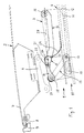
- An adjusting device 1 for opening and closing a folding roof 2 Vehicle e.g. B. a convertible, contains a bearing carriage 3, the one Guide track 4 of a guide rail 5 is slidably mounted on a lateral roof spar (not shown) of the vehicle is attached.
- the Longitudinal roof spar is, for example, part of a fixed roof frame Vehicle roofs with a roof opening that can be opened by the folding roof 2 close or at least partially open, or it is part of a from a closed position above a vehicle interior to an open position adjustable and convertible into a rear storage position, at which the side roof spars z. B. pivoted and with the roof in one rear compartment can be stored.
- the bearing slide 3 is firmly connected to a bearing plate 6 (connection not shown), on which a roof top 7 of the folding top 2 is firmly attached.
- the Roof top 7 is a front rigid element of the folding top 2 and contains its front edge has a seal 8 which, when the folding top 2 is closed (Fig. 1) close to a cowl 9 above a windshield of the vehicle is applied.
- the adjusting device 1 further includes a drive carriage 10 which is on a second guideway 11 slidably guided and with a drive cable 12 is connected, the z. B. from an electric drive motor in known Is driven in the opening and closing directions.
- the second track 11 is also formed on the guide rail 5 for the bearing slide 3 or attached or it is provided on an additional guide rail.
- a handlebar assembly having an intermediate lever 13 and a toggle lever 14 connects the drive carriage 10 with a swivel arm 15 which on the Bearing slide 3 is articulated in a swivel joint 16.
- the intermediate lever 13 is articulated on the one hand on the drive carriage 10 by means of a swivel joint 17 and on the other hand with the toggle lever 14 by means of a swivel joint 18 articulated.
- the end 19 opposite the swivel joint 18 the toggle lever 14 is disc-shaped and contains an outer engagement surface 20, which lies on a circular section with the center point 21.
- connection of the swivel arm 15 with the toggle lever 14 forms a swivel joint 22, the toggle lever 14 between the center 21 at the engagement end 19 and the opposite swivel joint 18 is arranged.
- the intermediate lever 13 and the toggle lever 14 are designed such that they are in the second guideway 11 together with the drive carriage 10 in the longitudinal direction are included (see Fig. 4) and can not swing out when it along the drive carriage 10 during the opening or closing movement the guide rail 5 are driven. This makes the bearing slide 3 via the swivel arm 15, the toggle lever 14 and the intermediate lever 13 in the opening and rigidly coupled to the drive carriage 10 in the closing direction.
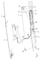
- the second guideway 11 is such open upwards that when the drive carriage moves forward 10 (movement from FIG. 4 to FIG. 3) first of all the toggle lever 14 with its Engagement end 19 emerges upwards and with its engagement surface 20 on one curved control link 23 slides along.
- the upward Swinging out of the toggle lever 14 takes place due to the forward facing Compressive force, which is introduced via the drive carriage 10 to the toggle lever 14 and the backward counterforce caused by the top tension on the bearing slide 3 and thus via the swivel joint 16 and the Swivel arm 15 is initiated on the swivel joint 22 on the toggle lever 14.
- the pivoting toggle lever 14 moves with its engagement end 19 to to a circular section-shaped support surface 24 of the control link 23 (FIG. 2) which engages the surface 20 of the toggle lever 14 against further upward displacement is blocked, but is pivotable in the blocking position.
- the Drive carriage 10 moved further now also pivots over the the intermediate lever 13 lifting the second guideway 11, the rear end 25 of the toggle lever 14 around the engagement end 19 held on the support surface 24 of the toggle lever 14, the front end 26 of the swivel arm 15 with the Swivel joint 22 is raised, but only a small horizontal Movement component executes.
- the drive carriage 10 remains during the pivoting movements of the intermediate lever 13 and the toggle lever 14 in its Guideway 11 out.
- the toggle lever 14 and / or the intermediate lever 13 In the front end position of the adjustment device (closed position according to Fig. 1) is the toggle lever 14 and / or the intermediate lever 13 in the area of their common Swivel joint 18 on a stop 27 which, for. B. on the guide rails 5 is formed.
- the toggle lever 14 is then aligned such that a connecting straight line 28 between the swivel joint 22 on the toggle lever 14 and the swivel joint 16 of the swivel arm 15 on the bearing slide 3 above the center 21 is arranged.
- the adjusting device 1 thus enables the drive to be fed at a constant rate and thus the drive cable 12 and the drive carriage 10 a reduction the feed movement of the bearing slide 3 and thus the roof tip 7 opposite the drive carriage 10 on the last closing path while at the same time the closing force is increased.
- a modified embodiment of the adjustment device described above contains a movable connection of the roof top 7 to the Bearing slide 3.
- the bearing plate 6 firmly connected to the roof top 7 mounted movably on the bearing slide 3 by means of a four-bar arrangement.
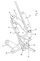
- the four-bar arrangement includes a front control lever 30 and a rear one Handlebar lever 31, which by means of first pivot joints 32 and 33 on the bearing plate 6 and by means of second swivel joints 34 and 35 on the bearing slide 3 are movably mounted.
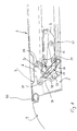
- control link 36 On the guide rail 5 is a second control link 36 attached or formed over almost the entire length of the guide rail 5 runs parallel to the guideway 4 of the bearing slide 3, however, at the front section of the guide rail 5 one against the guide track 11 has approximately curved guide section 37.
- the Control lever 30 is slidably engaged with this control link 36, for. B. by means of two engagement elements such as sliders or rollers 38 and 39, one Form gap between them in which the control link 36 is taken up without play is.
- the four-bar arrangement is such chosen and designed that the roof top 7 while moving along the guide rail 5 is raised relative to this and at the front section the guide rail 5 lowered towards the closed position (see Fig. 8) and is additionally pivoted downwards with its front edge, so that the Front edge pressed obliquely from above against a seal 40 on the cowl 9 becomes.
Landscapes
- Engineering & Computer Science (AREA)
- Mechanical Engineering (AREA)
- Power-Operated Mechanisms For Wings (AREA)
- Seal Device For Vehicle (AREA)
- Body Structure For Vehicles (AREA)
Abstract
Description
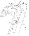
- Fig. 1
- in Seitenansicht in schematischer Darstellung ein erstes Ausführungsbeispiel einer Verstellvorrichtung mit einer Dachspitze eines Faltdaches eines Fahrzeugs in Schließstellung;
- Fig. 2
- in Seitenansicht in schematischer Darstellung die in Fig. 1 dargestellte Verstellvorrichtung beim Öffnungsvorgang;
- Fig. 3
- in Seitenansicht in schematischer Darstellung die gegenüber Fig. 2 weiter bewegte Verstellvorrichtung;
- Fig. 4
- in Seitenansicht in schematischer Darstellung die Verstellvorrichtung nach einer weiteren Öffnungsbewegung;
- Fig. 5
- in einer perspektivischen Seitenansicht eine zweite Ausführungsform der Verstellvorrichtung in einer Stellung entsprechend Fig. 2 der ersten Ausführungsform;
- Fig. 6
- in einer perspektivischen Seitenansicht die zweite Ausführungsform der Verstellvorrichtung in einer Zwischenstellung beim Öffnen der Dachspitze;
- Fig. 7
- in einer perspektivischen Seitenansicht die zweite Ausführungsform der Verstellvorrichtung in einer weiteren Zwischenstellung beim Öffnen der Dachspitze;
- Fig. 8
- in einer Seitenansicht in schematischer Darstellung die zweite Ausführungsform der Verstellvorrichtung in Schließstellung gemäß Fig. 1;
- Fig. 9
- in einer Seitenansicht in schematischer Darstellung die zweite Ausführungsform der Verstellvorrichtung in einer Stellung gemäß Fig. 6; und
- Fig. 10
- in einer perspektivischen Innenansicht die zweite Ausführungsform der Verstellvorrichtung in einer Stellung gemäß Fig. 6.
- 1
- Verstellvorrichtung
- 2
- Faltdach
- 3
- Lagerschlitten
- 4
- Führungsbahn
- 5
- Führungsschiene
- 6
- Lagerplatte
- 7
- Dachspitze
- 8
- Dichtung
- 9
- Windlauf
- 10
- Antriebsschlitten
- 11
- zweite Führungsbahn
- 12
- Antriebskabel
- 13
- Zwischenhebel
- 14
- Kniehebel
- 15
- Schwenkarm
- 16
- Schwenkgelenk
- 17
- Schwenkgelenk
- 18
- Schwenkgelenk
- 19
- Ende
- 20
- Eingriffsfläche
- 21
- Mittelpunkt
- 22
- Schwenkgelenk
- 23
- Steuerkulisse
- 24
- Abstützfläche
- 25
- Hinterende
- 26
- Vorderende
- 27
- Anschlag
- 28
- Verbindungsgerade
- 29 30
- vorderer Steuerhebel
- 31
- hinterer Lenkerhebel
- 32
- Schwenkgelenk
- 33
- Schwenkgelenk
- 34
- Schwenkgelenk
- 35
- Schwenkgelenk
- 36
- zweite Steuerkulisse
- 37
- Führungsabschnitt
- 38
- Rolle
- 39
- Rolle
- 40
- Dichtung
Claims (12)
- Verstellvorrichtung zum Öffnen und Schließen eines Faltdaches eines Fahrzeugs mit einem an einer dachseitigen Führungsbahn verschiebbar gelagerten Lagerschlitten, der mit einem bewegbaren Dachteil des Faltdachs verbunden ist, und mit einer Antriebseinrichtung, die mittels eines an einer dachseitigen Führungsbahn gelagerten Antriebsschlittens und einer von einer Steuerkulisse gesteuerten und einen Kniehebel aufweisenden Lenkeranordnung mit dem Lagerschlitten verbunden ist, wobei auf dem letzten Schließweg die Lenkeranordnung eine Untersetzung der Antriebsbewegung des Antriebsschlittens ausführt,
dadurch gekennzeichnet, daß der Kniehebel (14) der Lenkeranordnung, der mit einem Schwenkarm (15) des Lagerschlittens (3) schwenkbar verbunden ist, entlang der Steuerkulisse (23) in seine Schließstellung bewegbar ist, in der er selbsthemmend bezüglich einer am Lagerschlitten (3) über das Dachteil (7) wirkenden Öffnungskraft angeordnet ist. - Verstellvorrichtung nach dem Oberbegriff des Anspruchs 1,
dadurch gekennzeichnet, daß das Dachteil (7) mittels einer Lagereinrichtung (30, 31) am Lagerschlitten (3) bewegbar gelagert ist und eine Verstellbewegung der Lagereinrichtung (30, 31) von einer zusätzlichen Steuerkulisse (36, 37) gesteuert ist. - Verstellvorrichtung nach Anspruch 2,
dadurch gekennzeichnet, daß der Kniehebel (14) der Lenkeranordnung, der mit einem Schwenkarm (15) des Lagerschlittens (3) schwenkbar verbunden ist, entlang der Steuerkulisse (23) in seine Schließstellung bewegbar ist, in der er selbsthemmend bezüglich einer am Lagerschlitten (3) über das Dachteil (7) wirkenden Öffnungskraft angeordnet ist. - Verstellvorrichtung nach Anspruch 1 oder 3,
dadurch gekennzeichnet, daß der Kniehebel (14) mittels eines Zwischenhebels (13) schwenkbar mit dem Antriebsschlitten (10) verbunden ist. - Verstellvorrichtung nach einem der Ansprüche 1 bis 4,
dadurch gekennzeichnet, daß der Kniehebel (14) in seiner Schließstellung mit einer Eingriffsfläche (20) an der Steuerkulisse (23) anliegt und das Schwenkgelenk (22) des Schwenkarms (15) am Kniehebel (14) zwischen der Eingriffsfläche (20) und dem den Zwischenhebel (13) lagernden Schwenkgelenk (18) angeordnet ist. - Verstellvorrichtung nach Anspruch 5,
dadurch gekennzeichnet, daß die Eingriffsfläche (20) des Kniehebels (14) kreisbogenförmig gebildet ist und die Steuerkulisse (23) an der Schließposition des Kniehebels (14) als Gegeneingriffsfläche (24) gebildet ist. - Verstellvorrichtung nach einem der Ansprüche 1 bis 6,
dadurch gekennzeichnet, daß der Kniehebel (14) in seiner Schließposition an einem Anschlag (27) anliegt, insbesondere an seinem der Eingriffsfläche (20) gegenüberliegenden Hinterende (25). - Verstellvorrichtung nach einem der Ansprüche 4 bis 7,
dadurch gekennzeichnet, daß der Kniehebel (14) und der Zwischenhebel (13) an einer die Führungsbahn (11) enthaltenden Führungsschiene (5) über den wesentlichen Verstellweg unverschwenkbar geführt sind und lediglich bei Annäherung an die Schließstellung durch Steuerung mittels der Steuerkulisse (23) von der Führungsbahn (11) ausschwenken können. - Verstellvorrichtung nach einem der Ansprüche 1 bis 8,
dadurch gekennzeichnet, daß das Schwenklager (16) des Schwenkarms (15) am Lagerschlitten (3) oberhalb der Führungsbahn (11) des Antriebsschlittens (10) angeordnet ist. - Verstellvorrichtung nach einem der Ansprüche 1 bis 9,
dadurch gekennzeichnet, daß das Dachteil (7) mittels einer Lagereinrichtung (30, 31) am Lagerschlitten (3) bewegbar gelagert ist und eine Verstellbewegung der Lagereinrichtung (30, 31) von einer zusätzlichen Steuerkulisse (36, 37) gesteuert ist. - Verstellvorrichtung nach Anspruch 10,
dadurch gekennzeichnet, daß die Lagereinrichtung (30, 31) zwei Lenker (30, 31) in Viergelenkanordnung enthält und einer der Lenker (30) an der zusätzlichen Steuerkulisse (36, 37) geführt ist. - Verstellvorrichtung nach Anspruch 11,
dadurch gekennzeichnet, daß der Lenker (30) zwei Eingriffselemente (38, 39) aufweist, die an der zusätzlichen Steuerkulisse (36, 37) geführt sind.
Applications Claiming Priority (2)
| Application Number | Priority Date | Filing Date | Title |
|---|---|---|---|
| DE10203204 | 2002-01-27 | ||
| DE10203204A DE10203204B4 (de) | 2002-01-27 | 2002-01-27 | Verstellvorrichtung für ein Faltdach eines Fahrzeugs |
Publications (3)
| Publication Number | Publication Date |
|---|---|
| EP1331121A2 true EP1331121A2 (de) | 2003-07-30 |
| EP1331121A3 EP1331121A3 (de) | 2005-02-09 |
| EP1331121B1 EP1331121B1 (de) | 2007-05-09 |
Family
ID=7713219
Family Applications (1)
| Application Number | Title | Priority Date | Filing Date |
|---|---|---|---|
| EP02028203A Expired - Lifetime EP1331121B1 (de) | 2002-01-27 | 2002-12-14 | Verstellvorrichtung für ein Faltdach eines Fahrzeugs |
Country Status (3)
| Country | Link |
|---|---|
| US (1) | US6820916B2 (de) |
| EP (1) | EP1331121B1 (de) |
| DE (2) | DE10203204B4 (de) |
Cited By (4)
| Publication number | Priority date | Publication date | Assignee | Title |
|---|---|---|---|---|
| DE202005009177U1 (de) * | 2005-06-10 | 2006-10-26 | Remis Gesellschaft für Entwicklung und Vertrieb von technischen Elementen mbH Köln | Fahrzeugdach-Schwenkhaube |
| US7758110B2 (en) | 2005-11-11 | 2010-07-20 | Webasto Ag | Displaceable roof part of an openable vehicle roof |
| EP2572912A3 (de) * | 2011-09-22 | 2015-07-15 | Magna Car Top Systems GmbH | Verschlusskinematik für ein öffnungsfähiges Faltdach |
| CN114929505A (zh) * | 2019-10-30 | 2022-08-19 | 埃维亚斯公司 | 包括集电器的电推进式车辆 |
Families Citing this family (9)
| Publication number | Priority date | Publication date | Assignee | Title |
|---|---|---|---|---|
| DE102006007815B3 (de) * | 2006-02-17 | 2007-10-25 | Webasto Ag | Fahrzeugdach |
| DE102006050874B4 (de) * | 2006-10-27 | 2010-11-18 | Webasto Ag | Öffenbares Fahrzeugdach mit Betätigungseinrichtung für ein Dachelement |
| DE102007010317B4 (de) * | 2007-03-02 | 2009-02-19 | Webasto Ag | Öffnungsfähiges Fahrzeugdach mit einer Betätigungseinrichtung für ein bewegbares Dachelement |
| DE102007047457B4 (de) | 2007-10-03 | 2009-09-24 | Webasto Ag | Verstellbares Dachteil eines öffnungsfähigen Fahrzeugdaches |
| DE502008001339D1 (de) | 2008-07-20 | 2010-10-28 | Webasto Ag | Öffnungsfähiges Fahrzeugdach mit einem verstellbaren Dachteil |
| DE102009048958B4 (de) * | 2009-10-10 | 2017-08-31 | Webasto-Edscha Cabrio GmbH | Steueranordnung für ein öffnungsfähiges Dachteil eines Kraftfahrzeugs |
| US9931921B2 (en) * | 2013-04-02 | 2018-04-03 | Bestop, Inc. | Soft front cockpit cover |
| DE102013216292B4 (de) * | 2013-08-16 | 2017-10-26 | Bos Gmbh & Co. Kg | Antriebssystem für einen beweglichen Dachteil eines Dachmoduls eines Kraftfahrzeugs |
| DE102024111959A1 (de) * | 2023-05-09 | 2024-11-14 | Webasto SE | Anordnung zum Bewegen eines Deckels für ein Fahrzeugdach und Fahrzeugdach |
Citations (1)
| Publication number | Priority date | Publication date | Assignee | Title |
|---|---|---|---|---|
| EP0755815A1 (de) | 1995-07-22 | 1997-01-29 | WEBASTO KAROSSERIESYSTEME GmbH | Faltdach für Fahrzeuge |
Family Cites Families (6)
| Publication number | Priority date | Publication date | Assignee | Title |
|---|---|---|---|---|
| US3981531A (en) * | 1975-09-15 | 1976-09-21 | General Motors Corporation | Vehicle body sunroof |
| JP2685182B2 (ja) * | 1987-05-22 | 1997-12-03 | アイシン精機株式会社 | サンルーフ装置 |
| US5092651A (en) * | 1990-08-03 | 1992-03-03 | General Motors Corporation | Sliding and tilting sunroof control mechanism |
| FR2797225B1 (fr) * | 1999-08-02 | 2002-06-07 | Webasto Systemes Carrosserie | Dispositif pour ouvrir ou fermer un panneau exterieur mobile de toit ouvrant entrebaillant et coulissant |
| DE19943769C1 (de) * | 1999-09-13 | 2001-02-01 | Webasto Vehicle Sys Int Gmbh | Führungsvorrichtung für einen vorderen Endspriegel eines Faltdaches eines Fahrzeugs |
| DE10023865C1 (de) * | 2000-05-16 | 2001-09-27 | Webasto Vehicle Sys Int Gmbh | Fahrzeugfaltverdeck |
-
2002
- 2002-01-27 DE DE10203204A patent/DE10203204B4/de not_active Expired - Fee Related
- 2002-12-14 DE DE50210114T patent/DE50210114D1/de not_active Expired - Lifetime
- 2002-12-14 EP EP02028203A patent/EP1331121B1/de not_active Expired - Lifetime
-
2003
- 2003-01-24 US US10/350,335 patent/US6820916B2/en not_active Expired - Lifetime
Patent Citations (1)
| Publication number | Priority date | Publication date | Assignee | Title |
|---|---|---|---|---|
| EP0755815A1 (de) | 1995-07-22 | 1997-01-29 | WEBASTO KAROSSERIESYSTEME GmbH | Faltdach für Fahrzeuge |
Cited By (4)
| Publication number | Priority date | Publication date | Assignee | Title |
|---|---|---|---|---|
| DE202005009177U1 (de) * | 2005-06-10 | 2006-10-26 | Remis Gesellschaft für Entwicklung und Vertrieb von technischen Elementen mbH Köln | Fahrzeugdach-Schwenkhaube |
| US7758110B2 (en) | 2005-11-11 | 2010-07-20 | Webasto Ag | Displaceable roof part of an openable vehicle roof |
| EP2572912A3 (de) * | 2011-09-22 | 2015-07-15 | Magna Car Top Systems GmbH | Verschlusskinematik für ein öffnungsfähiges Faltdach |
| CN114929505A (zh) * | 2019-10-30 | 2022-08-19 | 埃维亚斯公司 | 包括集电器的电推进式车辆 |
Also Published As
| Publication number | Publication date |
|---|---|
| EP1331121A3 (de) | 2005-02-09 |
| EP1331121B1 (de) | 2007-05-09 |
| DE10203204B4 (de) | 2006-09-21 |
| DE10203204A1 (de) | 2003-08-07 |
| US6820916B2 (en) | 2004-11-23 |
| DE50210114D1 (de) | 2007-06-21 |
| US20030155795A1 (en) | 2003-08-21 |
Similar Documents
| Publication | Publication Date | Title |
|---|---|---|
| EP1112879B1 (de) | Umwandelbares Fahrzeugdach | |
| DE10000002C2 (de) | Verriegelungsvorrichtung für ein Klappverdeck | |
| DE4445580C1 (de) | Hardtop-Fahrzeug | |
| EP1172243B1 (de) | Fahrzeugdach mit wenigstens einem oberhalb des festen Fahrzeugsdachs verschiebbaren Deckel | |
| DE10205144B4 (de) | Verriegelungsvorrichtung für ein Faltdach eines Fahrzeugs | |
| EP1223065B1 (de) | Fahrzeugdach | |
| WO2007079747A1 (de) | Fahrzeugdach mit einem oberhalb eines festen dachabschnitts verschiebbaren deckel | |
| EP1155890B1 (de) | Fahrzeugfaltverdeck | |
| EP1331121B1 (de) | Verstellvorrichtung für ein Faltdach eines Fahrzeugs | |
| DE102023112152A1 (de) | Anordnung zum Bewegen eines Deckels für ein Fahrzeugdach und Fahrzeugdach | |
| EP2129540B1 (de) | Öffnungsfähiges fahrzeugdach mit einer betätigungseinrichtung für ein bewegbares dachelement | |
| DE102005054297B4 (de) | Verstellbares Dachteil eines öffnungsfähigen Fahrzeugdaches | |
| DE19634324A1 (de) | Fahrzeugdach | |
| DE102021131573A1 (de) | Fahrzeugdachsystem mit einer Dachöffnung | |
| DE202007001217U1 (de) | Fahrzeugdach mit einem oberhalb des Daches verschiebbaren Dachteil | |
| DE102007047457B4 (de) | Verstellbares Dachteil eines öffnungsfähigen Fahrzeugdaches | |
| DE10218263B4 (de) | Verdeck für ein Cabriolet-Fahrzeug | |
| DE10331143B4 (de) | Fahrzeugdach mit einer Dachöffnung und einer bewegbaren Dachschließeinrichtung | |
| EP1798085B1 (de) | Fahrzeugdachsystem für ein Cabriolet | |
| DE102021202488B4 (de) | Antriebssystem für eine Spoilerdachanordnung eines Kraftfahrzeugs und Spoilerdachanordnung | |
| DE10261688B4 (de) | Fahrzeug mit Klappverdeck und Verdeckkastendeckel | |
| DE102007060364B4 (de) | Kraftfahrzeug mit einer separat beweglichen, eine Heckscheibe umfassenden Baueinheit | |
| DE102024116566A1 (de) | Kraftfahrzeug mit einem Dachsystem mit karosseriefesten Dachseitenholmen und einem längs der Dachseitenholme beweglich gelagerten Deckelelement | |
| EP2147814A1 (de) | Öffnungsfähiges Fahrzeugdach mit einem verstellbaren Dachteil | |
| DE102011016780A1 (de) | Lenkersteuerung eines Spannbügels |
Legal Events
| Date | Code | Title | Description |
|---|---|---|---|
| PUAI | Public reference made under article 153(3) epc to a published international application that has entered the european phase |
Free format text: ORIGINAL CODE: 0009012 |
|
| AK | Designated contracting states |
Designated state(s): AT BE BG CH CY CZ DE DK EE ES FI FR GB GR IE IT LI LU MC NL PT SE SI SK TR |
|
| AX | Request for extension of the european patent |
Extension state: AL LT LV MK RO |
|
| PUAL | Search report despatched |
Free format text: ORIGINAL CODE: 0009013 |
|
| AK | Designated contracting states |
Kind code of ref document: A3 Designated state(s): AT BE BG CH CY CZ DE DK EE ES FI FR GB GR IE IT LI LU MC NL PT SE SI SK TR |
|
| AX | Request for extension of the european patent |
Extension state: AL LT LV MK RO |
|
| 17P | Request for examination filed |
Effective date: 20050504 |
|
| AKX | Designation fees paid |
Designated state(s): DE GB |
|
| GRAP | Despatch of communication of intention to grant a patent |
Free format text: ORIGINAL CODE: EPIDOSNIGR1 |
|
| GRAS | Grant fee paid |
Free format text: ORIGINAL CODE: EPIDOSNIGR3 |
|
| GRAA | (expected) grant |
Free format text: ORIGINAL CODE: 0009210 |
|
| AK | Designated contracting states |
Kind code of ref document: B1 Designated state(s): DE GB |
|
| REG | Reference to a national code |
Ref country code: GB Ref legal event code: FG4D Free format text: NOT ENGLISH |
|
| GBT | Gb: translation of ep patent filed (gb section 77(6)(a)/1977) |
Effective date: 20070523 |
|
| REF | Corresponds to: |
Ref document number: 50210114 Country of ref document: DE Date of ref document: 20070621 Kind code of ref document: P |
|
| PLBE | No opposition filed within time limit |
Free format text: ORIGINAL CODE: 0009261 |
|
| STAA | Information on the status of an ep patent application or granted ep patent |
Free format text: STATUS: NO OPPOSITION FILED WITHIN TIME LIMIT |
|
| 26N | No opposition filed |
Effective date: 20080212 |
|
| PGFP | Annual fee paid to national office [announced via postgrant information from national office to epo] |
Ref country code: GB Payment date: 20151221 Year of fee payment: 14 |
|
| GBPC | Gb: european patent ceased through non-payment of renewal fee |
Effective date: 20161214 |
|
| PG25 | Lapsed in a contracting state [announced via postgrant information from national office to epo] |
Ref country code: GB Free format text: LAPSE BECAUSE OF NON-PAYMENT OF DUE FEES Effective date: 20161214 |
|
| PGFP | Annual fee paid to national office [announced via postgrant information from national office to epo] |
Ref country code: DE Payment date: 20191217 Year of fee payment: 18 |
|
| REG | Reference to a national code |
Ref country code: DE Ref legal event code: R119 Ref document number: 50210114 Country of ref document: DE |
|
| PG25 | Lapsed in a contracting state [announced via postgrant information from national office to epo] |
Ref country code: DE Free format text: LAPSE BECAUSE OF NON-PAYMENT OF DUE FEES Effective date: 20210701 |