EP1331031A2 - Vorrichtung zur Erzeugung vom medizinischem Schaum - Google Patents
Vorrichtung zur Erzeugung vom medizinischem Schaum Download PDFInfo
- Publication number
- EP1331031A2 EP1331031A2 EP03001079A EP03001079A EP1331031A2 EP 1331031 A2 EP1331031 A2 EP 1331031A2 EP 03001079 A EP03001079 A EP 03001079A EP 03001079 A EP03001079 A EP 03001079A EP 1331031 A2 EP1331031 A2 EP 1331031A2
- Authority
- EP
- European Patent Office
- Prior art keywords
- foam
- foam nozzle
- liquid
- housing
- nozzle
- Prior art date
- Legal status (The legal status is an assumption and is not a legal conclusion. Google has not performed a legal analysis and makes no representation as to the accuracy of the status listed.)
- Granted
Links
Images


Classifications
-
- B—PERFORMING OPERATIONS; TRANSPORTING
- B05—SPRAYING OR ATOMISING IN GENERAL; APPLYING FLUENT MATERIALS TO SURFACES, IN GENERAL
- B05B—SPRAYING APPARATUS; ATOMISING APPARATUS; NOZZLES
- B05B7/00—Spraying apparatus for discharge of liquids or other fluent materials from two or more sources, e.g. of liquid and air, of powder and gas
- B05B7/0018—Spraying apparatus for discharge of liquids or other fluent materials from two or more sources, e.g. of liquid and air, of powder and gas with devices for making foam
- B05B7/0025—Spraying apparatus for discharge of liquids or other fluent materials from two or more sources, e.g. of liquid and air, of powder and gas with devices for making foam with a compressed gas supply
-
- B—PERFORMING OPERATIONS; TRANSPORTING
- B01—PHYSICAL OR CHEMICAL PROCESSES OR APPARATUS IN GENERAL
- B01F—MIXING, e.g. DISSOLVING, EMULSIFYING OR DISPERSING
- B01F35/00—Accessories for mixers; Auxiliary operations or auxiliary devices; Parts or details of general application
- B01F35/71—Feed mechanisms
- B01F35/717—Feed mechanisms characterised by the means for feeding the components to the mixer
- B01F35/718—Feed mechanisms characterised by the means for feeding the components to the mixer using vacuum, under pressure in a closed receptacle or circuit system
-
- B—PERFORMING OPERATIONS; TRANSPORTING
- B01—PHYSICAL OR CHEMICAL PROCESSES OR APPARATUS IN GENERAL
- B01F—MIXING, e.g. DISSOLVING, EMULSIFYING OR DISPERSING
- B01F23/00—Mixing according to the phases to be mixed, e.g. dispersing or emulsifying
- B01F23/20—Mixing gases with liquids
- B01F23/23—Mixing gases with liquids by introducing gases into liquid media, e.g. for producing aerated liquids
- B01F23/235—Mixing gases with liquids by introducing gases into liquid media, e.g. for producing aerated liquids for making foam
-
- B—PERFORMING OPERATIONS; TRANSPORTING
- B01—PHYSICAL OR CHEMICAL PROCESSES OR APPARATUS IN GENERAL
- B01F—MIXING, e.g. DISSOLVING, EMULSIFYING OR DISPERSING
- B01F23/00—Mixing according to the phases to be mixed, e.g. dispersing or emulsifying
- B01F23/70—Pre-treatment of the materials to be mixed
- B01F23/708—Filtering materials
-
- B—PERFORMING OPERATIONS; TRANSPORTING
- B01—PHYSICAL OR CHEMICAL PROCESSES OR APPARATUS IN GENERAL
- B01F—MIXING, e.g. DISSOLVING, EMULSIFYING OR DISPERSING
- B01F25/00—Flow mixers; Mixers for falling materials, e.g. solid particles
- B01F25/30—Injector mixers
- B01F25/31—Injector mixers in conduits or tubes through which the main component flows
- B01F25/311—Injector mixers in conduits or tubes through which the main component flows for mixing more than two components; Devices specially adapted for generating foam
- B01F25/3111—Devices specially adapted for generating foam, e.g. air foam
- B01F25/31112—Devices specially adapted for generating foam, e.g. air foam with additional mixing means other than injector mixers, e.g. screen or baffles
-
- B—PERFORMING OPERATIONS; TRANSPORTING
- B01—PHYSICAL OR CHEMICAL PROCESSES OR APPARATUS IN GENERAL
- B01F—MIXING, e.g. DISSOLVING, EMULSIFYING OR DISPERSING
- B01F25/00—Flow mixers; Mixers for falling materials, e.g. solid particles
- B01F25/40—Static mixers
- B01F25/45—Mixers in which the materials to be mixed are pressed together through orifices or interstitial spaces, e.g. between beads
- B01F25/452—Mixers in which the materials to be mixed are pressed together through orifices or interstitial spaces, e.g. between beads characterised by elements provided with orifices or interstitial spaces
- B01F25/4523—Mixers in which the materials to be mixed are pressed together through orifices or interstitial spaces, e.g. between beads characterised by elements provided with orifices or interstitial spaces the components being pressed through sieves, screens or meshes which obstruct the whole diameter of the tube
-
- B—PERFORMING OPERATIONS; TRANSPORTING
- B01—PHYSICAL OR CHEMICAL PROCESSES OR APPARATUS IN GENERAL
- B01F—MIXING, e.g. DISSOLVING, EMULSIFYING OR DISPERSING
- B01F33/00—Other mixers; Mixing plants; Combinations of mixers
- B01F33/50—Movable or transportable mixing devices or plants
- B01F33/501—Movable mixing devices, i.e. readily shifted or displaced from one place to another, e.g. portable during use
- B01F33/5011—Movable mixing devices, i.e. readily shifted or displaced from one place to another, e.g. portable during use portable during use, e.g. hand-held
-
- B—PERFORMING OPERATIONS; TRANSPORTING
- B01—PHYSICAL OR CHEMICAL PROCESSES OR APPARATUS IN GENERAL
- B01F—MIXING, e.g. DISSOLVING, EMULSIFYING OR DISPERSING
- B01F35/00—Accessories for mixers; Auxiliary operations or auxiliary devices; Parts or details of general application
- B01F35/10—Maintenance of mixers
- B01F35/145—Washing or cleaning mixers not provided for in other groups in this subclass; Inhibiting build-up of material on machine parts using other means
- B01F35/146—Working under sterile conditions; Sterilizing the mixer or parts thereof
-
- B—PERFORMING OPERATIONS; TRANSPORTING
- B01—PHYSICAL OR CHEMICAL PROCESSES OR APPARATUS IN GENERAL
- B01F—MIXING, e.g. DISSOLVING, EMULSIFYING OR DISPERSING
- B01F35/00—Accessories for mixers; Auxiliary operations or auxiliary devices; Parts or details of general application
- B01F35/71—Feed mechanisms
- B01F35/712—Feed mechanisms for feeding fluids
-
- B—PERFORMING OPERATIONS; TRANSPORTING
- B01—PHYSICAL OR CHEMICAL PROCESSES OR APPARATUS IN GENERAL
- B01F—MIXING, e.g. DISSOLVING, EMULSIFYING OR DISPERSING
- B01F35/00—Accessories for mixers; Auxiliary operations or auxiliary devices; Parts or details of general application
- B01F35/71—Feed mechanisms
- B01F35/713—Feed mechanisms comprising breaking packages or parts thereof, e.g. piercing or opening sealing elements between compartments or cartridges
- B01F35/7137—Piercing, perforating or melting membranes or closures which seal the compartments
-
- B—PERFORMING OPERATIONS; TRANSPORTING
- B01—PHYSICAL OR CHEMICAL PROCESSES OR APPARATUS IN GENERAL
- B01F—MIXING, e.g. DISSOLVING, EMULSIFYING OR DISPERSING
- B01F35/00—Accessories for mixers; Auxiliary operations or auxiliary devices; Parts or details of general application
- B01F35/71—Feed mechanisms
- B01F35/713—Feed mechanisms comprising breaking packages or parts thereof, e.g. piercing or opening sealing elements between compartments or cartridges
- B01F35/7138—Opening valves which close-off openings between compartments
-
- B—PERFORMING OPERATIONS; TRANSPORTING
- B01—PHYSICAL OR CHEMICAL PROCESSES OR APPARATUS IN GENERAL
- B01F—MIXING, e.g. DISSOLVING, EMULSIFYING OR DISPERSING
- B01F35/00—Accessories for mixers; Auxiliary operations or auxiliary devices; Parts or details of general application
- B01F35/71—Feed mechanisms
- B01F35/717—Feed mechanisms characterised by the means for feeding the components to the mixer
- B01F35/71805—Feed mechanisms characterised by the means for feeding the components to the mixer using valves, gates, orifices or openings
-
- B—PERFORMING OPERATIONS; TRANSPORTING
- B05—SPRAYING OR ATOMISING IN GENERAL; APPLYING FLUENT MATERIALS TO SURFACES, IN GENERAL
- B05B—SPRAYING APPARATUS; ATOMISING APPARATUS; NOZZLES
- B05B11/00—Single-unit hand-held apparatus in which flow of contents is produced by the muscular force of the operator at the moment of use
- B05B11/01—Single-unit hand-held apparatus in which flow of contents is produced by the muscular force of the operator at the moment of use characterised by the means producing the flow
- B05B11/10—Pump arrangements for transferring the contents from the container to a pump chamber by a sucking effect and forcing the contents out through the dispensing nozzle
- B05B11/1087—Combination of liquid and air pumps
-
- B—PERFORMING OPERATIONS; TRANSPORTING
- B01—PHYSICAL OR CHEMICAL PROCESSES OR APPARATUS IN GENERAL
- B01F—MIXING, e.g. DISSOLVING, EMULSIFYING OR DISPERSING
- B01F2101/00—Mixing characterised by the nature of the mixed materials or by the application field
- B01F2101/21—Mixing of ingredients for cosmetic or perfume compositions
-
- B—PERFORMING OPERATIONS; TRANSPORTING
- B01—PHYSICAL OR CHEMICAL PROCESSES OR APPARATUS IN GENERAL
- B01F—MIXING, e.g. DISSOLVING, EMULSIFYING OR DISPERSING
- B01F2101/00—Mixing characterised by the nature of the mixed materials or by the application field
- B01F2101/2202—Mixing compositions or mixers in the medical or veterinary field
-
- B—PERFORMING OPERATIONS; TRANSPORTING
- B01—PHYSICAL OR CHEMICAL PROCESSES OR APPARATUS IN GENERAL
- B01F—MIXING, e.g. DISSOLVING, EMULSIFYING OR DISPERSING
- B01F35/00—Accessories for mixers; Auxiliary operations or auxiliary devices; Parts or details of general application
- B01F35/71—Feed mechanisms
Definitions
- the invention relates to a device for generating in particular reproducible medical foam or vesicle suspension from one gaseous and a liquid medium.
- the invention relates a mixing device for reproducible preparation and administration of injectables - such as Sclerosing agents, diagnostics, therapeutics, Homeopathic and autologous blood.
- Sclerotherapy is the planned elimination of intra-, subcutaneous and / or transfascial varices and obliteration Subfascial vessels for venous malformations by injecting a Sclerosing agent.
- the various sclerosing agents lead to one Damage to the endothelium of the vessels.
- the goal of sclerotherapy is the definitive transformation into a fibrous strand. This cannot recanalize and corresponds in its functional result to the operative Procedure for removing a varicose vein.
- echo contrast agents known, the partially Contain surfactants that prevent the formation of Support and stabilize microbubbles.
- the ultrasound reflective microbubbles or foam are the real thing Contrast agents and are only generated immediately before administration.
- a mixing device for the production of medical foam or The production of bubbles is known from EP 0 564 505.
- a mixer in here described with a helical mixing element.
- the medium Mixer that contains the gas in a defined volume and type. in this connection become gas phase and liquid phase along the helical mixing element mixed. Thereby a therapeutic and / or diagnostic Foam are generated.
- the mixing device described in EP 0 564 505 has the disadvantage that that the mixer is firmly connected to the syringe, especially when going back and forth Moving the solution, break off easily due to the long lever or can be tilted. Furthermore, the mixer is a Component which, owing to the spiral-shaped arrangement in the mixer Mixing elements only with complex injection molds as an injection molded part can be manufactured.
- the object of the invention is to provide a device with which simple way medical foam from a gaseous medium, especially air, and a liquid medium, especially one Sclerosing agent can be generated.
- the device according to the invention for producing medical foam has a foam nozzle.
- the foam nozzle is a gas supply device and a liquid supply device connected.
- the Liquid supply device can be, for example, one with a Activate liquid container connected duct or riser through which the liquid reaches the foam nozzle.
- the liquid container to be under pressure.
- the Foam nozzle in which the sterile foam in particular is generated, takes place
- Supply of gas which is in the device according to the invention is in particular a supply of ambient air.
- a filter device is provided in the gas supply device. This is it is possible through the gas supply device ambient air of the foam nozzle to supply or through the gas supply device ambient air into the Vacuum foam nozzle.
- a suitable filter device is used Cleaning, especially sterilization, of the ambient air. This is it possible to get a sterile medical foam in a very simple way produce.
- the filter device can ensure that the generated foam is usable for medical purposes, i.e. the has the required sterility.
- the one with the device according to the invention generated, especially sterile, foam can, for example, by further Devices, such as a conventional syringe, are injected into a vein.
- the foam nozzle provided in the device according to the invention is for example from the field of cosmetics, for example for production of hair foam and the like. This is a liquid with the help of Foam nozzle mixed with air so that a foam is generated. Appropriate nozzles are also used for industrial foam generation, such as for example for the production of sealing foams.
- Liquid foaming agents or other agents can e.g. suitable Medicines or drug mixtures (e.g. sclerosing agents, Pain relievers, agents to promote wound healing, agents to combat of inflammatory or immune diseases, parasitosis or Infections, agents for the treatment of cardiovascular diseases etc.), Diagnostics or other drugs or medical devices, cosmetics, Food, food or food supplements, technical Mixtures of substances or cleaning agents or disinfectants etc.
- suitable Medicines or drug mixtures e.g. sclerosing agents, Pain relievers, agents to promote wound healing, agents to combat of inflammatory or immune diseases, parasitosis or Infections, agents for the treatment of cardiovascular diseases etc.
- Diagnostics or other drugs or medical devices e.g. sclerosing agents, Pain relievers, agents to promote wound healing, agents to combat of inflammatory or immune diseases, parasitosis or Infections, agents for the treatment of cardiovascular diseases etc.
- Diagnostics or other drugs or medical devices e.g. sclerosing agents, Pain relievers,
- the foam nozzle is preferably provided with a housing, in particular one Cap, connected.
- the housing or the cap preferably carry the Foam nozzle. It is preferably possible to face the foam nozzle to move the cap.
- the Liquid supply device can be opened.
- a Liquid container can be connected directly to the housing or via another housing can be connected to the cap.
- the cap will connected here to the housing, for example by screwing on contains or carries the liquid container.
- the housing or the cap preferably carries the foam nozzle in such a way that the foam nozzle is arranged essentially centrally or centrally.
- the Cap preferably surrounds the foam nozzle when viewed from above Completely. It is particularly preferred here for the gas supply device to be annular, the gas feed device being a gap or Slit can be formed between the cap and the foam nozzle. A ring-shaped one is preferably also in this area Filter device for filtering the penetrating into the foam nozzle Ambient air arranged.
- the housing for example, in two parts as the basic housing and cap can be formed, is preferably designed such that the Liquid container is interchangeably connected to the housing.
- This can be realized for example by providing a thread into which the Liquid container can be screwed in. It is particularly preferred to facilitated replacement of the liquid container one or more To provide locking elements.
- By releasably holding the liquid container on the housing is a multiple use of the invention Device possible. Possibly. are between the liquid container and the Housing one or more seals provided.
- a Check valve may be provided to prevent fluid from flowing back into the To prevent liquid containers.
- the foam nozzle is preferably connected to a riser pipe.
- a riser pipe By Pressing on the foam nozzle preferably opens a valve so that liquid from the liquid container in the direction of the foam nozzle the riser flows.
- the end pointing towards the liquid container of the riser pipe is preferably configured such that a closure of the Liquid container, for example when connecting the liquid container is opened with the housing.
- the riser pipe is preferably made of made of hard plastic or metal and has a tip or sharp Edge on.
- the riser pipe is designed as a beveled pipe.
- the closure of the liquid container can be made of plastic, for example but also be made of a thin metal.
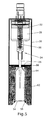
- the head element (Fig. 1) has a foam nozzle 10 which with a Housing or a cap 12 movably connected in the direction of an arrow 14 or carried by the cap 12.
- the foam nozzle 10 has one Foam outlet 16, which is connected to an adapter 18.
- the Adapter 18 or the foam outlet 16 enters the foam nozzle 10 generated medical foam from.
- the adapter 18 Device according to the invention on devices or devices for Further processing or application of the foam can be connected.
- the device can be connected to a via the adapter 18 conventional syringe can be connected to the medical foam fill into a syringe barrel.
- the foam can then injected into a vein, for example.
- the foam nozzle 10 also has a mesh or sieve holder 20. This serves to hold preferably several screens or nets with possibly different mesh sizes or porosity. To generate the medical foam flows through the fluid to be foamed and a gas the sieves or nets.
- the fluid to be foamed is removed from a liquid container 22 (FIG. 2) taken.
- the container 22 is under pressure, for example, so that by opening a valve 24 liquid through a riser 26 into a for example cylindrical container 28 arrives.
- the opening of the Valve 24 by pressing on the foam nozzle or the spray head 10.
- the cylindrical container 28 is the liquid with the help of a Spring 30 cooperating piston 32 in the direction of the net holder 20th pressed.
- a gas supply device 34 in which it is an annular slot surrounding the foam nozzle 10, Air into the foam nozzle 10.
- the suctioned air is also by the in the net holder 20 arranged screens or nets. By the A swirling of liquid and air takes place in the area of the net holder 20 Foam generation.
- a filter device 36 For filtering the air sucked in through the gap 34 is inside the gap a filter device 36 is arranged, which is shown in the Embodiment is an annular filter that increases the sterility of the intake air.
- the liquid container 22 is held by a holding body 38.
- the Holding body 38 which is essentially cylindrical, for example, also serves to hold the head element, the cap 12 of the Head element is connected to the holding part 38 such that a tight Connection is realized.
- On the opposite side of the head element the liquid container 22 is held in a cylindrical extension 40.
- the cylindrical projection 40 has an annular one or more individual ones Locking elements 42 and can also be slotted in the longitudinal direction. The or the locking elements engage behind a neck-like extension 44 of the Liquid container 22.
- the cylindrical projection 44 By an appropriate design of the cylindrical projection 44 with small tolerances or by provision a seal 45, the container 22 is sealed with the holding element 44 connected.
- a closure 46 intended.
- the closure 46 is, for example, a Plastic element or a thin metal foil. Through the closure 46 that is Riser pipe 26 out. Possibly. pierces a correspondingly pointed one End 48 of the riser pipe to the closure 46 when the container 22 is fixed the bracket 38.
- the second preferred embodiment differs from that in Fig. 2 shown first preferred embodiment only by the Type of receptacle of the container 22.
- a sheath 50 is provided.
- the casing 50 is preferably cylindrical and has the same diameter as that also preferably cylindrical Bracket 38 on.
- Inside the jacket 50 is an elastic one Lining 52 is provided.
- the elastic lining 52 encloses the Container 22 and 54 has locking elements 56 in the region of a container bottom which partially engage behind the bottom 54, so that the lining 52 the Container 22 tightly encloses.
- a seal 45 (FIG. 2) can be used in the case of FIG. 3
- the cap 12 additional adapter 56, through which additional gases are introduced into the cap can be.
- the Adapters 56 may include a check valve 58 and / or a filter 60 exhibit.
- a third embodiment of the device according to the invention corresponds essentially to the second shown in FIG. 3 Embodiment, the foam nozzle 10 and the cap 12 not in FIG. 5 is shown.
- the liquid container 22 is, in particular, made of glass existing ampoule 62 is provided. Since the glass ampoule 62 has no neck has, corresponding to the embodiment shown in Fig. 3 by a cylindrical extension 40 can be held with locking elements 42, are the latching elements 56 which engage behind the base 54 of the ampoule, if necessary somewhat larger.
- a seal 66 is provided which the Seal 45 (Fig. 2) corresponds and penetrated by the riser 26 or is pierced.
- FIG. 6 corresponds to the bracket 38 and the area in which the medical foam is produced, which is shown in FIG. 5 embodiment shown.
- an adapter 70 on a bottom 68 of the holder 38 can, for example, via a hose line or the like Liquid containers are connected or liquid is supplied.
- a Filter 74 arranged within a cylindrical extension pointing in the direction of the valve 24 72, which forms at least a part of the riser 26, is preferably a Filter 74 arranged.
- the extension 70 also has a seal 76.
- the head element shown in FIG. 1 instead of the design of the head element shown in FIG. 1, this can also, as shown in Fig. 7, be formed.
- the inside of the Head element provided elements for generating the medical Foams also correspond to those in FIG. 1 in this embodiment elements shown.
- FIGS. 8 and 9 A further fastening option for the liquid container 22 is shown in FIGS FIGS. 8 and 9, wherein the holding of the container 22 by means of a screwable plug 82 takes place.
- the container 22 in FIGS. 8 and 9 up postponed.
- the tip end 48 of the riser 26 pierces the Seal 45 of the container 22.
- the liquid in the container 22 passes with an inserted riser pipe 26 (Fig. 9) through an opening 84 in the Riser pipe 26.
- a seal 84 is also provided for sealing.
- One embodiment of the device according to the invention has one Cylinder and an air piston so that a different liquid-air ratio from 1: 5 to 1:10.
- a variation of the ratio is due to changes in the relation of the volumes of gases and / or Foaming agents possible, which can be done by changing the lifting height and / or by changing the radius of the cylinder or parts of the cylinder along with a change in the radius of the air piston and / or the Liquid piston can take place.
- An execution of the riser pipe can be designed so that a certain Amount of foaming agent can be removed.
- the length of the Adapted intake manifold is the length of the Adapted intake manifold.
- the manufacture of the cladding, the foam core, the filters, the Adapters, the seals and other parts are preferably made for medical items suitable materials.
- the foam device and the other parts are preferably sterilizable and can in particular also be packed sterile.
- the device according to the invention is particularly suitable for use in medical, veterinary-medical, cell-biological, immunological Field as well as for the production of a foam from drugs or other Medical devices applicable. It is also possible to use the device according to the invention foam for use as a cosmetic, as food, as food supplement, as cleaning agent or as a disinfectant.
Landscapes
- Chemical & Material Sciences (AREA)
- Chemical Kinetics & Catalysis (AREA)
- Dispersion Chemistry (AREA)
- Materials For Medical Uses (AREA)
- Containers And Packaging Bodies Having A Special Means To Remove Contents (AREA)
- Food-Manufacturing Devices (AREA)
- Medical Preparation Storing Or Oral Administration Devices (AREA)
Abstract
Description
- Fig. 1
- ein Kopfelement einer ersten Ausführungsform der erfindungsgemäßen Vorrichtung, dass eine erste Ausführungsform einer Schaumdüse aufweist,
- Fig. 2
- eine erste bevorzugte Ausführungsform der erfindungsgemäßen Vorrichtung mit dem in Fig. 1 dargestellten Kopfelement,
- Fig. 3
- eine zweite bevorzugte Ausführungsform der erfindungsgemäßen Vorrichtung mit dem in Fig. 1 dargestellten Kopfelement,
- Fig. 4
- eine bevorzugte Weiterbildung des in Fig. 1 dargestellten Kopfelements,
- Fig. 5
- eine dritte bevorzugte Ausführungsform der erfindungsgemäßen Vorrichtung mit dem in Fig. 4 dargestellten Kopfelement,
- Fig. 6
- eine vierte bevorzugte Ausführungsform der erfindungsgemäßen Vorrichtung mit dem in Fig. 4 dargestellten Kopfelement,
- Fig. 7
- eine dritte bevorzugte Ausführungsform eines Kopfelements und
- Fign. 8-9
- bevorzugte Ausführungsformen zur Aufnahme von Flüssigkeitsbehältern in der erfindungsgemäßen Vorrichtung.
Claims (11)
- Vorrichtung zur Erzeugung von medizinischem, insbesondere sterilem, Schaum aus einer Flüssigkeit, insbesondere einem Sklerosierungsmittel und einem Gas, insbesondere Luft, mit
einer Schaumdüse (10),
einer mit der Schaumdüse (10) verbundenen Gas-Zuführeinrichtung (34) und
einer mit der Schaumdüse verbundenen Flüssigkeits-Zuführeinrichtung (26),
wobei in der Gas-Zuführeinrichtung (34) eine Filtereinrichtung (36) angeordnet ist. - Vorrichtung nach Anspruch 1, dadurch gekennzeichnet, dass die Schaumdüse (10) mit einem Gehäuse (12) verbunden ist, wobei das Gehäuse eine die Schaumdüse (10) tragende Kappe (12) aufweist.
- Vorrichtung nach Anspruch 1 oder 2, dadurch gekennzeichnet, dass die Gas-Zuführeinrichtung (34) in dem Gehäuse (12) und/oder der Kappe angeordnet ist.
- Vorrichtung nach einem der Ansprüche 1 - 3, dadurch gekennzeichnet, dass die Gas-Zuführeinrichtung (34) die Schaumdüse vorzugsweise ringförmig umgibt.
- Vorrichtung nach Anspruch 4, dadurch gekennzeichnet, dass die Filtereinrichtung (36) ringförmig ausgebildet ist.
- Vorrichtung nach einem der Ansprüche 2-6, dadurch gekennzeichnet, dass das Gehäuse einen Flüssigkeitsbehälter (22), insbesondere zur Aufnahme des Sklerosierungsmittels aufweist bzw. mit diesem verbunden ist.
- Vorrichtung nach Anspruch 6, dadurch gekennzeichnet, dass der Flüssigkeitsbehälter (22) aus dem Gehäuse (38) auswechselbar ist.
- Vorrichtung nach Anspruch 6 oder 7, dadurch gekennzeichnet, dass das Gehäuse (38) ein oder mehrere Rastelemente (42,56) aufweist, durch die der Flüssigkeitsbehälter (22) mit dem Gehäuse (38) lösbar verbunden ist.
- Vorrichtung nach einem der Ansprüche 6-8, dadurch gekennzeichnet, dass das Gehäuse (38) einen oder mehrere Adapter zum Aus- und/ oder Einleiten von Gasen aufweist, wobei vorzugsweise mit dem Adapter ein Rückschlagventil verbunden ist.
- Vorrichtung nach einem der Ansprüche 1-9, dadurch gekennzeichnet, dass die Schaumdüse (10) einen Netzhalter (20) aufweist, der vorzugsweise mehrere Siebe aufweist.
- Vorrichtung nach einem der Ansprüche 1-10, dadurch gekennzeichnet, dass die Schaumdüse (10) ein Steigrohr (26) zum Zuführen von Flüssigkeiten aufweist, wobei das Steigrohr (26) vorzugsweise zum Öffnen eines Verschlusses des Flüssigkeitsbehälters (22) geeignet ist.
Applications Claiming Priority (2)
| Application Number | Priority Date | Filing Date | Title |
|---|---|---|---|
| DE20201168U | 2002-01-26 | ||
| DE20201168U DE20201168U1 (de) | 2002-01-26 | 2002-01-26 | Gerät zur Herstellung eines insbesondere sterilen Schaums |
Publications (3)
| Publication Number | Publication Date |
|---|---|
| EP1331031A2 true EP1331031A2 (de) | 2003-07-30 |
| EP1331031A3 EP1331031A3 (de) | 2004-04-28 |
| EP1331031B1 EP1331031B1 (de) | 2008-07-02 |
Family
ID=7966999
Family Applications (1)
| Application Number | Title | Priority Date | Filing Date |
|---|---|---|---|
| EP03001079A Revoked EP1331031B1 (de) | 2002-01-26 | 2003-01-18 | Vorrichtung zur Erzeugung vom medizinischem Schaum |
Country Status (6)
| Country | Link |
|---|---|
| EP (1) | EP1331031B1 (de) |
| AT (1) | ATE399590T1 (de) |
| DE (2) | DE20201168U1 (de) |
| DK (1) | DK1331031T3 (de) |
| ES (1) | ES2309242T3 (de) |
| PT (1) | PT1331031E (de) |
Cited By (4)
| Publication number | Priority date | Publication date | Assignee | Title |
|---|---|---|---|---|
| WO2006120461A1 (en) * | 2005-05-13 | 2006-11-16 | Btg International Limited | Preparation of therapeutic foam |
| US10364699B2 (en) | 2013-10-02 | 2019-07-30 | Aerocore Technologies Llc | Cleaning method for jet engine |
| EP3666259A1 (de) | 2018-12-13 | 2020-06-17 | Valeopharm GmbH | Verschäumbare wässrige zubereitungen auf biopolymerbasis mit einsatzfelxibler gas-speicherzellen-verteilung |
| US11643946B2 (en) | 2013-10-02 | 2023-05-09 | Aerocore Technologies Llc | Cleaning method for jet engine |
Families Citing this family (1)
| Publication number | Priority date | Publication date | Assignee | Title |
|---|---|---|---|---|
| CN113600042B (zh) * | 2021-09-10 | 2024-11-26 | 章天予 | 一种快速采集清洁空气的泡沫硬化剂制备装置 |
Family Cites Families (11)
| Publication number | Priority date | Publication date | Assignee | Title |
|---|---|---|---|---|
| DE626684C (de) * | 1936-02-29 | Mueller Ernst Kg | Behaelter zum Umwandeln von Fluessigkeiten in Schaummassen mittels Pressluft, insbesondere zum Herstellen von Schlagsahne | |
| US3744775A (en) * | 1972-02-02 | 1973-07-10 | Bischoff Chemical Corp | Mixing of molten plastic and gas |
| DE2659835A1 (de) * | 1976-09-24 | 1978-03-30 | Fink Chemie | Vorrichtung zum aufschaeumen von fluessigkeiten |
| JPS5760859Y2 (de) * | 1976-12-07 | 1982-12-25 | ||
| CA1192877A (en) * | 1981-12-14 | 1985-09-03 | Wright, Hershel E. | Foam dispensing device |
| DE3726612C1 (en) * | 1987-08-11 | 1988-11-03 | Lingen Maschb | Apparatus for forming foam |
| US5222633A (en) * | 1991-09-20 | 1993-06-29 | Jack W. Kaufman | Foam dispensing device |
| DE4231940A1 (de) * | 1992-09-24 | 1994-03-31 | Inter Airspray Sweden Ab Trell | Schaumsprühvorrichtung |
| US5275763A (en) * | 1992-10-26 | 1994-01-04 | Toshiharu Fukai | Nozzle for generating bubbles |
| DE9317348U1 (de) * | 1993-11-12 | 1994-01-05 | Wella Ag, 64295 Darmstadt | Vorrichtung zum dosierten Verschäumen einer Flüssigkeit |
| GB9912356D0 (en) * | 1999-05-26 | 1999-07-28 | Btg Int Ltd | Generation of microfoam |
-
2002
- 2002-01-26 DE DE20201168U patent/DE20201168U1/de not_active Expired - Lifetime
-
2003
- 2003-01-18 EP EP03001079A patent/EP1331031B1/de not_active Revoked
- 2003-01-18 DK DK03001079T patent/DK1331031T3/da active
- 2003-01-18 DE DE50310050T patent/DE50310050D1/de not_active Expired - Lifetime
- 2003-01-18 AT AT03001079T patent/ATE399590T1/de not_active IP Right Cessation
- 2003-01-18 PT PT03001079T patent/PT1331031E/pt unknown
- 2003-01-18 ES ES03001079T patent/ES2309242T3/es not_active Expired - Lifetime
Cited By (7)
| Publication number | Priority date | Publication date | Assignee | Title |
|---|---|---|---|---|
| WO2006120461A1 (en) * | 2005-05-13 | 2006-11-16 | Btg International Limited | Preparation of therapeutic foam |
| AU2006245500B2 (en) * | 2005-05-13 | 2012-08-23 | Btg International Limited | Preparation of therapeutic foam |
| US11292640B2 (en) | 2005-05-13 | 2022-04-05 | Btg International Limited | Preparation of therapeutic foam |
| US10364699B2 (en) | 2013-10-02 | 2019-07-30 | Aerocore Technologies Llc | Cleaning method for jet engine |
| US11643946B2 (en) | 2013-10-02 | 2023-05-09 | Aerocore Technologies Llc | Cleaning method for jet engine |
| EP3666259A1 (de) | 2018-12-13 | 2020-06-17 | Valeopharm GmbH | Verschäumbare wässrige zubereitungen auf biopolymerbasis mit einsatzfelxibler gas-speicherzellen-verteilung |
| DE102018009781A1 (de) | 2018-12-13 | 2020-06-18 | Valeopharm GmbH | Verschäumbare wässrige Zubereitungen auf natürlicher Biopolymerbasis mit einsatzflexibler Gas(- vor allem Sauerstoffgas)-Speicherzellen-Verteilung |
Also Published As
| Publication number | Publication date |
|---|---|
| PT1331031E (pt) | 2008-10-06 |
| DE50310050D1 (de) | 2008-08-14 |
| DK1331031T3 (da) | 2008-10-27 |
| EP1331031B1 (de) | 2008-07-02 |
| EP1331031A3 (de) | 2004-04-28 |
| DE20201168U1 (de) | 2003-06-05 |
| ES2309242T3 (es) | 2008-12-16 |
| ATE399590T1 (de) | 2008-07-15 |
Similar Documents
| Publication | Publication Date | Title |
|---|---|---|
| EP1572336B2 (de) | Vorrichtung zur erzeugung von medizinischem schaum | |
| DE60127290T2 (de) | Erzeugung eines therapeutischen mikroschaums | |
| DE102004048749B4 (de) | Vorrichtung zur Erzeugung eines medizinischen Schaums | |
| DE69332351T2 (de) | Kanüle zum gebrauch in abgabesystemen für medikamente | |
| DE69820916T2 (de) | Auftragevorrichtung eines Klebers auf Fibrinbasis | |
| DE69125812T2 (de) | Hülle für kanüle | |
| DE69838457T2 (de) | Aus zwei elementen bestehende abgabevorrichtung | |
| DE69839128T2 (de) | Spenderanordnung | |
| EP2300081B1 (de) | Ampulle mit ampullenhalterung | |
| DE69413378T2 (de) | ABGABESYSTEM FüR MEDIKAMENTE | |
| DE69827434T2 (de) | Verfahren zum Befüllen von Spritzen | |
| DE3881477T2 (de) | Misch- und Ausgabefläschchen mit zwei Kammern. | |
| DE69323729T2 (de) | Adaptor fuer eine medikamentabgabevorrichtung | |
| DE60209389T2 (de) | Lagerungs- und Abgabevorrichtung für biologisches Verschlussmittel | |
| DE69420965T2 (de) | Gerät zur kontrollierten abgabe von flüssigkeiten | |
| DE29580137U1 (de) | Zweiteilige Vorrichtung für die Verabreichung von Arzneimitteln | |
| DE2504048A1 (de) | Infusionsgeraet | |
| DE69928012T2 (de) | Injektionsvorrichtung | |
| WO2005018830A2 (de) | Vorrichtung und verfahren zum aufbewahren, mischen und austragen von komponenten | |
| DE69924402T2 (de) | Garät und methode zum befüllen einer ampulle eines nadellosen injektors | |
| WO1996008227A1 (de) | Mischeinrichtung für mittels einer spritze zu verabreichende mittel | |
| EP2300080B1 (de) | Abmischvorrichtung für eine zweikammerampulle | |
| EP1331031B1 (de) | Vorrichtung zur Erzeugung vom medizinischem Schaum | |
| US20100087776A1 (en) | Process And Apparatus For Filling A Syringe With A Thoroughly Mixed Medical Gas Mixture | |
| EP1711115B1 (de) | Einspritzvorrichtung, insbesondere für knochenzemente |
Legal Events
| Date | Code | Title | Description |
|---|---|---|---|
| PUAI | Public reference made under article 153(3) epc to a published international application that has entered the european phase |
Free format text: ORIGINAL CODE: 0009012 |
|
| AK | Designated contracting states |
Designated state(s): AT BE BG CH CY CZ DE DK EE ES FI FR GB GR HU IE IT LI LU MC NL PT SE SI SK TR |
|
| AX | Request for extension of the european patent |
Extension state: AL LT LV MK RO |
|
| PUAL | Search report despatched |
Free format text: ORIGINAL CODE: 0009013 |
|
| AK | Designated contracting states |
Kind code of ref document: A3 Designated state(s): AT BE BG CH CY CZ DE DK EE ES FI FR GB GR HU IE IT LI LU MC NL PT SE SI SK TR |
|
| AX | Request for extension of the european patent |
Extension state: AL LT LV MK RO |
|
| RIC1 | Information provided on ipc code assigned before grant |
Ipc: 7B 01F 13/00 A Ipc: 7B 01F 3/04 B Ipc: 7B 01F 3/20 B Ipc: 7B 01F 5/04 B |
|
| 17P | Request for examination filed |
Effective date: 20040909 |
|
| AKX | Designation fees paid |
Designated state(s): AT BE BG CH CY CZ DE DK EE ES FI FR GB GR HU IE IT LI LU MC NL PT SE SI SK TR |
|
| AXX | Extension fees paid |
Extension state: LT Payment date: 20040909 Extension state: RO Payment date: 20040909 Extension state: LV Payment date: 20040909 |
|
| 17Q | First examination report despatched |
Effective date: 20061115 |
|
| GRAP | Despatch of communication of intention to grant a patent |
Free format text: ORIGINAL CODE: EPIDOSNIGR1 |
|
| GRAS | Grant fee paid |
Free format text: ORIGINAL CODE: EPIDOSNIGR3 |
|
| GRAA | (expected) grant |
Free format text: ORIGINAL CODE: 0009210 |
|
| AK | Designated contracting states |
Kind code of ref document: B1 Designated state(s): AT BE BG CH CY CZ DE DK EE ES FI FR GB GR HU IE IT LI LU MC NL PT SE SI SK TR |
|
| AX | Request for extension of the european patent |
Extension state: LT LV RO |
|
| REG | Reference to a national code |
Ref country code: GB Ref legal event code: FG4D Free format text: NOT ENGLISH |
|
| REG | Reference to a national code |
Ref country code: CH Ref legal event code: EP Ref country code: CH Ref legal event code: NV Representative=s name: ISLER & PEDRAZZINI AG |
|
| REF | Corresponds to: |
Ref document number: 50310050 Country of ref document: DE Date of ref document: 20080814 Kind code of ref document: P |
|
| REG | Reference to a national code |
Ref country code: IE Ref legal event code: FG4D Free format text: LANGUAGE OF EP DOCUMENT: GERMAN |
|
| REG | Reference to a national code |
Ref country code: SE Ref legal event code: TRGR |
|
| REG | Reference to a national code |
Ref country code: PT Ref legal event code: SC4A Free format text: AVAILABILITY OF NATIONAL TRANSLATION Effective date: 20080924 |
|
| PG25 | Lapsed in a contracting state [announced via postgrant information from national office to epo] |
Ref country code: SI Free format text: LAPSE BECAUSE OF FAILURE TO SUBMIT A TRANSLATION OF THE DESCRIPTION OR TO PAY THE FEE WITHIN THE PRESCRIBED TIME-LIMIT Effective date: 20080702 |
|
| REG | Reference to a national code |
Ref country code: ES Ref legal event code: FG2A Ref document number: 2309242 Country of ref document: ES Kind code of ref document: T3 |
|
| REG | Reference to a national code |
Ref country code: IE Ref legal event code: FD4D |
|
| PG25 | Lapsed in a contracting state [announced via postgrant information from national office to epo] |
Ref country code: FI Free format text: LAPSE BECAUSE OF FAILURE TO SUBMIT A TRANSLATION OF THE DESCRIPTION OR TO PAY THE FEE WITHIN THE PRESCRIBED TIME-LIMIT Effective date: 20080702 Ref country code: BG Free format text: LAPSE BECAUSE OF FAILURE TO SUBMIT A TRANSLATION OF THE DESCRIPTION OR TO PAY THE FEE WITHIN THE PRESCRIBED TIME-LIMIT Effective date: 20081002 |
|
| REG | Reference to a national code |
Ref country code: HU Ref legal event code: AG4A Ref document number: E004373 Country of ref document: HU |
|
| PLBI | Opposition filed |
Free format text: ORIGINAL CODE: 0009260 |
|
| PG25 | Lapsed in a contracting state [announced via postgrant information from national office to epo] |
Ref country code: IE Free format text: LAPSE BECAUSE OF FAILURE TO SUBMIT A TRANSLATION OF THE DESCRIPTION OR TO PAY THE FEE WITHIN THE PRESCRIBED TIME-LIMIT Effective date: 20080702 Ref country code: EE Free format text: LAPSE BECAUSE OF FAILURE TO SUBMIT A TRANSLATION OF THE DESCRIPTION OR TO PAY THE FEE WITHIN THE PRESCRIBED TIME-LIMIT Effective date: 20080702 |
|
| PLAX | Notice of opposition and request to file observation + time limit sent |
Free format text: ORIGINAL CODE: EPIDOSNOBS2 |
|
| 26 | Opposition filed |
Opponent name: BTG INTERNATIONAL LIMITED Effective date: 20090402 |
|
| NLR1 | Nl: opposition has been filed with the epo |
Opponent name: BTG INTERNATIONAL LIMITED |
|
| PG25 | Lapsed in a contracting state [announced via postgrant information from national office to epo] |
Ref country code: MC Free format text: LAPSE BECAUSE OF NON-PAYMENT OF DUE FEES Effective date: 20090131 |
|
| PLBB | Reply of patent proprietor to notice(s) of opposition received |
Free format text: ORIGINAL CODE: EPIDOSNOBS3 |
|
| PGFP | Annual fee paid to national office [announced via postgrant information from national office to epo] |
Ref country code: SE Payment date: 20091222 Year of fee payment: 8 |
|
| PGFP | Annual fee paid to national office [announced via postgrant information from national office to epo] |
Ref country code: CH Payment date: 20100125 Year of fee payment: 8 Ref country code: CZ Payment date: 20100105 Year of fee payment: 8 Ref country code: DK Payment date: 20100125 Year of fee payment: 8 Ref country code: HU Payment date: 20100111 Year of fee payment: 8 Ref country code: PT Payment date: 20100114 Year of fee payment: 8 |
|
| PGFP | Annual fee paid to national office [announced via postgrant information from national office to epo] |
Ref country code: SK Payment date: 20100112 Year of fee payment: 8 |
|
| PGFP | Annual fee paid to national office [announced via postgrant information from national office to epo] |
Ref country code: AT Payment date: 20100120 Year of fee payment: 8 Ref country code: BE Payment date: 20100125 Year of fee payment: 8 |
|
| PGFP | Annual fee paid to national office [announced via postgrant information from national office to epo] |
Ref country code: NL Payment date: 20100121 Year of fee payment: 8 |
|
| PG25 | Lapsed in a contracting state [announced via postgrant information from national office to epo] |
Ref country code: GR Free format text: LAPSE BECAUSE OF FAILURE TO SUBMIT A TRANSLATION OF THE DESCRIPTION OR TO PAY THE FEE WITHIN THE PRESCRIBED TIME-LIMIT Effective date: 20081003 |
|
| PG25 | Lapsed in a contracting state [announced via postgrant information from national office to epo] |
Ref country code: LU Free format text: LAPSE BECAUSE OF NON-PAYMENT OF DUE FEES Effective date: 20090118 |
|
| PGFP | Annual fee paid to national office [announced via postgrant information from national office to epo] |
Ref country code: TR Payment date: 20110112 Year of fee payment: 9 |
|
| REG | Reference to a national code |
Ref country code: PT Ref legal event code: MM4A Free format text: LAPSE DUE TO NON-PAYMENT OF FEES Effective date: 20110718 |
|
| PGFP | Annual fee paid to national office [announced via postgrant information from national office to epo] |
Ref country code: GB Payment date: 20110121 Year of fee payment: 9 |
|
| BERE | Be: lapsed |
Owner name: CHEMISCHE FABRIK KREUSSLER & CO. G.M.B.H. Effective date: 20110131 |
|
| REG | Reference to a national code |
Ref country code: NL Ref legal event code: V1 Effective date: 20110801 |
|
| REG | Reference to a national code |
Ref country code: DK Ref legal event code: EBP |
|
| REG | Reference to a national code |
Ref country code: CH Ref legal event code: PL |
|
| REG | Reference to a national code |
Ref country code: SE Ref legal event code: EUG |
|
| PG25 | Lapsed in a contracting state [announced via postgrant information from national office to epo] |
Ref country code: CY Free format text: LAPSE BECAUSE OF FAILURE TO SUBMIT A TRANSLATION OF THE DESCRIPTION OR TO PAY THE FEE WITHIN THE PRESCRIBED TIME-LIMIT Effective date: 20080702 |
|
| REG | Reference to a national code |
Ref country code: SK Ref legal event code: MM4A Ref document number: E 4073 Country of ref document: SK Effective date: 20110118 |
|
| PG25 | Lapsed in a contracting state [announced via postgrant information from national office to epo] |
Ref country code: CH Free format text: LAPSE BECAUSE OF NON-PAYMENT OF DUE FEES Effective date: 20110131 Ref country code: LI Free format text: LAPSE BECAUSE OF NON-PAYMENT OF DUE FEES Effective date: 20110131 Ref country code: PT Free format text: LAPSE BECAUSE OF NON-PAYMENT OF DUE FEES Effective date: 20110718 |
|
| PG25 | Lapsed in a contracting state [announced via postgrant information from national office to epo] |
Ref country code: BE Free format text: LAPSE BECAUSE OF NON-PAYMENT OF DUE FEES Effective date: 20110131 Ref country code: AT Free format text: LAPSE BECAUSE OF NON-PAYMENT OF DUE FEES Effective date: 20110118 Ref country code: SK Free format text: LAPSE BECAUSE OF NON-PAYMENT OF DUE FEES Effective date: 20110118 Ref country code: CZ Free format text: LAPSE BECAUSE OF NON-PAYMENT OF DUE FEES Effective date: 20110118 Ref country code: HU Free format text: LAPSE BECAUSE OF NON-PAYMENT OF DUE FEES Effective date: 20110119 |
|
| PG25 | Lapsed in a contracting state [announced via postgrant information from national office to epo] |
Ref country code: NL Free format text: LAPSE BECAUSE OF NON-PAYMENT OF DUE FEES Effective date: 20110801 |
|
| PGFP | Annual fee paid to national office [announced via postgrant information from national office to epo] |
Ref country code: IT Payment date: 20120125 Year of fee payment: 10 |
|
| APBM | Appeal reference recorded |
Free format text: ORIGINAL CODE: EPIDOSNREFNO |
|
| APBP | Date of receipt of notice of appeal recorded |
Free format text: ORIGINAL CODE: EPIDOSNNOA2O |
|
| APAH | Appeal reference modified |
Free format text: ORIGINAL CODE: EPIDOSCREFNO |
|
| GBPC | Gb: european patent ceased through non-payment of renewal fee |
Effective date: 20120118 |
|
| PG25 | Lapsed in a contracting state [announced via postgrant information from national office to epo] |
Ref country code: GB Free format text: LAPSE BECAUSE OF NON-PAYMENT OF DUE FEES Effective date: 20120118 |
|
| PLAB | Opposition data, opponent's data or that of the opponent's representative modified |
Free format text: ORIGINAL CODE: 0009299OPPO |
|
| R26 | Opposition filed (corrected) |
Opponent name: BTG INTERNATIONAL LIMITED Effective date: 20090402 |
|
| PG25 | Lapsed in a contracting state [announced via postgrant information from national office to epo] |
Ref country code: SE Free format text: LAPSE BECAUSE OF NON-PAYMENT OF DUE FEES Effective date: 20110119 |
|
| PGFP | Annual fee paid to national office [announced via postgrant information from national office to epo] |
Ref country code: ES Payment date: 20130122 Year of fee payment: 11 |
|
| PG25 | Lapsed in a contracting state [announced via postgrant information from national office to epo] |
Ref country code: IT Free format text: LAPSE BECAUSE OF NON-PAYMENT OF DUE FEES Effective date: 20130118 |
|
| PG25 | Lapsed in a contracting state [announced via postgrant information from national office to epo] |
Ref country code: TR Free format text: LAPSE BECAUSE OF NON-PAYMENT OF DUE FEES Effective date: 20120118 |
|
| PGFP | Annual fee paid to national office [announced via postgrant information from national office to epo] |
Ref country code: FR Payment date: 20140124 Year of fee payment: 12 |
|
| PLAB | Opposition data, opponent's data or that of the opponent's representative modified |
Free format text: ORIGINAL CODE: 0009299OPPO |
|
| R26 | Opposition filed (corrected) |
Opponent name: BTG INTERNATIONAL LIMITED Effective date: 20090402 |
|
| REG | Reference to a national code |
Ref country code: ES Ref legal event code: FD2A Effective date: 20150730 |
|
| PG25 | Lapsed in a contracting state [announced via postgrant information from national office to epo] |
Ref country code: ES Free format text: LAPSE BECAUSE OF NON-PAYMENT OF DUE FEES Effective date: 20140119 |
|
| REG | Reference to a national code |
Ref country code: FR Ref legal event code: ST Effective date: 20150930 |
|
| PG25 | Lapsed in a contracting state [announced via postgrant information from national office to epo] |
Ref country code: FR Free format text: LAPSE BECAUSE OF NON-PAYMENT OF DUE FEES Effective date: 20150202 |
|
| PLAB | Opposition data, opponent's data or that of the opponent's representative modified |
Free format text: ORIGINAL CODE: 0009299OPPO |
|
| R26 | Opposition filed (corrected) |
Opponent name: BTG INTERNATIONAL LIMITED Effective date: 20090402 |
|
| APBU | Appeal procedure closed |
Free format text: ORIGINAL CODE: EPIDOSNNOA9O |
|
| PLAY | Examination report in opposition despatched + time limit |
Free format text: ORIGINAL CODE: EPIDOSNORE2 |
|
| PLBC | Reply to examination report in opposition received |
Free format text: ORIGINAL CODE: EPIDOSNORE3 |
|
| PLAY | Examination report in opposition despatched + time limit |
Free format text: ORIGINAL CODE: EPIDOSNORE2 |
|
| PLAB | Opposition data, opponent's data or that of the opponent's representative modified |
Free format text: ORIGINAL CODE: 0009299OPPO |
|
| R26 | Opposition filed (corrected) |
Opponent name: BTG INTERNATIONAL LIMITED Effective date: 20090402 |
|
| REG | Reference to a national code |
Ref country code: ES Ref legal event code: FD2A Effective date: 20181205 |
|
| PGFP | Annual fee paid to national office [announced via postgrant information from national office to epo] |
Ref country code: DE Payment date: 20210201 Year of fee payment: 19 |
|
| REG | Reference to a national code |
Ref country code: DE Ref legal event code: R079 Ref document number: 50310050 Country of ref document: DE Free format text: PREVIOUS MAIN CLASS: B01F0013000000 Ipc: B01F0033000000 |
|
| REG | Reference to a national code |
Ref country code: DE Ref legal event code: R119 Ref document number: 50310050 Country of ref document: DE |
|
| RDAF | Communication despatched that patent is revoked |
Free format text: ORIGINAL CODE: EPIDOSNREV1 |
|
| STAA | Information on the status of an ep patent application or granted ep patent |
Free format text: STATUS: THE PATENT HAS BEEN GRANTED |
|
| REG | Reference to a national code |
Ref country code: DE Ref legal event code: R103 Ref document number: 50310050 Country of ref document: DE Ref country code: DE Ref legal event code: R064 Ref document number: 50310050 Country of ref document: DE |
|
| PG25 | Lapsed in a contracting state [announced via postgrant information from national office to epo] |
Ref country code: DE Free format text: LAPSE BECAUSE OF NON-PAYMENT OF DUE FEES Effective date: 20220802 |
|
| RDAG | Patent revoked |
Free format text: ORIGINAL CODE: 0009271 |
|
| STAA | Information on the status of an ep patent application or granted ep patent |
Free format text: STATUS: PATENT REVOKED |
|
| PUAJ | Public notification under rule 129 epc |
Free format text: ORIGINAL CODE: 0009425 |
|
| 27W | Patent revoked |
Effective date: 20221001 |
|
| REG | Reference to a national code |
Ref country code: SK Ref legal event code: MC4A Ref document number: E 4073 Country of ref document: SK Effective date: 20221001 |
|
| 32PN | Public notification |
Free format text: ENTSCHEIDUNG UEBER DIE ZURUECKWEISUNG DER EUROPAEISCHEN PATENTANMELDUNG (EPA FORM 2333 VOM 21.09.2022) |
|
| REG | Reference to a national code |
Ref country code: AT Ref legal event code: MA03 Ref document number: 399590 Country of ref document: AT Kind code of ref document: T Effective date: 20221001 |