EP1331018A1 - Haltenadel mit flügel - Google Patents
Haltenadel mit flügel Download PDFInfo
- Publication number
- EP1331018A1 EP1331018A1 EP20020751715 EP02751715A EP1331018A1 EP 1331018 A1 EP1331018 A1 EP 1331018A1 EP 20020751715 EP20020751715 EP 20020751715 EP 02751715 A EP02751715 A EP 02751715A EP 1331018 A1 EP1331018 A1 EP 1331018A1
- Authority
- EP
- European Patent Office
- Prior art keywords
- tub
- shaped member
- hollow needle
- rack
- rear end
- Prior art date
- Legal status (The legal status is an assumption and is not a legal conclusion. Google has not performed a legal analysis and makes no representation as to the accuracy of the status listed.)
- Granted
Links
Images


Classifications
-
- A—HUMAN NECESSITIES
- A61—MEDICAL OR VETERINARY SCIENCE; HYGIENE
- A61M—DEVICES FOR INTRODUCING MEDIA INTO, OR ONTO, THE BODY; DEVICES FOR TRANSDUCING BODY MEDIA OR FOR TAKING MEDIA FROM THE BODY; DEVICES FOR PRODUCING OR ENDING SLEEP OR STUPOR
- A61M25/00—Catheters; Hollow probes
- A61M25/01—Introducing, guiding, advancing, emplacing or holding catheters
- A61M25/06—Body-piercing guide needles or the like
- A61M25/0612—Devices for protecting the needle; Devices to help insertion of the needle, e.g. wings or holders
- A61M25/0637—Butterfly or winged devices, e.g. for facilitating handling or for attachment to the skin
-
- A—HUMAN NECESSITIES
- A61—MEDICAL OR VETERINARY SCIENCE; HYGIENE
- A61M—DEVICES FOR INTRODUCING MEDIA INTO, OR ONTO, THE BODY; DEVICES FOR TRANSDUCING BODY MEDIA OR FOR TAKING MEDIA FROM THE BODY; DEVICES FOR PRODUCING OR ENDING SLEEP OR STUPOR
- A61M25/00—Catheters; Hollow probes
- A61M25/01—Introducing, guiding, advancing, emplacing or holding catheters
- A61M25/06—Body-piercing guide needles or the like
- A61M25/0612—Devices for protecting the needle; Devices to help insertion of the needle, e.g. wings or holders
- A61M25/0631—Devices for protecting the needle; Devices to help insertion of the needle, e.g. wings or holders having means for fully covering the needle after its withdrawal, e.g. needle being withdrawn inside the handle or a cover being advanced over the needle
-
- A—HUMAN NECESSITIES
- A61—MEDICAL OR VETERINARY SCIENCE; HYGIENE
- A61M—DEVICES FOR INTRODUCING MEDIA INTO, OR ONTO, THE BODY; DEVICES FOR TRANSDUCING BODY MEDIA OR FOR TAKING MEDIA FROM THE BODY; DEVICES FOR PRODUCING OR ENDING SLEEP OR STUPOR
- A61M5/00—Devices for bringing media into the body in a subcutaneous, intra-vascular or intramuscular way; Accessories therefor, e.g. filling or cleaning devices, arm-rests
- A61M5/178—Syringes
- A61M5/31—Details
- A61M5/32—Needles; Details of needles pertaining to their connection with syringe or hub; Accessories for bringing the needle into, or holding the needle on, the body; Devices for protection of needles
- A61M5/3205—Apparatus for removing or disposing of used needles or syringes, e.g. containers; Means for protection against accidental injuries from used needles
- A61M5/321—Means for protection against accidental injuries by used needles
- A61M5/3243—Means for protection against accidental injuries by used needles being axially-extensible, e.g. protective sleeves coaxially slidable on the syringe barrel
- A61M5/3245—Constructional features thereof, e.g. to improve manipulation or functioning
- A61M2005/3247—Means to impede repositioning of protection sleeve from needle covering to needle uncovering position
- A61M2005/325—Means obstructing the needle passage at distal end of a needle protection sleeve
-
- A—HUMAN NECESSITIES
- A61—MEDICAL OR VETERINARY SCIENCE; HYGIENE
- A61M—DEVICES FOR INTRODUCING MEDIA INTO, OR ONTO, THE BODY; DEVICES FOR TRANSDUCING BODY MEDIA OR FOR TAKING MEDIA FROM THE BODY; DEVICES FOR PRODUCING OR ENDING SLEEP OR STUPOR
- A61M5/00—Devices for bringing media into the body in a subcutaneous, intra-vascular or intramuscular way; Accessories therefor, e.g. filling or cleaning devices, arm-rests
- A61M5/178—Syringes
- A61M5/31—Details
- A61M5/32—Needles; Details of needles pertaining to their connection with syringe or hub; Accessories for bringing the needle into, or holding the needle on, the body; Devices for protection of needles
- A61M5/3205—Apparatus for removing or disposing of used needles or syringes, e.g. containers; Means for protection against accidental injuries from used needles
- A61M5/321—Means for protection against accidental injuries by used needles
- A61M5/3243—Means for protection against accidental injuries by used needles being axially-extensible, e.g. protective sleeves coaxially slidable on the syringe barrel
Definitions
- the present invention relates to a winged indwelling needle which is used for temporarily securing a venous path or the like.
- a winged indwelling needle As a needle used for a medical practice such as temporary securing of a venous path, a winged indwelling needle has conventionally been known, which comprises a hollow needle, a hub for holding a rear end of the hollow needle, and a pair of wing-shaped members formed integrally with the hub.
- a medical personnel such as a doctor or a nurse first removes a protector attached to the hollow needle, grips the pair of wing-shaped members in a superposed manner, and then sticks the hollow needle into a vein of a patient. Then, he fixes the hollow needle by opening the pair of wing-shaped members, and pasting them to a body surface of the patient by adhesive tape or the like.
- the winged indwelling needle is pulled out, and disposed of.
- the medical personnel or a worker engaged in disposal (abbreviated to medical personnel, hereinafter) may stick the hollow needle into a finger or the like accidentally (abbreviated to accidental sticking, hereinafter).
- an infectious disease such as HIV or acute hepatitis
- the medical personnel may be infected with the disease through the hollow needle.
- the conventional protector has a hollow cylindrical body provided with a length equal to that of the hollow needle. Accordingly, the recapping is carried out by approaching the protector and the hollow needle to each other in an extended direction of the hollow needle, and inserting the hollow needle from its tip into an opening end of the protector.
- Japanese Patent No. 3198492 discloses a winged indwelling needle, which comprises a hollow needle, a holder, into which the hollow needle is inserted, and protruded from a tip, and a pair of wing-shaped members provided in the holder.
- a hub provided at a rear end of the hollow needle is freely engaged with the holder, and the hollow needle is protruded from the tip of the holder while the hub is in the engaged state with the holder. Accordingly, the winged indwelling needle can be fixed by sticking the hollow needle protruded from the tip of the holder into a vein of a patient, and by opening the pair of wing-shaped members and pasting them to a body surface of the patient.
- the hollow needle is housed in the holder by disengaging the hub from the holder while the wing-shaped members are pasted to the patient, and retreating the hub.
- the holder becomes a protector of the hollow needle, which can prevent accidental sticking.
- the present invention was made to solve the foregoing inconvenience, and it is an object of the invention to provide an easily operable winged indwelling needle capable of surely preventing accidental sticking.
- a winged indwelling needle of the present invention comprises a hollow needle having a knife point at its tip, a hub provided at a rear end of the hollow needle, a tub-shaped member for housing the hollow needle and the hub slidingly in a longitudinal direction, a pair of wing-shaped members provided on an outer surface side of a side wall of the tub-shaped member, protrusion maintaining means for releasably maintaining a state in which the hollow needle is protruded as much as a predetermined length from a tip of the tub-shaped member, and housing maintaining means for maintaining a state in which the hollow needle is housed in the tub-shaped member, the above winged indwelling needle further comprising a rack provided in junction with the rear end of the hub, and a gear engaged with the rack and supported on an inner surface side of the side wall of the tub-shaped member, the hollow needle being driven through the rack by rotating the gear to be housed in the tub-shaped member.
- the winged indwelling needle of the present invention first, a medical personnel such as a doctor or a nurse grips the tub-shaped member, or the pair of the wing-shaped members in a superposed manner, and sticks the hollow needle into a patient. At this time, the hollow needle is maintained in the state of being protruded from the tip of the tub-shaped member by the predetermined length by the protrusion maintaining means. As a result, since the hollow needle is maintained in the state of being protruded from the tip of the tub-shaped member, and not moved forward/backward, a needle point is never moved, thereby facilitating the sticking operation.
- the hollow needle In the winged indwelling needle, after the hollow needle is stuck into the patient, the hollow needle is fixed by opening the wing-shaped members, and pasting them to a body surface of the patient by adhesive tape or the like. At this time, the protrusion maintaining means regulates retreating of the hollow needle, making it possible to prevent the hollow needle from being pulled out from the patient.
- the hollow needle When the hollow needle is pulled out from the body of the patient, first, the regulation by the protrusion maintaining means is released. Then, the tub-shaped member is held by one hand. When the gear is rotated by fingers of the hand gripping the tub-shaped member, the gear drives the hollow needle through the rack, and the hollow needle is housed in the tub-shaped member. Then, by using the housing maintaining means, the hollow needle is maintained in the state of being housed in the tub-shaped member at a position where the tip of the hollow needle is housed in the tub-shaped member. As a result, it is possible to prevent the hollow needle from being protruded again from the tip of the tub-shaped member.
- the tub-shaped member After the hollow needle is housed in the tub-shaped member, the tub-shaped member operates as a protector, thereby preventing the finger of the medical personnel from touching the hollow needle.
- the winged indwelling needle of the present invention the conventional necessity of approaching the protector and the hollow needle to each other by both hands, and inserting the hollow needle into the opening of the protector is eliminated, making it possible to surely prevent accidental sticking. Moreover, in the winged indwelling needle of the invention, since the gear is rotated by one hand to house the hollow needle in the tub-shaped member, thus facilitating an operation.
- the protrusion maintaining means comprises, for example, a first extension member provided at the rear end of the rack to be extended in a direction along the side wall, and a locking member which is provided to freely open and close the rear end of the tub-shaped member and which locks a rear end of the extension member so as to maintain a state in which the hollow needle is protruded as much as a predetermined length from the tip of the tub-shaped member when the rear end of the tub-shaped member is closed.
- the protrusion maintaining means comprises a first handle integrally attached to the gear rotatably together with the gear, and a first protruded portion provided on an inner surface side of the side wall at the rear end of the tub-shaped member to detachably lock the first handle at a position where the hollow needle is protruded as much as a predetermined length from the tip of the tub-shaped member.
- the housing maintaining means comprises, for example, a second protruded portion provided to be protruded from the tip of the rack to its side, and an engaging concave portion provided on the inner surface side of the side wall at the rear end of the tub-shaped member and engaged with the second protruded portion so as to maintain a state in which the hollow needle is housed in the tub-shaped member.
- the housing maintaining means comprises a second handle integrally attached to the gear rotatably together with the gear, and a third protruded portion provided on the inner surface side of the side wall in the tip of the tub-shaped member to detachably lock the second handle at a position where the hollow needle is housed in the tub-shaped member.
- the second handle preferably comprises, on its tip, a branch portion which is arranged in front of the knife point of the hollow needle when the second handle is engaged with the third protruded portion.
- the first and second modes of the protrusion maintaining means, and the first and second modes of the housing maintaining means can be freely combined with each other.
- the first and second handles are constructed similarly to each other.
- the rack preferably comprises a second extension member extended from the rear end to the side to lock a rear end surface of the tub-shaped member, thereby preventing the tub-shaped member from moving behind the rack.
- the second extension member the operation of sticking the hollow needle into the patient can be performed more stably by preventing the tub-shaped member from being moved behind the rack.
- FIG. 1 is an explanatory sectional view showing constitution of a winged indwelling needle according to a first embodiment of the present invention.
- FIG. 2 is a partially cutout plan view of the winged indwelling needle shown in FIG. 1.
- FIG. 3 is an explanatory sectional view showing an operation of the winged indwelling needle shown in FIG. 1.
- FIG. 4 is an explanatory partially cutout plan view showing an operation of the winged indwelling needle shown in FIG. 1.
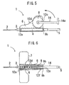
- FIG. 5 is an explanatory sectional view showing a winged indwelling needle according to a second embodiment of the present invention.
- FIG. 6 is a partially cutout plan view of the winged indwelling needle shown in FIG. 5.
- FIG. 7 is an explanatory sectional view showing an operation of the indwelling needle shown in FIG. 5.
- FIG. 8 is an explanatory partially cutout plan view showing an operation of the indwelling needle shown in FIG. 5.
- a winged indwelling needle 1 of the present invention comprises a hollow needle 2 having a knife point on its tip, and a hub 3 provided at a rear end of the hollow needle 2.
- a hollow rack 4 is provided in junction with a rear end of the hub 3.
- a tube 5 is connected to a rear end of the rack extended in a rear direction, which guides drug solution through the hub 3 and the rack 4 to the hollow needle 2.
- the hub 3 and the rack 4 are housed in a tub-shaped member 6 so as to be freely slid in a longitudinal direction therein.
- the tub-shaped member 6 is made of a synthetic resin and, an outer surface side of a side wall, a pair of wing-shape members 7 are horizontally provided integrally.
- the tube 5 may be inserted into the rack 4, and connected to the hub 3.
- the tub-shaped member 6 has two side walls extended upward on both sides of the housed rack 4. Between the side walls, a gear 8 engaged with the rack 4 is supported. An upper portion of the gear 8 is exposed from upper edges of both side walls of the tub-shaped member 6 indicated by a chain line in FIG. 1, so as to be freely rotated.
- an extension member 9a is provided to be extended upward.
- a locking member 10 L-shaped on plane is provided in junction so as to be bent freely in a position for contact with the extension member 9a in the upper side of the rack 4 on one side of the side wall.
- An engaging concave portion 11a is provided in a tip of the locking member 10 so as to be freely engaged with a protruded portion 12a protruded on an outer surface side of the other side wall of the tub-shaped member 6.
- the protruded portion 12a is formed to have a tapered rear side, and a surface of a tip perpendicular to the side wall.
- the present invention constructs a first mode of protrusion maintaining means for maintaining a state of the hollow needle 2 being protruded from the tip of the tub-shaped member 6 by a predetermined length by the extension member 9a and the locking member 10.
- an extension member 9b is provided at a rear end of the rack 4, which is extended in a side face direction. By locking the rear end surface of the tub-shaped member 6, the extension member 9b can regulate the tub-shaped member 6 to prevent its retreating with respect to the rack 4.
- a protruded portion 12a is formed to have a tapered rear side, and a tip surface perpendicular to the side wall.
- an engaging concave portion 11b is provided to have a tapered tip, and a surface perpendicular to the inner surface side of the side wall after the tapered portion.
- the rack 4 is regulated for forward/backward movement by engaging the perpendicular surface of the protruded portion 12b with the perpendicular surface of the engaging portion 11b. That is, the embodiment forms a first mode of housing maintaining means for maintaining a state of the hollow needle 2 being housed in the tub-shaped member 6 by engaging the protruded portion 12b with the engaging portion 11b.
- the medical personnel first grips the tub-shaped member 6, or the pair of wing-shaped members 7 in a superposed manner, and sticks the hollow needle 2 protruded from the tub-shaped member 6 into a patient.
- the medical personnel expands the pair of wing-shaped members 7, and retains the hollow needle 2 by pasting them to a body surface of the patient to fix the hollow needle 2.
- a venous path is temporarily secured by the hollow needle 2.
- drug administration is carried out by introducing drug solution or the like from the tube 5 through the hollow needle 2 into a vein.
- the extension member 9a provided at the rear end of the rack 4 is locked by the locking member 10.
- the extension member 9b locks the rear end surface of the tub-shaped member 6, thereby preventing the tub-shaped member 6 from being retreated with respect to the position of the hollow needle 2. Therefore, the hollow needle 2 is surely fixed by pasting the wing-shaped members 7, making it possible to perform the operation such as drug administration in a stable manner.
- the medical personnel To remove the hollow needle 2, and house it in the tub-shaped member 6, the medical personnel first operates the engaging portion 11a of the locking member 10, and moves it in a direction away from the side wall surface of the tub-shaped member 6. As a result, the engagement between the protruded portion 12a and the locking member 11a is released, the extension member 9a is not regulated by the locking member 10, and the rack 4 is freely moved to the rear side of the tub-shaped member 6.
- the medical personnel rotates the gear 8 toward the tip of the hollow needle 2 by a finger.
- the rack 4 engaged with the gear 8 is driven to be retreated, and the hollow needle 2 is retreated as shown in FIGS. 3 and 4.
- the protruded portion 12b provided on the outer surface side of the side wall of the rack 4 is engaged with the engaging portion 11b provided on the inner surface side of the side wall of the tub-shaped member 6.
- the protruded portion 12b has a tapered rear end.
- the rear end of the protruded portion 12b is guided by the tapered portion provided in the tip of the engaging portion 11b to be moved in a rear direction, and engaged with the concave portion of the engaging portion 11b after going over the tapered portion.
- the winged indwelling needle 1 can maintain the state of the hollow needle 2 being housed in the tub-shaped member 6 and, once housed in the tub-shaped member 6, the hollow needle 2 is never protruded again from the tip of the tip of the tub-shaped member 6. Thus, it is possible to prevent the medical personnel from accidentally sticking the hollow needle 2 protruded from the tip of the tub-shaped member 6.
- the tub-shaped member 6 has the cylindrical portion 13 formed on its tip, the tip of the housed hollow needle 2 is surrounded with the cylindrical portion 13.
- the tub-shaped member 6 has the cylindrical portion 13 formed on its tip, the tip of the housed hollow needle 2 is surrounded with the cylindrical portion 13.
- a winged indwelling needle 1 according to a second embodiment of the present invention is completely similar in constitution to the winged indwelling needle 1 of the first embodiment except the protrusion maintaining means and the housing maintaining means.
- similar components are denoted by similar reference numerals, and detailed description thereof will be omitted.
- the second embodiment employs a second mode, where the protrusion maintaining means includes an L-shaped handle 14 integrally attached to the gear 8, and associatively rotated therewith, and a protruded portion 12c provided at a rear end of the tub-shaped member 6 to detachably lock the L-shaped handle 14.
- the protruded portion 12c is provided to be protruded on the inner surface side of the side wall at the rear end of the tub-shaped member 6.
- the protruded portion 12c locks the L-shaped handle 14, and regulates rotation of the L-shaped handle 14 toward the tip of the tub-shaped member 6.
- the second embodiment employs a second mode, where the housing maintaining means includes the L-shaped handle 14, and a protruded portion 12d provided in the tip of the tub-shaped member 6 to detachably lock the L-shaped handle 14.
- the protruded portion 12d is provided to be protruded on the inner surface side of the side wall in the tip of the tub-shaped member 6.
- the protruded portion 12d locks the L-shaped handle 14, and regulates rotation of the L-shaped handle 14 in the rear end direction of the tub-shaped member 6.
- a protruded portion 12e is provided to be protruded from the tip of the rack 4 to the side, and a protruded portion 12f provided on the inner surface side of the side wall at the rear end of the tub-shaped member 6.
- the tub-shaped member 6 has an opening above the rack 4 on a full length, and the side wall of the tub-shaped member 6 substantially covers the gear 8 excluding the L-shaped handle 14.
- the L-shaped handle 14 includes a branch portion formed on its tip.
- the hollow needle 2 is stuck into the patient, fixed and retained. Then, drug administration is carried out through the tube 5.
- the gear 8 engaged with the rack 4 is rotated toward the tip of the hollow needle 2.
- the L-shaped handle 14 integrally attached to the gear 8 is locked by the protruded portion 12c.
- the L-shaped handle 14 locked in the protruded portion 12c regulates rotation of the gear 8 to block retreating of the hollow needle 2, making it possible to maintain the state of the hollow needle 2 being protruded from the tip of the tub-shaped member 6 by a predetermined length.
- the extension member 9b locks the rear end surface of the tub-shaped member 6.
- the medical personnel first grips the L-shaped handle 14, and rotates the hollow needle toward to a tip as indicated by an arrow in FIG. 5. Since the tub-shaped member 6 and the protruded portion 12c are made of synthetic resins, by applying a predetermined force or more to the L-shaped handle 14, the protruded portion 12c abutted on the L-shaped handle 14 is widened toward the side wall of the tub-shaped member 6. Thus, the L-shaped handle 14 can be rotated toward the tip of the hollow needle 2 after going over the protruded portion 12c.
- the protruded portion 12d abutted on the L-shaped handle 14 is widened toward the side wall of the tub-shaped member 6. Then, the L-shaped handle 14 is locked on the bottom surface of the protruded portion 12d after going over the protruded portion 12d.
- the winged indwelling needle 1 can maintain the state of the hollow needle 2 being housed in the tub-shaped member 6 and, once housed in the tub-shaped member 6, the hollow needle 2 is never protruded again from the tip of the tub-shaped member 6. Therefore, it is possible to prevent the medical personnel or the like from accidentally sticking the hollow needle 2 protruded from the tip of the tub-shaped member 6.
- the branch portion 14a is arranged in front of the knife point of the hollow needle 2 in the tub-shaped member 6.
- the opening surface above the rack 4, and the tip opening as a path for protrusion of the hollow needle 2 are covered with the L-shaped handle 14.
- the protruded portion 12e provided on the side face in the tip of the rack 4 is locked by the protruded portion 12f provided on the inner surface side of the side wall at the rear end of the tub-shaped member 6.
- means may be provided for maintaining engagement between the rack 4 and the gear 4 when the hollow needle 2 is housed in the tub-shaped member 6.
- the first mode of the protrusion maintaining means is combined with the first mode of the housing maintaining means, and the second modes thereof are combined with each other.
- the first mode of the protrusion maintaining means may be connected to the second mode of the housing maintaining means.
- the second mode of the protrusion maintaining means may be combined with the first mode of the housing maintaining means.
- the present invention can be applied to a winged indwelling needle used for temporarily securing a venous path or the like.
Landscapes
- Health & Medical Sciences (AREA)
- Life Sciences & Earth Sciences (AREA)
- Biophysics (AREA)
- Pulmonology (AREA)
- Engineering & Computer Science (AREA)
- Anesthesiology (AREA)
- Biomedical Technology (AREA)
- Heart & Thoracic Surgery (AREA)
- Hematology (AREA)
- Animal Behavior & Ethology (AREA)
- General Health & Medical Sciences (AREA)
- Public Health (AREA)
- Veterinary Medicine (AREA)
- Infusion, Injection, And Reservoir Apparatuses (AREA)
Applications Claiming Priority (3)
| Application Number | Priority Date | Filing Date | Title |
|---|---|---|---|
| JP2001287689 | 2001-09-20 | ||
| JP2001287689A JP3655857B2 (ja) | 2001-09-20 | 2001-09-20 | 翼付留置針 |
| PCT/JP2002/007591 WO2003026725A1 (fr) | 2001-09-20 | 2002-07-26 | Aiguille de retenue a ailettes |
Publications (3)
| Publication Number | Publication Date |
|---|---|
| EP1331018A1 true EP1331018A1 (de) | 2003-07-30 |
| EP1331018A4 EP1331018A4 (de) | 2004-12-15 |
| EP1331018B1 EP1331018B1 (de) | 2006-07-19 |
Family
ID=19110458
Family Applications (1)
| Application Number | Title | Priority Date | Filing Date |
|---|---|---|---|
| EP02751715A Expired - Lifetime EP1331018B1 (de) | 2001-09-20 | 2002-07-26 | Haltenadel mit flügel |
Country Status (7)
| Country | Link |
|---|---|
| US (1) | US6942642B2 (de) |
| EP (1) | EP1331018B1 (de) |
| JP (1) | JP3655857B2 (de) |
| DE (1) | DE60213194T2 (de) |
| MY (1) | MY134839A (de) |
| TW (1) | TW550102B (de) |
| WO (1) | WO2003026725A1 (de) |
Cited By (4)
| Publication number | Priority date | Publication date | Assignee | Title |
|---|---|---|---|---|
| EP1658876A1 (de) * | 2004-11-17 | 2006-05-24 | Clinico GmbH | Auszieheinrichtung zum geschützten Herausziehen einer flexiblen Punktionsnadel aus einem Katheter |
| WO2015020823A1 (en) * | 2013-08-07 | 2015-02-12 | Bristol-Myers Squibb Comapny | Injection aid for use with an injection device and method of use |
| CN107583127A (zh) * | 2017-08-31 | 2018-01-16 | 安徽信息工程学院 | 输液器 |
| RU2655272C2 (ru) * | 2014-02-24 | 2018-05-24 | Медифёст Ко., Лтд. | Безопасный катетер |
Families Citing this family (21)
| Publication number | Priority date | Publication date | Assignee | Title |
|---|---|---|---|---|
| US20070073224A1 (en) * | 2005-07-14 | 2007-03-29 | John Dries | Syringe with latching safety mechanism |
| US7909789B2 (en) | 2006-06-26 | 2011-03-22 | Sight Sciences, Inc. | Intraocular implants and methods and kits therefor |
| JP4994775B2 (ja) | 2006-10-12 | 2012-08-08 | 日本コヴィディエン株式会社 | 針先保護具 |
| US8529622B2 (en) | 2010-02-05 | 2013-09-10 | Sight Sciences, Inc. | Intraocular implants and related kits and methods |
| US8486024B2 (en) | 2011-04-27 | 2013-07-16 | Covidien Lp | Safety IV catheter assemblies |
| WO2013040154A1 (en) * | 2011-09-15 | 2013-03-21 | Helm Robert E Jr | Catheter-dressing systems with integrated flushing mechanisms |
| EP2760521B1 (de) | 2011-09-26 | 2016-01-06 | Covidien LP | Sicherheits-iv-katheter und nadelanordnung |
| WO2013048975A1 (en) | 2011-09-26 | 2013-04-04 | Covidien Lp | Safety catheter |
| US8834422B2 (en) | 2011-10-14 | 2014-09-16 | Covidien Lp | Vascular access assembly and safety device |
| US8894603B2 (en) | 2012-03-20 | 2014-11-25 | Sight Sciences, Inc. | Ocular delivery systems and methods |
| GB201321078D0 (en) * | 2013-11-29 | 2014-01-15 | Smiths Medical Int Ltd | Syringe assemblies |
| KR101551812B1 (ko) | 2014-01-14 | 2015-09-11 | 강원대학교산학협력단 | 약물주입기용 니들 삽입 장치 및 그의 구동방법 |
| US9925088B2 (en) | 2014-06-06 | 2018-03-27 | Janssen Biotech, Inc. | Sub-retinal tangential needle catheter guide and introducer |
| US10299958B2 (en) | 2015-03-31 | 2019-05-28 | Sight Sciences, Inc. | Ocular delivery systems and methods |
| DK3380150T3 (da) * | 2015-11-27 | 2020-09-07 | Sanofi Aventis Deutschland | Injektionsanordning med aksialt bevægelig kanyleholder |
| EP3332822A1 (de) | 2016-12-07 | 2018-06-13 | Sanofi-Aventis Deutschland GmbH | Einspritzvorrichtung |
| CN107854128B (zh) * | 2017-12-18 | 2020-10-09 | 浙江赛微思生物科技有限公司 | 一种便于取血的医疗检测采血器 |
| CN108567525A (zh) * | 2018-05-17 | 2018-09-25 | 马飞 | 撕囊镊 |
| US11504270B1 (en) | 2019-09-27 | 2022-11-22 | Sight Sciences, Inc. | Ocular delivery systems and methods |
| CN220938089U (zh) * | 2020-12-31 | 2024-05-14 | 杭州德晋医疗科技有限公司 | 介入器械操控辅件及介入式医疗系统 |
| CN113144324B (zh) * | 2021-04-23 | 2022-04-08 | 中国人民解放军总医院第三医学中心 | 一种滞留针固定装置 |
Citations (4)
| Publication number | Priority date | Publication date | Assignee | Title |
|---|---|---|---|---|
| GB189903258A (en) * | 1899-02-14 | 1899-03-18 | Harry Judson Williams | Improvements in Cork Extractors. |
| GB1188579A (en) * | 1966-08-05 | 1970-04-22 | Tullio Compagnolo | Corkscrew |
| US5067946A (en) * | 1990-04-10 | 1991-11-26 | Semen Zhadanov | Injury resistant needle device |
| US6228066B1 (en) * | 1999-06-28 | 2001-05-08 | Sam Zhadanov | Injury resistant needle device |
Family Cites Families (5)
| Publication number | Priority date | Publication date | Assignee | Title |
|---|---|---|---|---|
| JP3198492B2 (ja) | 1993-06-18 | 2001-08-13 | ニプロ株式会社 | 翼付留置針 |
| JP3134920B2 (ja) * | 1996-09-20 | 2001-02-13 | 株式会社ニッショー | 翼付留置針 |
| WO2000056384A1 (en) * | 1999-03-19 | 2000-09-28 | Peter Balfour Dugmore | An adjustable needle assembly |
| JP4348578B2 (ja) | 1999-04-26 | 2009-10-21 | 株式会社ジェイ・エム・エス | 翼付き注射針装置 |
| JP2001245980A (ja) | 2000-03-08 | 2001-09-11 | Mitsubishi Pencil Co Ltd | 安全留置針 |
-
2001
- 2001-09-20 JP JP2001287689A patent/JP3655857B2/ja not_active Expired - Fee Related
-
2002
- 2002-07-26 WO PCT/JP2002/007591 patent/WO2003026725A1/ja active IP Right Grant
- 2002-07-26 EP EP02751715A patent/EP1331018B1/de not_active Expired - Lifetime
- 2002-07-26 DE DE60213194T patent/DE60213194T2/de not_active Expired - Lifetime
- 2002-07-26 US US10/416,327 patent/US6942642B2/en not_active Expired - Fee Related
- 2002-09-04 TW TW091120207A patent/TW550102B/zh active
- 2002-09-18 MY MYPI20023469A patent/MY134839A/en unknown
Patent Citations (4)
| Publication number | Priority date | Publication date | Assignee | Title |
|---|---|---|---|---|
| GB189903258A (en) * | 1899-02-14 | 1899-03-18 | Harry Judson Williams | Improvements in Cork Extractors. |
| GB1188579A (en) * | 1966-08-05 | 1970-04-22 | Tullio Compagnolo | Corkscrew |
| US5067946A (en) * | 1990-04-10 | 1991-11-26 | Semen Zhadanov | Injury resistant needle device |
| US6228066B1 (en) * | 1999-06-28 | 2001-05-08 | Sam Zhadanov | Injury resistant needle device |
Non-Patent Citations (1)
| Title |
|---|
| See also references of WO03026725A1 * |
Cited By (9)
| Publication number | Priority date | Publication date | Assignee | Title |
|---|---|---|---|---|
| EP1658876A1 (de) * | 2004-11-17 | 2006-05-24 | Clinico GmbH | Auszieheinrichtung zum geschützten Herausziehen einer flexiblen Punktionsnadel aus einem Katheter |
| US7220242B2 (en) | 2004-11-17 | 2007-05-22 | Clinico Gmbh | Withdrawal device for the secure withdrawal of a flexible puncture needle from a catheter, in particular from a catheter with a flexible catheter tube |
| WO2015020823A1 (en) * | 2013-08-07 | 2015-02-12 | Bristol-Myers Squibb Comapny | Injection aid for use with an injection device and method of use |
| CN105431183A (zh) * | 2013-08-07 | 2016-03-23 | 百时美施贵宝公司 | 用于与注射装置一起使用的注射辅助装置及使用方法 |
| CN105431183B (zh) * | 2013-08-07 | 2019-07-30 | 百时美施贵宝公司 | 用于与注射装置一起使用的注射辅助装置及使用方法 |
| US10398849B2 (en) | 2013-08-07 | 2019-09-03 | Bristol-Myers Squibb Comapny | Injection aid for use with an injection device and method of use |
| RU2655272C2 (ru) * | 2014-02-24 | 2018-05-24 | Медифёст Ко., Лтд. | Безопасный катетер |
| US10286187B2 (en) | 2014-02-24 | 2019-05-14 | Medifirst Co., Ltd. | Safe catheter |
| CN107583127A (zh) * | 2017-08-31 | 2018-01-16 | 安徽信息工程学院 | 输液器 |
Also Published As
| Publication number | Publication date |
|---|---|
| EP1331018B1 (de) | 2006-07-19 |
| MY134839A (en) | 2007-12-31 |
| DE60213194D1 (de) | 2006-08-31 |
| US20040044310A1 (en) | 2004-03-04 |
| TW550102B (en) | 2003-09-01 |
| DE60213194T2 (de) | 2006-11-23 |
| EP1331018A4 (de) | 2004-12-15 |
| US6942642B2 (en) | 2005-09-13 |
| JP3655857B2 (ja) | 2005-06-02 |
| JP2003093506A (ja) | 2003-04-02 |
| WO2003026725A1 (fr) | 2003-04-03 |
Similar Documents
| Publication | Publication Date | Title |
|---|---|---|
| EP1331018B1 (de) | Haltenadel mit flügel | |
| AU2003201303B2 (en) | Blood collection device | |
| KR100424963B1 (ko) | 카테터해제장치 | |
| US5688253A (en) | Needle locking system | |
| EP0979112B1 (de) | Intravenöser satz mit flügeln und einziehbarer nadel | |
| JP5083929B2 (ja) | 引込み式ニードル遮蔽器具 | |
| JP3805431B2 (ja) | カニューレ保護用のインターロック式シーケンスガード部材を備えるカテーテル機構 | |
| EP0758910B1 (de) | Schutzvorrichtung | |
| EP0343803A2 (de) | Sicherheitseinrichtung zum Einbringen eines Katheters | |
| US6881202B2 (en) | Needle assembly | |
| BRPI0712663A2 (pt) | montagem de catéter com fechamento de proteção de ponta. | |
| US20040087912A1 (en) | Needle assembly | |
| JPH1085333A (ja) | 翼付留置針 |
Legal Events
| Date | Code | Title | Description |
|---|---|---|---|
| PUAI | Public reference made under article 153(3) epc to a published international application that has entered the european phase |
Free format text: ORIGINAL CODE: 0009012 |
|
| 17P | Request for examination filed |
Effective date: 20030506 |
|
| AK | Designated contracting states |
Designated state(s): AT BE BG CH CY CZ DE DK EE ES FI FR GB GR IE IT LI LU MC NL PT SE SK TR |
|
| A4 | Supplementary search report drawn up and despatched |
Effective date: 20041028 |
|
| RIC1 | Information provided on ipc code assigned before grant |
Ipc: 7A 61M 25/06 B Ipc: 7A 61M 5/14 A Ipc: 7A 61M 5/32 B |
|
| 17Q | First examination report despatched |
Effective date: 20041210 |
|
| GRAP | Despatch of communication of intention to grant a patent |
Free format text: ORIGINAL CODE: EPIDOSNIGR1 |
|
| GRAS | Grant fee paid |
Free format text: ORIGINAL CODE: EPIDOSNIGR3 |
|
| GRAA | (expected) grant |
Free format text: ORIGINAL CODE: 0009210 |
|
| AK | Designated contracting states |
Kind code of ref document: B1 Designated state(s): BE DE FR GB IT NL |
|
| PG25 | Lapsed in a contracting state [announced via postgrant information from national office to epo] |
Ref country code: BE Free format text: LAPSE BECAUSE OF FAILURE TO SUBMIT A TRANSLATION OF THE DESCRIPTION OR TO PAY THE FEE WITHIN THE PRESCRIBED TIME-LIMIT Effective date: 20060719 Ref country code: NL Free format text: LAPSE BECAUSE OF FAILURE TO SUBMIT A TRANSLATION OF THE DESCRIPTION OR TO PAY THE FEE WITHIN THE PRESCRIBED TIME-LIMIT Effective date: 20060719 Ref country code: IT Free format text: LAPSE BECAUSE OF FAILURE TO SUBMIT A TRANSLATION OF THE DESCRIPTION OR TO PAY THE FEE WITHIN THE PRESCRIBED TIME-LIMIT;WARNING: LAPSES OF ITALIAN PATENTS WITH EFFECTIVE DATE BEFORE 2007 MAY HAVE OCCURRED AT ANY TIME BEFORE 2007. THE CORRECT EFFECTIVE DATE MAY BE DIFFERENT FROM THE ONE RECORDED. Effective date: 20060719 |
|
| REG | Reference to a national code |
Ref country code: GB Ref legal event code: FG4D |
|
| REF | Corresponds to: |
Ref document number: 60213194 Country of ref document: DE Date of ref document: 20060831 Kind code of ref document: P |
|
| NLV1 | Nl: lapsed or annulled due to failure to fulfill the requirements of art. 29p and 29m of the patents act | ||
| ET | Fr: translation filed | ||
| PLBE | No opposition filed within time limit |
Free format text: ORIGINAL CODE: 0009261 |
|
| STAA | Information on the status of an ep patent application or granted ep patent |
Free format text: STATUS: NO OPPOSITION FILED WITHIN TIME LIMIT |
|
| 26N | No opposition filed |
Effective date: 20070420 |
|
| PGFP | Annual fee paid to national office [announced via postgrant information from national office to epo] |
Ref country code: DE Payment date: 20100723 Year of fee payment: 9 Ref country code: FR Payment date: 20100805 Year of fee payment: 9 |
|
| PGFP | Annual fee paid to national office [announced via postgrant information from national office to epo] |
Ref country code: GB Payment date: 20100722 Year of fee payment: 9 |
|
| GBPC | Gb: european patent ceased through non-payment of renewal fee |
Effective date: 20110726 |
|
| REG | Reference to a national code |
Ref country code: FR Ref legal event code: ST Effective date: 20120330 |
|
| PG25 | Lapsed in a contracting state [announced via postgrant information from national office to epo] |
Ref country code: FR Free format text: LAPSE BECAUSE OF NON-PAYMENT OF DUE FEES Effective date: 20110801 Ref country code: DE Free format text: LAPSE BECAUSE OF NON-PAYMENT OF DUE FEES Effective date: 20120201 |
|
| REG | Reference to a national code |
Ref country code: DE Ref legal event code: R119 Ref document number: 60213194 Country of ref document: DE Effective date: 20120201 |
|
| PG25 | Lapsed in a contracting state [announced via postgrant information from national office to epo] |
Ref country code: GB Free format text: LAPSE BECAUSE OF NON-PAYMENT OF DUE FEES Effective date: 20110726 |