EP1329696A1 - Détecteur de position absolue avec échelle - Google Patents
Détecteur de position absolue avec échelle Download PDFInfo
- Publication number
- EP1329696A1 EP1329696A1 EP02026729A EP02026729A EP1329696A1 EP 1329696 A1 EP1329696 A1 EP 1329696A1 EP 02026729 A EP02026729 A EP 02026729A EP 02026729 A EP02026729 A EP 02026729A EP 1329696 A1 EP1329696 A1 EP 1329696A1
- Authority
- EP
- European Patent Office
- Prior art keywords
- scale
- signal
- partial areas
- sub
- scanning
- Prior art date
- Legal status (The legal status is an assumption and is not a legal conclusion. Google has not performed a legal analysis and makes no representation as to the accuracy of the status listed.)
- Granted
Links
- 230000000295 complement effect Effects 0.000 claims abstract description 9
- 230000003287 optical effect Effects 0.000 claims description 29
- 230000000737 periodic effect Effects 0.000 claims description 10
- 102100036464 Activated RNA polymerase II transcriptional coactivator p15 Human genes 0.000 claims description 6
- 101000713904 Homo sapiens Activated RNA polymerase II transcriptional coactivator p15 Proteins 0.000 claims description 6
- 229910004444 SUB1 Inorganic materials 0.000 claims description 6
- 229910004438 SUB2 Inorganic materials 0.000 claims description 6
- 101100311330 Schizosaccharomyces pombe (strain 972 / ATCC 24843) uap56 gene Proteins 0.000 claims description 6
- 101150018444 sub2 gene Proteins 0.000 claims description 6
- 238000000034 method Methods 0.000 abstract description 2
- 230000015572 biosynthetic process Effects 0.000 description 8
- 238000011156 evaluation Methods 0.000 description 8
- 101100420776 Arabidopsis thaliana SYN1 gene Proteins 0.000 description 5
- VUDQSRFCCHQIIU-UHFFFAOYSA-N DIF1 Natural products CCCCCC(=O)C1=C(O)C(Cl)=C(OC)C(Cl)=C1O VUDQSRFCCHQIIU-UHFFFAOYSA-N 0.000 description 5
- 101150001108 DIF1 gene Proteins 0.000 description 5
- 101100396286 Homo sapiens IER3 gene Proteins 0.000 description 5
- 102100036900 Radiation-inducible immediate-early gene IEX-1 Human genes 0.000 description 5
- 238000001514 detection method Methods 0.000 description 5
- 238000001279 elastic incoherent neutron scattering Methods 0.000 description 5
- 238000005259 measurement Methods 0.000 description 5
- 238000010586 diagram Methods 0.000 description 4
- 238000012545 processing Methods 0.000 description 4
- 238000005070 sampling Methods 0.000 description 4
- 230000005540 biological transmission Effects 0.000 description 3
- 230000001419 dependent effect Effects 0.000 description 3
- 238000012549 training Methods 0.000 description 3
- SBPPWJIDARICBS-PGCXOGMSSA-N (5r,5ar,8ar,9r)-5-[[(4ar,6r,7r,8r,8as)-7,8-dihydroxy-2-phenyl-4,4a,6,7,8,8a-hexahydropyrano[3,2-d][1,3]dioxin-6-yl]oxy]-9-(3,4,5-trimethoxyphenyl)-5a,6,8a,9-tetrahydro-5h-[2]benzofuro[6,5-f][1,3]benzodioxol-8-one Chemical compound COC1=C(OC)C(OC)=CC([C@@H]2C3=CC=4OCOC=4C=C3[C@H](O[C@H]3[C@@H]([C@@H](O)[C@@H]4OC(OC[C@H]4O3)C=3C=CC=CC=3)O)[C@@H]3[C@@H]2C(OC3)=O)=C1 SBPPWJIDARICBS-PGCXOGMSSA-N 0.000 description 2
- 238000013461 design Methods 0.000 description 2
- 230000001965 increasing effect Effects 0.000 description 2
- 239000003086 colorant Substances 0.000 description 1
- 238000011109 contamination Methods 0.000 description 1
- 230000000694 effects Effects 0.000 description 1
- 230000007274 generation of a signal involved in cell-cell signaling Effects 0.000 description 1
- 230000001939 inductive effect Effects 0.000 description 1
- 230000003993 interaction Effects 0.000 description 1
- 230000005291 magnetic effect Effects 0.000 description 1
- 238000012986 modification Methods 0.000 description 1
- 230000004048 modification Effects 0.000 description 1
- 230000010363 phase shift Effects 0.000 description 1
- 238000012546 transfer Methods 0.000 description 1
- 230000007704 transition Effects 0.000 description 1
Images


Classifications
-
- G—PHYSICS
- G01—MEASURING; TESTING
- G01D—MEASURING NOT SPECIALLY ADAPTED FOR A SPECIFIC VARIABLE; ARRANGEMENTS FOR MEASURING TWO OR MORE VARIABLES NOT COVERED IN A SINGLE OTHER SUBCLASS; TARIFF METERING APPARATUS; MEASURING OR TESTING NOT OTHERWISE PROVIDED FOR
- G01D5/00—Mechanical means for transferring the output of a sensing member; Means for converting the output of a sensing member to another variable where the form or nature of the sensing member does not constrain the means for converting; Transducers not specially adapted for a specific variable
- G01D5/26—Mechanical means for transferring the output of a sensing member; Means for converting the output of a sensing member to another variable where the form or nature of the sensing member does not constrain the means for converting; Transducers not specially adapted for a specific variable characterised by optical transfer means, i.e. using infrared, visible, or ultraviolet light
- G01D5/32—Mechanical means for transferring the output of a sensing member; Means for converting the output of a sensing member to another variable where the form or nature of the sensing member does not constrain the means for converting; Transducers not specially adapted for a specific variable characterised by optical transfer means, i.e. using infrared, visible, or ultraviolet light with attenuation or whole or partial obturation of beams of light
- G01D5/34—Mechanical means for transferring the output of a sensing member; Means for converting the output of a sensing member to another variable where the form or nature of the sensing member does not constrain the means for converting; Transducers not specially adapted for a specific variable characterised by optical transfer means, i.e. using infrared, visible, or ultraviolet light with attenuation or whole or partial obturation of beams of light the beams of light being detected by photocells
- G01D5/347—Mechanical means for transferring the output of a sensing member; Means for converting the output of a sensing member to another variable where the form or nature of the sensing member does not constrain the means for converting; Transducers not specially adapted for a specific variable characterised by optical transfer means, i.e. using infrared, visible, or ultraviolet light with attenuation or whole or partial obturation of beams of light the beams of light being detected by photocells using displacement encoding scales
- G01D5/34776—Absolute encoders with analogue or digital scales
- G01D5/34792—Absolute encoders with analogue or digital scales with only digital scales or both digital and incremental scales
-
- G—PHYSICS
- G01—MEASURING; TESTING
- G01D—MEASURING NOT SPECIALLY ADAPTED FOR A SPECIFIC VARIABLE; ARRANGEMENTS FOR MEASURING TWO OR MORE VARIABLES NOT COVERED IN A SINGLE OTHER SUBCLASS; TARIFF METERING APPARATUS; MEASURING OR TESTING NOT OTHERWISE PROVIDED FOR
- G01D5/00—Mechanical means for transferring the output of a sensing member; Means for converting the output of a sensing member to another variable where the form or nature of the sensing member does not constrain the means for converting; Transducers not specially adapted for a specific variable
- G01D5/12—Mechanical means for transferring the output of a sensing member; Means for converting the output of a sensing member to another variable where the form or nature of the sensing member does not constrain the means for converting; Transducers not specially adapted for a specific variable using electric or magnetic means
- G01D5/244—Mechanical means for transferring the output of a sensing member; Means for converting the output of a sensing member to another variable where the form or nature of the sensing member does not constrain the means for converting; Transducers not specially adapted for a specific variable using electric or magnetic means influencing characteristics of pulses or pulse trains; generating pulses or pulse trains
- G01D5/24457—Failure detection
- G01D5/24461—Failure detection by redundancy or plausibility
-
- G—PHYSICS
- G01—MEASURING; TESTING
- G01D—MEASURING NOT SPECIALLY ADAPTED FOR A SPECIFIC VARIABLE; ARRANGEMENTS FOR MEASURING TWO OR MORE VARIABLES NOT COVERED IN A SINGLE OTHER SUBCLASS; TARIFF METERING APPARATUS; MEASURING OR TESTING NOT OTHERWISE PROVIDED FOR
- G01D5/00—Mechanical means for transferring the output of a sensing member; Means for converting the output of a sensing member to another variable where the form or nature of the sensing member does not constrain the means for converting; Transducers not specially adapted for a specific variable
- G01D5/12—Mechanical means for transferring the output of a sensing member; Means for converting the output of a sensing member to another variable where the form or nature of the sensing member does not constrain the means for converting; Transducers not specially adapted for a specific variable using electric or magnetic means
- G01D5/244—Mechanical means for transferring the output of a sensing member; Means for converting the output of a sensing member to another variable where the form or nature of the sensing member does not constrain the means for converting; Transducers not specially adapted for a specific variable using electric or magnetic means influencing characteristics of pulses or pulse trains; generating pulses or pulse trains
- G01D5/249—Mechanical means for transferring the output of a sensing member; Means for converting the output of a sensing member to another variable where the form or nature of the sensing member does not constrain the means for converting; Transducers not specially adapted for a specific variable using electric or magnetic means influencing characteristics of pulses or pulse trains; generating pulses or pulse trains using pulse code
- G01D5/2492—Pulse stream
- G01D5/2495—Pseudo-random code
-
- G—PHYSICS
- G01—MEASURING; TESTING
- G01D—MEASURING NOT SPECIALLY ADAPTED FOR A SPECIFIC VARIABLE; ARRANGEMENTS FOR MEASURING TWO OR MORE VARIABLES NOT COVERED IN A SINGLE OTHER SUBCLASS; TARIFF METERING APPARATUS; MEASURING OR TESTING NOT OTHERWISE PROVIDED FOR
- G01D5/00—Mechanical means for transferring the output of a sensing member; Means for converting the output of a sensing member to another variable where the form or nature of the sensing member does not constrain the means for converting; Transducers not specially adapted for a specific variable
- G01D5/26—Mechanical means for transferring the output of a sensing member; Means for converting the output of a sensing member to another variable where the form or nature of the sensing member does not constrain the means for converting; Transducers not specially adapted for a specific variable characterised by optical transfer means, i.e. using infrared, visible, or ultraviolet light
- G01D5/32—Mechanical means for transferring the output of a sensing member; Means for converting the output of a sensing member to another variable where the form or nature of the sensing member does not constrain the means for converting; Transducers not specially adapted for a specific variable characterised by optical transfer means, i.e. using infrared, visible, or ultraviolet light with attenuation or whole or partial obturation of beams of light
- G01D5/34—Mechanical means for transferring the output of a sensing member; Means for converting the output of a sensing member to another variable where the form or nature of the sensing member does not constrain the means for converting; Transducers not specially adapted for a specific variable characterised by optical transfer means, i.e. using infrared, visible, or ultraviolet light with attenuation or whole or partial obturation of beams of light the beams of light being detected by photocells
- G01D5/347—Mechanical means for transferring the output of a sensing member; Means for converting the output of a sensing member to another variable where the form or nature of the sensing member does not constrain the means for converting; Transducers not specially adapted for a specific variable characterised by optical transfer means, i.e. using infrared, visible, or ultraviolet light with attenuation or whole or partial obturation of beams of light the beams of light being detected by photocells using displacement encoding scales
- G01D5/34776—Absolute encoders with analogue or digital scales
-
- H—ELECTRICITY
- H03—ELECTRONIC CIRCUITRY
- H03M—CODING; DECODING; CODE CONVERSION IN GENERAL
- H03M1/00—Analogue/digital conversion; Digital/analogue conversion
- H03M1/06—Continuously compensating for, or preventing, undesired influence of physical parameters
- H03M1/0617—Continuously compensating for, or preventing, undesired influence of physical parameters characterised by the use of methods or means not specific to a particular type of detrimental influence
- H03M1/0675—Continuously compensating for, or preventing, undesired influence of physical parameters characterised by the use of methods or means not specific to a particular type of detrimental influence using redundancy
- H03M1/0678—Continuously compensating for, or preventing, undesired influence of physical parameters characterised by the use of methods or means not specific to a particular type of detrimental influence using redundancy using additional components or elements, e.g. dummy components
- H03M1/068—Continuously compensating for, or preventing, undesired influence of physical parameters characterised by the use of methods or means not specific to a particular type of detrimental influence using redundancy using additional components or elements, e.g. dummy components the original and additional components or elements being complementary to each other, e.g. CMOS
- H03M1/0685—Continuously compensating for, or preventing, undesired influence of physical parameters characterised by the use of methods or means not specific to a particular type of detrimental influence using redundancy using additional components or elements, e.g. dummy components the original and additional components or elements being complementary to each other, e.g. CMOS using real and complementary patterns
-
- H—ELECTRICITY
- H03—ELECTRONIC CIRCUITRY
- H03M—CODING; DECODING; CODE CONVERSION IN GENERAL
- H03M1/00—Analogue/digital conversion; Digital/analogue conversion
- H03M1/12—Analogue/digital converters
- H03M1/22—Analogue/digital converters pattern-reading type
- H03M1/24—Analogue/digital converters pattern-reading type using relatively movable reader and disc or strip
- H03M1/28—Analogue/digital converters pattern-reading type using relatively movable reader and disc or strip with non-weighted coding
- H03M1/282—Analogue/digital converters pattern-reading type using relatively movable reader and disc or strip with non-weighted coding of the pattern-shifting type, e.g. pseudo-random chain code
Definitions
- the present invention relates to a scale according to the preamble of Claim 1 and a position measuring device for absolute position determination according to claim 13.
- Incremental objects are used to determine the position of mutually movable objects Position measuring devices known, the relative movements of the objects to each other in certain measuring steps or increments.
- the incremental position measuring devices used for this include in usually a scale with a track with an incremental measuring division, which is connected to one of the two objects and a scanning unit, which is connected to the other of the two objects.
- Through an optical, Magnetic, inductive or capacitive scanning are known in the art Way shift-dependent, periodic incremental signals generated.
- absolute position measuring devices which are based on a scale with a sequential code of several on the scale side
- bit words e.g. formed as a pseudo-random code
- the respective sequential code exists along the measurement direction here from an appropriately selected sequence of logical signals or bits that e.g. assume the values ZERO (0) and ONE (1).
- each individual logical signal or bit of a bit word from a given Sequence of two sub-areas with different optical properties derive.
- the logic signal NULL (0) of the Sequence of a permeable and a non-permeable sub-area, the logical signal ONE (1) corresponds to the sequence of a non-permeable and a permeable section in the track.
- Such Coding is called Manchester coding; for this, e.g. to Figure 1 in the publication "Absolute position measurement using optical detection of coded patterns ", J.T. M. Stevenson, J.R. Jordan, J. Phys. E: Sci. Instrum. 21 (1988), pp. 1140-1145.
- the object of the present invention is therefore to establish a scale for Specify position measuring device for absolute position determination is suitable and in which a reliably readable from a single track Absolute position signal can be obtained with high resolution.
- a position measuring device for absolute position determination be specified over from the sampling of a single A reliably readable absolute position signal can be generated with high resolution is.
- each of the three different sub-areas can be opened periodically the scale, i.e. both the first, second or third sub-areas.
- the training of the third sub-areas there are different ones Possibilities if the first and second sub-areas are complementary have optical properties.
- an optical property can be selected, that between the optical properties of the complementary first and second sections.
- the third sub-areas form a periodic substructure, from which derives an additional fine incremental signal, which can be repeated Increasing the resolution in absolute position determination is used.
- the measures according to the invention in a possible embodiment only a single detector arrangement with several detector elements required, via which all scanning signals can be generated.
- the present invention can of course be used in transmitted light systems use also in incident light systems; likewise both linear as well as rotary position measuring devices according to the invention be formed. Furthermore, the invention Considerations also applied to systems on the scale side include more than three different sub-areas.
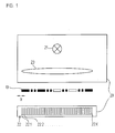
- FIG. 1 shows a first exemplary embodiment in a schematic form Position measuring device according to the invention including a first embodiment of the scale according to the invention.
- the position measuring device - Designed as a linear transmitted light system - includes here a scale 1, the specific training in the course of the following Description will be explained in detail, as well as a relative to Scale 1 in at least one measuring direction x movable scanning unit 20.
- the light source 21 comes at this point an LED, for example, a photodiode array serves as the detector arrangement 22 with k adjacent detector elements 22.1, .... 22.k.
- the scale 1 and the scanning unit 20 of the position measuring device are connected to two objects which are movable relative to one another in the measuring direction x and whose position relative to one another is to be determined.
- the two objects can be, for example, a tool and a workpiece in a numerically controlled machine tool.
- high-resolution absolute position information POS ABS can be generated by photoelectric scanning on a scale of 1 and the subsequent combination of the various generated scanning signals.
- An absolute position signal ABS, a coarse incremental signal INC G and a fine incremental signal INC F result as scanning signals, which will be explained in detail below.
- the combination of the different scanning signals to form an absolute position information item POS ABS can take place both directly in the position measuring device according to the invention and only in a downstream evaluation unit (not shown) to which the various scanning signals are fed.
- a downstream evaluation unit can be, for example, a numerical machine tool control.
- FIG. 2 shows a plan view of part of a scale 10 in connection with a schematically indicated detector arrangement 2 suitable for scanning.
- the scale 10 has first, second and third partial areas TB1, TB2, TB3 arranged along the measuring direction x, all of which have the same width b TB in the measuring direction x but different optical properties.
- the first partial areas TB1 are opaque
- the second partial areas TB2 are completely transparent.
- a third category of sub-areas TB3 is provided on the scale.
- the third sub-areas TB3 in turn have a different optical property to the first and second sub-areas TB1, TB2.
- the third partial areas TB3 are designed to be semi-transparent and thus have an optical property that lies between the transmission characteristics of the first and second partial areas TB1, TB2 with regard to the optical transmission characteristic. Because of the opaque or completely permeable design mentioned, these have complementary optical properties.
- the first partial areas TB1 are arranged periodically on the scale 10 along the measurement direction x.
- the scale 10 shown basically has a so-called Manchester coding on. This means that two different combinations two successive, different sub-areas TB3, TB1 or TB2, TB1 are each clearly assigned a logical signal.
- the section of the scale 10 shown in FIG. 2 results thus starting from the left as a sequence of the various logical signals as indicated, the bit sequence or bit word 1; 1; 0; 0; etc.
- Sequence of several logical signals ZERO (0) and ONE (1) can be along the scale 10 in the measuring direction x in a known manner characterize a unique absolute position as a code word or an absolute position signal Generate ABS.
- sequence several logical signals correspond to pseudo-random coding, from which a defined absolute position along the scale 10 can be derived.
- the different ones are involved optical properties of the various sub-areas TB1, TB2, TB3 around different optical transmissions; the first and second sub-areas TB1, TB2 have mutually complementary ones optical properties, which in turn is the formation of the first sub-areas TB1 as completely opaque or the second partial areas TB2 as complete permeable.
- the training of Transmitted light systems can of course be used to train the sub-areas TB1, TB2 as completely opaque sections or completely permeable Subareas also take place in reverse to the variant explained.
- a detector arrangement 2 is provided on the scanning unit side, which comprises a series of detector elements 2.1 - 2.12 arranged periodically in the measuring direction x.
- the coarse incremental signal INC G has a signal period SP G , which is derived in a known manner from the coarse division period TP G of the first partial areas TB1 on a scale 10.
- the coarse incremental signal INC G generated in this way can then be combined in a known manner with the absolute position signal POS to form a higher-resolution absolute position value POS ABS .
- FIGS. 3A and 3B A possible connection variant for the detector elements 2.1 - 2.12 of the example from FIG. 2 is shown schematically in FIGS. 3A and 3B.
- the two FIGS. 3A and 3B each show the interconnection required to generate the coarse incremental signal INC G and the interconnection to generate the absolute position signal ABS.
- the connection variants were shown in separate figures.
- reference numerals 3.1-3.4 each indicate summation elements which sum up scanning signals from in-phase detector elements 2.1-2.12 to the sum signals S1-S4;
- Reference numerals 4.1, 4.2 denote difference-forming elements which generate the two coarse incremental signals INC G, 0 and INC G, 90 from the four sum signals S1-S4 in a known manner.
- the first step is to generate the absolute position signal ABS provided the scanning signals of the detector elements 2.1, 2.3 a Summation element 3.5 and the scanning signals of the detector elements 2.2, 2.4 to supply a summation element 3.6, which on the output side Deliver sum signals S5, S6.
- the difference-forming elements are used D1, D2 the generation of difference signals DIF1, DIF2 the scanning signals of the detector elements 2.1, 2.3 and 2.2, 2.4.
- the sum and difference signals S5, S6, D1, D2 then become four evaluation elements K1 - K4 supplied, for example as comparators with predetermined Comparator thresholds are formed and in which the specified Assignments are made.
- the creation of one or two Error signals F ', F " are provided.
- the sum signals S5, S6 in the two evaluation elements K1, K2 according to the specified conditions evaluated and those supplied by the evaluation elements K1, K2 Output signals subsequently with the generated partial absolute position signals ABS ', ABS "of the evaluation elements K3, K4 the linking elements 5.1, 5.2 fed.
- the error signals F ', F " After the XOR link there result on the output side the error signals F ', F ", the values of Can accept 0 or 1.
- FIG. 4 shows, analogous to the figure described above, a plan view of part of a scale 10 'in connection with a schematically indicated detector arrangement 22', which can be used in a linear transmitted light position measuring device.
- a schematically indicated detector arrangement 22' which can be used in a linear transmitted light position measuring device.
- three partial areas TB1 ', TB2', TB3 'with different optical properties are again arranged along the measuring direction x.
- the first and second sub-areas TB1 ', TB2' are, as in the example explained above, completely opaque or completely transparent.
- the third sub-areas TB3 ' have a periodic sub-division, which in turn consist of first and second sub-sub-areas TB SUB1 , TB SUB2 arranged periodically in the measuring direction x with different optical properties.
- the first and second sub-areas TB SUB1 , TB SUB2 are opaque and completely transparent in the example shown; the period of the arrangement of the first and second sub-areas TB SUB1 , TB SUB2 is referred to below as the fine division period TP F and indicates in the measuring direction x the extent of successive first and second sub-areas TB SUB1 , TB SUB2 .
- this variant of a scale 10 'according to the invention also allows the generation of a fine incremental signal INC F , the resolution of which is higher than that of the Coarse-incremental signals INC G is.
- the formation of the absolute position value POS ABS is therefore possible with further increased accuracy.
- a so-called single-field scanning also results when the various incremental signals INC G , INC F are generated.
- This is to be understood as a sampling in which all phase-shifted signal components of the incremental signals INC G or INC F result from the sampling of a single division period TP G or TP F on the 10 'scale.
- a crucial advantage of such a scanning is its insensitivity to local scale contamination, since then all phase-shifted partial signals that contribute to the different incremental signals INC G , INC F are always influenced uniformly.
- the scale according to the invention in conjunction with certain scanning-side measures - which will be explained below - allows the generation of a coarse incremental signal INC G and a fine incremental signal INC F as already mentioned.
- a coarse incremental signal INC G or INC F we will always speak of a coarse or a fine incremental signal INC G or INC F , although in practice a pair of such signals is usually generated in each case, which have a phase shift of 90 ° to one another.
- the coarse incremental signal INC G results from the scanning of the partial areas TB3 'periodically arranged with the coarse division period TP G on a scale 10', in which case the third partial areas TB3 'are now periodically arranged accordingly.
- the fine incremental signal INC F is generated by scanning the sub-division structure in the third sub-regions TB3 ', where there is a periodic arrangement of sub-sub-regions with the fine division period TP F.
- N 16 detector elements are arranged on the detection side per coarse division period TP G.
- At least four detector elements must therefore be arranged per division period in order to ensure single-field sampling when the intended generation of four phase-shifted scanning signals from a single division period.
- a coarse incremental signal INC G is generated in accordance with the example above, at least four detector elements must be arranged per coarse division period TP G or an integer multiple thereof.
- a fine incremental signal INC F it is to be ensured analogously to this that at least four detector elements are arranged in the measuring direction per fine division period TP F or possibly an integral multiple thereof.
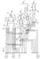
- the reference symbols 23.1-23.17 are in the circuit diagram of FIG. 5 each denotes summation elements which add up the respective Make signals present on the input side. About those with the reference numerals 24.1 - 24.5 designated difference formation elements takes place a subtraction or difference formation of the signals present at the beginning. With the help of the reference numbers 25.1 - 25.5 or 26.1, 26.2 The specified arithmetic operation takes place with the elements applied input signals.
- At least 16 detector elements and the corresponding interconnection thereof are required in the present example, for example the detector elements 22.1 '- 22.16'.
- the second to fourth blocks further provided in the example, each with 16 further detector elements 22.17 '- 22.32', 22.33 '- 22.48' and 22.49 '- 22.64', provide in principle the identical scanning information during scanning and merely improve the resulting signal strength during scanning. That is, every sixteenth detector element provides the in-phase scanning information.
- the resulting ones are used for circuitry implementation Scanning signals of the first eight detector elements 22.1 '- 22.8' the summation element 23.1 summed up to the signal S1, the scanning signals the second eight detector elements 22.9 '- 22.16' via the second summation element 23.2 for signal S2.
- From the summed signals S1, S2 is the difference signal with the help of the difference-forming element 24.1 DIF formed; with the help of the summation element 23.17 Sum signal SUM.
- the sum signal SUM and the difference signal are thereupon a link element 27 is fed by an XOR link of the signals DIF and SUM according to the previously explained assignment rules he follows.
- the absolute position signal ABS which can be further processed or the corresponding ones Bit values or logic signals.
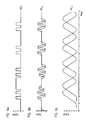
- FIGS. 5a - 5c The scanning signals ABS, INC G and INC F resulting from such an interconnection of the detector elements 22.1 - 22.64 or the corresponding signal pairs INC F, 0 and INC F, 90 ABS, INC G, 0 and INC F are shown in FIGS. 5a - 5c ,
- a scanning grid is arranged which e.g. as a phase grating is trained.
- a so-called vernier beat in the detection plane in a known manner produce. From this vernier beat, in turn, derive an incremental signal with a defined signal period.
Applications Claiming Priority (2)
| Application Number | Priority Date | Filing Date | Title |
|---|---|---|---|
| DE10201496A DE10201496A1 (de) | 2002-01-17 | 2002-01-17 | Maßstab und Positionsmesseinrichtung zur absoluten Positionsbestimmung |
| DE10201496 | 2002-01-17 |
Publications (2)
| Publication Number | Publication Date |
|---|---|
| EP1329696A1 true EP1329696A1 (fr) | 2003-07-23 |
| EP1329696B1 EP1329696B1 (fr) | 2008-07-16 |
Family
ID=7712298
Family Applications (1)
| Application Number | Title | Priority Date | Filing Date |
|---|---|---|---|
| EP02026729A Expired - Lifetime EP1329696B1 (fr) | 2002-01-17 | 2002-11-30 | Détecteur de position absolue avec échelle |
Country Status (6)
| Country | Link |
|---|---|
| US (1) | US6742275B2 (fr) |
| EP (1) | EP1329696B1 (fr) |
| JP (1) | JP4620330B2 (fr) |
| AT (1) | ATE401554T1 (fr) |
| DE (2) | DE10201496A1 (fr) |
| ES (1) | ES2307703T3 (fr) |
Cited By (4)
| Publication number | Priority date | Publication date | Assignee | Title |
|---|---|---|---|---|
| EP1983308A1 (fr) | 2007-04-20 | 2008-10-22 | Dr. Johannes Heidenhain GmbH | Dispositif de mesure de position |
| WO2009132901A1 (fr) * | 2008-05-02 | 2009-11-05 | Dr. Johannes Heidenhain Gmbh | Dispositif de mesure de position |
| CN102003976A (zh) * | 2010-08-27 | 2011-04-06 | 中国科学院长春光学精密机械与物理研究所 | 单码道绝对位置编码方法、解码方法及测量装置 |
| EP2963393A1 (fr) * | 2014-07-01 | 2016-01-06 | Canon Kabushiki Kaisha | Codeur absolu |
Families Citing this family (21)
| Publication number | Priority date | Publication date | Assignee | Title |
|---|---|---|---|---|
| DE50203793D1 (de) * | 2002-01-17 | 2005-09-01 | Heidenhain Gmbh Dr Johannes | Positionsmesseinrichtung |
| US20050094159A1 (en) * | 2003-10-29 | 2005-05-05 | Wen-Wei Su | Angle detecting sensor and vehicular controlling system using the same |
| EP1593935A1 (fr) * | 2004-05-06 | 2005-11-09 | Leica Geosystems AG | Jalon étalonné, appareil de mesure des niveaux et méthode de détermination des niveaux utilisant cet étalon |
| GB0413711D0 (en) * | 2004-06-21 | 2004-07-21 | Renishaw Plc | Scale and readhead apparatus |
| DE102005009043A1 (de) * | 2005-02-22 | 2006-08-31 | Dr. Johannes Heidenhain Gmbh | Abtasteinheit für eine Positionsmesseinrichtung |
| DE102005047009A1 (de) * | 2005-09-30 | 2007-04-05 | Bosch Rexroth Mechatronics Gmbh | Absolutes Positionsmesssystem |
| DE102006007184A1 (de) * | 2006-02-15 | 2007-08-16 | Dr. Johannes Heidenhain Gmbh | Positionsmesseinrichtung |
| JP4953653B2 (ja) * | 2006-02-15 | 2012-06-13 | 株式会社ミツトヨ | 光電式エンコーダ |
| DE102006021484A1 (de) * | 2006-05-09 | 2007-11-15 | Dr. Johannes Heidenhain Gmbh | Optische Positionsmesseinrichtung |
| JP4976823B2 (ja) * | 2006-11-15 | 2012-07-18 | 株式会社ミツトヨ | 光学式エンコーダ |
| DE102007045362A1 (de) | 2007-09-22 | 2009-04-02 | Dr. Johannes Heidenhain Gmbh | Positionsmesseinrichtung |
| DE102007061287A1 (de) * | 2007-12-19 | 2009-06-25 | Dr. Johannes Heidenhain Gmbh | Positionsmesseinrichtung und Verfahren zur absoluten Positionsbestimmung |
| EP2175243B1 (fr) | 2008-10-09 | 2015-08-12 | Delphi Technologies, Inc. | Codeur de position à haute résolution |
| EP2199752B1 (fr) * | 2008-12-17 | 2019-08-28 | Fagor, S.Coop. | Codeur de position absolue |
| GB0903535D0 (en) * | 2009-03-02 | 2009-04-08 | Rls Merilna Tehnika D O O | Encoder readhead |
| GB0906257D0 (en) | 2009-04-08 | 2009-05-20 | Renishaw Plc | Position encoder apparatus |
| GB0906258D0 (en) | 2009-04-08 | 2009-05-20 | Renishaw Plc | Position encoder apparatus |
| JP5439163B2 (ja) * | 2009-12-25 | 2014-03-12 | オリンパス株式会社 | 光学式信号出力装置の信号処理装置及び光学式変位検出装置 |
| DE102016214456A1 (de) * | 2016-08-04 | 2018-02-08 | Dr. Johannes Heidenhain Gesellschaft Mit Beschränkter Haftung | Positionsmesseinrichtung und Verfahren zum Betreiben einer Positionsmesseinrichtung |
| JP7443140B2 (ja) * | 2020-04-09 | 2024-03-05 | Dmg森精機株式会社 | 位置検出装置 |
| EP4239296A1 (fr) | 2022-03-04 | 2023-09-06 | KappaSense Ltd | Codeur capacitif à échelle codée |
Citations (3)
| Publication number | Priority date | Publication date | Assignee | Title |
|---|---|---|---|---|
| US4774494A (en) * | 1985-08-01 | 1988-09-27 | Lucas Industries Public Limited Company | Position encoder employing three or more colors |
| EP0635700A1 (fr) * | 1993-07-22 | 1995-01-25 | Marco Dr. Brandestini | Codeur digital absolu de position |
| GB2297840A (en) * | 1995-02-09 | 1996-08-14 | R D P Electronics Limited | Displacement sensor having a grating with an antisymmetric periodic pattern |
Family Cites Families (15)
| Publication number | Priority date | Publication date | Assignee | Title |
|---|---|---|---|---|
| JPS5957652A (ja) * | 1982-09-27 | 1984-04-03 | 松崎 住市 | 遮蔽材を周設した保護眼鏡 |
| SE460928B (sv) * | 1986-10-13 | 1989-12-04 | Johansson Ab C E | Absolutmaetande skalsystem |
| JPH04346029A (ja) * | 1991-05-24 | 1992-12-01 | Nippon Telegr & Teleph Corp <Ntt> | 光学式エンコ―ダ |
| US5519393A (en) * | 1993-07-22 | 1996-05-21 | Bouens, Inc. | Absolute digital position encoder with multiple sensors per track |
| US5739775A (en) * | 1993-07-22 | 1998-04-14 | Bourns, Inc. | Digital input and control device |
| US5880683A (en) * | 1993-07-22 | 1999-03-09 | Bourns, Inc. | Absolute digital position encoder |
| DE4428590C2 (de) * | 1994-08-12 | 1996-06-20 | Heidenhain Gmbh Dr Johannes | Positionsmeßeinrichtung |
| DE19641035C2 (de) * | 1996-10-04 | 1999-09-16 | Heidenhain Gmbh Dr Johannes | Vorrichtung und Verfahren zur Positionsmessung |
| CN1090755C (zh) * | 1997-02-03 | 2002-09-11 | 株式会社索佳 | 电子水准仪 |
| JPH10221652A (ja) * | 1997-02-10 | 1998-08-21 | Yasushige Une | 眼鏡保護カバー |
| JP2000018971A (ja) * | 1998-06-30 | 2000-01-21 | Toshiba Corp | エンコーダ |
| DE19912310B4 (de) * | 1999-03-19 | 2007-11-29 | Dr. Johannes Heidenhain Gmbh | Positionsmeßeinrichtung |
| DE19941318A1 (de) * | 1999-08-31 | 2001-03-15 | Heidenhain Gmbh Dr Johannes | Optische Positionsmeßeinrichtung |
| DE29916394U1 (de) * | 1999-09-17 | 2001-02-15 | Heidenhain Gmbh Dr Johannes | Optische Positionsmeßeinrichtung |
| DE10117193B4 (de) * | 2001-04-05 | 2013-04-04 | Anton Rodi | Messsystem zur Absolutwerterfassung von Winkeln oder Wegen |
-
2002
- 2002-01-17 DE DE10201496A patent/DE10201496A1/de not_active Withdrawn
- 2002-11-30 AT AT02026729T patent/ATE401554T1/de not_active IP Right Cessation
- 2002-11-30 DE DE50212504T patent/DE50212504D1/de not_active Expired - Lifetime
- 2002-11-30 ES ES02026729T patent/ES2307703T3/es not_active Expired - Lifetime
- 2002-11-30 EP EP02026729A patent/EP1329696B1/fr not_active Expired - Lifetime
-
2003
- 2003-01-08 JP JP2003002452A patent/JP4620330B2/ja not_active Expired - Fee Related
- 2003-01-16 US US10/345,841 patent/US6742275B2/en not_active Expired - Lifetime
Patent Citations (3)
| Publication number | Priority date | Publication date | Assignee | Title |
|---|---|---|---|---|
| US4774494A (en) * | 1985-08-01 | 1988-09-27 | Lucas Industries Public Limited Company | Position encoder employing three or more colors |
| EP0635700A1 (fr) * | 1993-07-22 | 1995-01-25 | Marco Dr. Brandestini | Codeur digital absolu de position |
| GB2297840A (en) * | 1995-02-09 | 1996-08-14 | R D P Electronics Limited | Displacement sensor having a grating with an antisymmetric periodic pattern |
Cited By (10)
| Publication number | Priority date | Publication date | Assignee | Title |
|---|---|---|---|---|
| EP1983308A1 (fr) | 2007-04-20 | 2008-10-22 | Dr. Johannes Heidenhain GmbH | Dispositif de mesure de position |
| US8820623B2 (en) | 2007-04-20 | 2014-09-02 | Dr. Johannes Heidenhain Gmbh | Position-measuring device |
| WO2009132901A1 (fr) * | 2008-05-02 | 2009-11-05 | Dr. Johannes Heidenhain Gmbh | Dispositif de mesure de position |
| DE102008022027A1 (de) | 2008-05-02 | 2009-11-05 | Dr. Johannes Heidenhain Gmbh | Positionsmesseinrichtung |
| US8570621B2 (en) | 2008-05-02 | 2013-10-29 | Dr. Johannes Heidenhain Gmbh | Position measuring device |
| CN102037332B (zh) * | 2008-05-02 | 2014-08-13 | 约翰内斯·海德汉博士有限公司 | 位置测量设备 |
| CN102003976A (zh) * | 2010-08-27 | 2011-04-06 | 中国科学院长春光学精密机械与物理研究所 | 单码道绝对位置编码方法、解码方法及测量装置 |
| CN102003976B (zh) * | 2010-08-27 | 2012-07-25 | 中国科学院长春光学精密机械与物理研究所 | 单码道绝对位置编码方法、解码方法及测量装置 |
| EP2963393A1 (fr) * | 2014-07-01 | 2016-01-06 | Canon Kabushiki Kaisha | Codeur absolu |
| US9880028B2 (en) | 2014-07-01 | 2018-01-30 | Canon Kabushiki Kaisha | Absolute encoder |
Also Published As
| Publication number | Publication date |
|---|---|
| ATE401554T1 (de) | 2008-08-15 |
| US20030145479A1 (en) | 2003-08-07 |
| DE50212504D1 (de) | 2008-08-28 |
| US6742275B2 (en) | 2004-06-01 |
| JP4620330B2 (ja) | 2011-01-26 |
| ES2307703T3 (es) | 2008-12-01 |
| EP1329696B1 (fr) | 2008-07-16 |
| DE10201496A1 (de) | 2003-07-31 |
| JP2003247866A (ja) | 2003-09-05 |
Similar Documents
| Publication | Publication Date | Title |
|---|---|---|
| EP1329696B1 (fr) | Détecteur de position absolue avec échelle | |
| EP1821073B1 (fr) | Dispositif de mesure de position | |
| EP1111345A2 (fr) | Dispositif de mesure de position | |
| DE4123722B4 (de) | Absolutkodierer | |
| EP1468254B1 (fr) | Dispositif de mesure de position | |
| DE3416864C2 (de) | Photoelektrische Meßeinrichtung | |
| DE4436784B4 (de) | Absolutes Positionsmeßsystem | |
| WO1999008074A1 (fr) | Unite de balayage pour dispositif optique de mesure de position | |
| DE10244234A1 (de) | Positionsmesseinrichtung | |
| DE3308814A1 (de) | Messeinrichtung | |
| DE10132521A1 (de) | Positionsmesseinrichtung | |
| EP1271107B1 (fr) | Dispositif de mesure de position | |
| DE10041507A1 (de) | Lenkwinkelsensor für Kraftfahrzeuge | |
| DE10028136A1 (de) | Positionsmeßsystem | |
| DE3221982A1 (de) | Optisches inkrementalcodiersystem mit adressierbarem index | |
| DE102008053985A1 (de) | Absolute Winkelcodierung und Winkelmessvorrichtung | |
| EP1195579A2 (fr) | Procédé et dispositif de détermination de la position absolue | |
| DE3001794A1 (de) | Verfahren fuer die ablesung von anzeigen von mehrskalen-codiergeraeten und mehrtouriger absoluter winkel-code-umsetzer | |
| EP2340417B1 (fr) | Dispositif de mesure de position absolue | |
| DE3337653C2 (fr) | ||
| WO2001084084A1 (fr) | Unite de balayage pour dispositif de mesure optique de la position | |
| EP1427985A1 (fr) | Dispositif de mesure de position et procede pour l'exploitation d'un dispositif de mesure de position | |
| DE10244235A1 (de) | Positionsmesseinrichtung | |
| WO2010049046A1 (fr) | Dispositif de mesure de position absolue | |
| DE19716058B4 (de) | Optische Positionsmeßeinrichtung |
Legal Events
| Date | Code | Title | Description |
|---|---|---|---|
| PUAI | Public reference made under article 153(3) epc to a published international application that has entered the european phase |
Free format text: ORIGINAL CODE: 0009012 |
|
| AK | Designated contracting states |
Designated state(s): AT BE BG CH CY CZ DE DK EE ES FI FR GB GR IE IT LI LU MC NL PT SE SK TR |
|
| AX | Request for extension of the european patent |
Extension state: AL LT LV MK RO SI |
|
| 17P | Request for examination filed |
Effective date: 20040123 |
|
| AKX | Designation fees paid |
Designated state(s): AT BE BG CH CY CZ DE DK EE ES FI FR GB GR IE IT LI LU MC NL PT SE SK TR |
|
| 17Q | First examination report despatched |
Effective date: 20040907 |
|
| GRAP | Despatch of communication of intention to grant a patent |
Free format text: ORIGINAL CODE: EPIDOSNIGR1 |
|
| GRAS | Grant fee paid |
Free format text: ORIGINAL CODE: EPIDOSNIGR3 |
|
| GRAA | (expected) grant |
Free format text: ORIGINAL CODE: 0009210 |
|
| AK | Designated contracting states |
Kind code of ref document: B1 Designated state(s): AT BE BG CH CY CZ DE DK EE ES FI FR GB GR IE IT LI LU MC NL PT SE SK TR |
|
| REG | Reference to a national code |
Ref country code: GB Ref legal event code: FG4D Free format text: NOT ENGLISH |
|
| REG | Reference to a national code |
Ref country code: CH Ref legal event code: EP |
|
| REF | Corresponds to: |
Ref document number: 50212504 Country of ref document: DE Date of ref document: 20080828 Kind code of ref document: P |
|
| REG | Reference to a national code |
Ref country code: IE Ref legal event code: FG4D Free format text: LANGUAGE OF EP DOCUMENT: GERMAN |
|
| REG | Reference to a national code |
Ref country code: ES Ref legal event code: FG2A Ref document number: 2307703 Country of ref document: ES Kind code of ref document: T3 |
|
| NLV1 | Nl: lapsed or annulled due to failure to fulfill the requirements of art. 29p and 29m of the patents act | ||
| PG25 | Lapsed in a contracting state [announced via postgrant information from national office to epo] |
Ref country code: NL Free format text: LAPSE BECAUSE OF FAILURE TO SUBMIT A TRANSLATION OF THE DESCRIPTION OR TO PAY THE FEE WITHIN THE PRESCRIBED TIME-LIMIT Effective date: 20080716 Ref country code: PT Free format text: LAPSE BECAUSE OF FAILURE TO SUBMIT A TRANSLATION OF THE DESCRIPTION OR TO PAY THE FEE WITHIN THE PRESCRIBED TIME-LIMIT Effective date: 20081216 |
|
| PG25 | Lapsed in a contracting state [announced via postgrant information from national office to epo] |
Ref country code: BG Free format text: LAPSE BECAUSE OF FAILURE TO SUBMIT A TRANSLATION OF THE DESCRIPTION OR TO PAY THE FEE WITHIN THE PRESCRIBED TIME-LIMIT Effective date: 20081016 Ref country code: FI Free format text: LAPSE BECAUSE OF FAILURE TO SUBMIT A TRANSLATION OF THE DESCRIPTION OR TO PAY THE FEE WITHIN THE PRESCRIBED TIME-LIMIT Effective date: 20080716 |
|
| REG | Reference to a national code |
Ref country code: IE Ref legal event code: FD4D |
|
| PG25 | Lapsed in a contracting state [announced via postgrant information from national office to epo] |
Ref country code: IE Free format text: LAPSE BECAUSE OF FAILURE TO SUBMIT A TRANSLATION OF THE DESCRIPTION OR TO PAY THE FEE WITHIN THE PRESCRIBED TIME-LIMIT Effective date: 20080716 Ref country code: EE Free format text: LAPSE BECAUSE OF FAILURE TO SUBMIT A TRANSLATION OF THE DESCRIPTION OR TO PAY THE FEE WITHIN THE PRESCRIBED TIME-LIMIT Effective date: 20080716 Ref country code: DK Free format text: LAPSE BECAUSE OF FAILURE TO SUBMIT A TRANSLATION OF THE DESCRIPTION OR TO PAY THE FEE WITHIN THE PRESCRIBED TIME-LIMIT Effective date: 20080716 |
|
| PLBE | No opposition filed within time limit |
Free format text: ORIGINAL CODE: 0009261 |
|
| STAA | Information on the status of an ep patent application or granted ep patent |
Free format text: STATUS: NO OPPOSITION FILED WITHIN TIME LIMIT |
|
| PG25 | Lapsed in a contracting state [announced via postgrant information from national office to epo] |
Ref country code: CZ Free format text: LAPSE BECAUSE OF FAILURE TO SUBMIT A TRANSLATION OF THE DESCRIPTION OR TO PAY THE FEE WITHIN THE PRESCRIBED TIME-LIMIT Effective date: 20080716 Ref country code: SK Free format text: LAPSE BECAUSE OF FAILURE TO SUBMIT A TRANSLATION OF THE DESCRIPTION OR TO PAY THE FEE WITHIN THE PRESCRIBED TIME-LIMIT Effective date: 20080716 |
|
| BERE | Be: lapsed |
Owner name: DR. JOHANNES HEIDENHAIN G.M.B.H. Effective date: 20081130 |
|
| 26N | No opposition filed |
Effective date: 20090417 |
|
| PG25 | Lapsed in a contracting state [announced via postgrant information from national office to epo] |
Ref country code: MC Free format text: LAPSE BECAUSE OF NON-PAYMENT OF DUE FEES Effective date: 20081130 |
|
| REG | Reference to a national code |
Ref country code: CH Ref legal event code: PL |
|
| PG25 | Lapsed in a contracting state [announced via postgrant information from national office to epo] |
Ref country code: BE Free format text: LAPSE BECAUSE OF NON-PAYMENT OF DUE FEES Effective date: 20081130 |
|
| PG25 | Lapsed in a contracting state [announced via postgrant information from national office to epo] |
Ref country code: LI Free format text: LAPSE BECAUSE OF NON-PAYMENT OF DUE FEES Effective date: 20081130 Ref country code: CH Free format text: LAPSE BECAUSE OF NON-PAYMENT OF DUE FEES Effective date: 20081130 |
|
| PG25 | Lapsed in a contracting state [announced via postgrant information from national office to epo] |
Ref country code: SE Free format text: LAPSE BECAUSE OF FAILURE TO SUBMIT A TRANSLATION OF THE DESCRIPTION OR TO PAY THE FEE WITHIN THE PRESCRIBED TIME-LIMIT Effective date: 20081016 Ref country code: AT Free format text: LAPSE BECAUSE OF NON-PAYMENT OF DUE FEES Effective date: 20081130 |
|
| PG25 | Lapsed in a contracting state [announced via postgrant information from national office to epo] |
Ref country code: LU Free format text: LAPSE BECAUSE OF NON-PAYMENT OF DUE FEES Effective date: 20081130 Ref country code: CY Free format text: LAPSE BECAUSE OF FAILURE TO SUBMIT A TRANSLATION OF THE DESCRIPTION OR TO PAY THE FEE WITHIN THE PRESCRIBED TIME-LIMIT Effective date: 20080716 |
|
| PG25 | Lapsed in a contracting state [announced via postgrant information from national office to epo] |
Ref country code: TR Free format text: LAPSE BECAUSE OF FAILURE TO SUBMIT A TRANSLATION OF THE DESCRIPTION OR TO PAY THE FEE WITHIN THE PRESCRIBED TIME-LIMIT Effective date: 20080716 |
|
| PG25 | Lapsed in a contracting state [announced via postgrant information from national office to epo] |
Ref country code: GR Free format text: LAPSE BECAUSE OF FAILURE TO SUBMIT A TRANSLATION OF THE DESCRIPTION OR TO PAY THE FEE WITHIN THE PRESCRIBED TIME-LIMIT Effective date: 20081017 |
|
| PGFP | Annual fee paid to national office [announced via postgrant information from national office to epo] |
Ref country code: FR Payment date: 20121130 Year of fee payment: 11 |
|
| PGFP | Annual fee paid to national office [announced via postgrant information from national office to epo] |
Ref country code: IT Payment date: 20121127 Year of fee payment: 11 |
|
| REG | Reference to a national code |
Ref country code: FR Ref legal event code: ST Effective date: 20140731 |
|
| PG25 | Lapsed in a contracting state [announced via postgrant information from national office to epo] |
Ref country code: IT Free format text: LAPSE BECAUSE OF NON-PAYMENT OF DUE FEES Effective date: 20131130 |
|
| PG25 | Lapsed in a contracting state [announced via postgrant information from national office to epo] |
Ref country code: FR Free format text: LAPSE BECAUSE OF NON-PAYMENT OF DUE FEES Effective date: 20131202 |
|
| PGFP | Annual fee paid to national office [announced via postgrant information from national office to epo] |
Ref country code: ES Payment date: 20151111 Year of fee payment: 14 |
|
| PG25 | Lapsed in a contracting state [announced via postgrant information from national office to epo] |
Ref country code: ES Free format text: LAPSE BECAUSE OF NON-PAYMENT OF DUE FEES Effective date: 20161130 |
|
| REG | Reference to a national code |
Ref country code: ES Ref legal event code: FD2A Effective date: 20181116 |
|
| PG25 | Lapsed in a contracting state [announced via postgrant information from national office to epo] |
Ref country code: ES Free format text: LAPSE BECAUSE OF NON-PAYMENT OF DUE FEES Effective date: 20161201 |
|
| PGFP | Annual fee paid to national office [announced via postgrant information from national office to epo] |
Ref country code: GB Payment date: 20191120 Year of fee payment: 18 |
|
| PGFP | Annual fee paid to national office [announced via postgrant information from national office to epo] |
Ref country code: DE Payment date: 20201119 Year of fee payment: 19 |
|
| GBPC | Gb: european patent ceased through non-payment of renewal fee |
Effective date: 20201130 |
|
| PG25 | Lapsed in a contracting state [announced via postgrant information from national office to epo] |
Ref country code: GB Free format text: LAPSE BECAUSE OF NON-PAYMENT OF DUE FEES Effective date: 20201130 |
|
| REG | Reference to a national code |
Ref country code: DE Ref legal event code: R119 Ref document number: 50212504 Country of ref document: DE |
|
| PG25 | Lapsed in a contracting state [announced via postgrant information from national office to epo] |
Ref country code: DE Free format text: LAPSE BECAUSE OF NON-PAYMENT OF DUE FEES Effective date: 20220601 |