EP1329338A2 - Schreibgerät - Google Patents
Schreibgerät Download PDFInfo
- Publication number
- EP1329338A2 EP1329338A2 EP02028563A EP02028563A EP1329338A2 EP 1329338 A2 EP1329338 A2 EP 1329338A2 EP 02028563 A EP02028563 A EP 02028563A EP 02028563 A EP02028563 A EP 02028563A EP 1329338 A2 EP1329338 A2 EP 1329338A2
- Authority
- EP
- European Patent Office
- Prior art keywords
- writing instrument
- tip
- writing
- sleeve
- cap
- Prior art date
- Legal status (The legal status is an assumption and is not a legal conclusion. Google has not performed a legal analysis and makes no representation as to the accuracy of the status listed.)
- Granted
Links
Images


Classifications
-
- B—PERFORMING OPERATIONS; TRANSPORTING
- B43—WRITING OR DRAWING IMPLEMENTS; BUREAU ACCESSORIES
- B43K—IMPLEMENTS FOR WRITING OR DRAWING
- B43K24/00—Mechanisms for selecting, projecting, retracting or locking writing units
- B43K24/02—Mechanisms for selecting, projecting, retracting or locking writing units for locking a single writing unit in only fully projected or retracted positions
- B43K24/04—Mechanisms for selecting, projecting, retracting or locking writing units for locking a single writing unit in only fully projected or retracted positions operated by means sliding in longitudinally-slotted casings
-
- B—PERFORMING OPERATIONS; TRANSPORTING
- B43—WRITING OR DRAWING IMPLEMENTS; BUREAU ACCESSORIES
- B43K—IMPLEMENTS FOR WRITING OR DRAWING
- B43K24/00—Mechanisms for selecting, projecting, retracting or locking writing units
- B43K24/02—Mechanisms for selecting, projecting, retracting or locking writing units for locking a single writing unit in only fully projected or retracted positions
- B43K24/08—Mechanisms for selecting, projecting, retracting or locking writing units for locking a single writing unit in only fully projected or retracted positions operated by push-buttons
Definitions
- a writing instrument which has an outer sleeve, in the interior of which a Mine is axially movable, which is in a tip of the writing instrument is stored is known.
- a disadvantage of such a writing instrument is that its length in writing is essentially equal to the length is in the closed state.
- the construction of this writing instrument enables namely, it does not adversely affect the length of the Writing instrument of the kind necessary for its ergonomic handling Length in the writing state to a smaller length in the closed state shorten the writing instrument, but what of a variety is increasingly demanded by customers because they want a compact one when closed and therefore easy to insert To have writing utensils.
- a writing instrument which has a cap, a handle and a Has tip that delimit an interior of the writing instrument, in a mine is recorded, the tip of the mine in a writing state of the writing instrument in front of the front end of the tip of the writing instrument and behind in a closed state of the writing instrument the front end of the tip of the writing instrument is known.
- adversely with this writing instrument is also that its length in the writing state is substantially equal to the length in the closed state.
- the construction of the known writing instrument makes it possible in disadvantageous way not the length of the writing instrument before the for its ergonomic handling required length in writing to a smaller length in the closed state of the writing instrument shorten what is increasing from a large number of customers is required because they want a compact in the closed state building and therefore easy to insert writing instrument.
- a writing instrument to further develop such that the writing instrument according to the invention in the closed state has a shorter length than when it is written.
- a writing instrument with an outer sleeve, in the interior of which a lead is axially movable is arranged, which is mounted in a tip of the writing instrument or a writing instrument, which has a cap, a handle and a tip has that limit an interior of the writing instrument, in which a Mine is recorded, the tip of the mine in a writing state of the Writing instrument in front of the front end of the tip of the writing instrument and in a closed state of the writing instrument behind it is located at the front end of the tip of the writing instrument, that the writing instrument can be used without the aid or acceptance of a existing cap in the closed state a shorter or lower Length than in the writing state.
- the writing instrument is designed in such a way that in the outer sleeve of the writing instrument an inner sleeve receiving the refill is arranged to be movable in the axial direction of the writing instrument, that the outer sleeve is a guide element for a connected to the inner sleeve Control element, and that by a movement of the Control the inner sleeve from a first end position in which the mine tip the lead behind the front end of the outer sleeve of the The writing instrument lies in a second end position in which the tip of the mine is in front the front end of the outer sleeve of the writing instrument is movable and that the inner sleeve can be fixed in position in this second end position.
- the measures according to the invention advantageously and Way a writing instrument is formed, which is characterized by that its length when closed is significantly less than its length Length in the writing state of the writing instrument according to the invention.
- a writing instrument is formed, which is characterized by that its length when closed is significantly less than its length Length in the writing state of the writing instrument according to the invention.
- a further embodiment according to the invention according to claim 3 exists in that the writing instrument is designed in such a way that the im Handle of the writing instrument, tip of the writing instrument between two end positions of the tip is slidably arranged, in which the first end position of the tip the lead tip of the recorded in the writing instrument Mine protrudes over the front end of the tip and in the second end position of the tip, the lead tip of the lead in the axial direction behind the front end of the tip of the writing instrument is that in the Cap of the writing instrument, a switching element is arranged through which the tip of the writing instrument can be acted on, so that at a corresponding axial movement of the cap to the tip of the writing instrument hin the switching element acts on the tip and this of their first end position moved to its second end position, and that the cap of the The writing instrument can be fixed in position in this position of the tip of the writing instrument is.
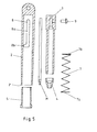
- FIGS. 1 and 2 is a first embodiment of a designated 1 Shown writing instrument, which is shown in FIGS. 1 and 2 in a Outer sleeve 2 and a slidably received in the outer sleeve 2
- Inner sleeve 3 with tip 4 is divided.
- a mine M is included, the mine tip M 'in the Tip 4 is stored.
- the inner sleeve 3 is in the outer sleeve 2 via a Guide sleeve 5 mounted, the rear end 5 'a stop surface for forms a first end 7a of a spring 7.
- a second stop surface for the spring 7 is formed by a circumferential step 3a of the inner sleeve 3.
- the outer sleeve 2 has a guide element 8 for with the inner sleeve 3 connected switching element 9.
- the guide element 8 has one in the axial direction first region 8a and a transverse to it extending second region 8b, in which in the case shown here as Switch pin 9 'formed switching element 9 is movable.
- the inner sleeve 3 In the closed state of the Writing instrument 1, the inner sleeve 3 by the force of the spring 7 in it held second end position in which the mine tip M 'of the mine M behind the front end 2 'of the outer sleeve 2.
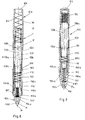
- FIGS. 5 and 6 is a second embodiment of a designated 101 Shown writing instrument, which according to FIGS. 5 and 6 in a handle 102, a cap 103 and a tip 104 is divided.
- the three The aforementioned components delimit an interior 101 'of the writing instrument 101, in which a mine M can be accommodated (FIGS. 8 and 9), the tip of which M 'in the writing state of writing device 101 shown in FIG. 5 protrudes over a front end 104 'of the tip 104 and in the closed state of the writing instrument 101 behind the front end 104 'of the tip 104 of the writing instrument 101 lies and is thus protected in whose interior 101 'is recorded.
- the mine tip M '- as can be seen in FIG. 5 - to move from its writing state to the inside of the tip 104 provided that the cap 103 axially in the direction of the handle 102 is shifted, which causes - as will be explained below -
- the tip 104 advanced in the axial direction of the writing instrument 101 and thus covers the mine tip M 'of the mine M.
- Such The approach does not only have the advantage that this makes it particularly simple way a protected recording of mine M in Interior 101 'of the writing instrument 101 can be achieved, but also that the length of the described in an advantageous manner Writing instrument 101 in its closed state shown in FIG. 2 is significantly shortened so that this then compact writing instrument 101 can be stored easily and in a space-saving manner after - as below also described in detail - the cap 103 in the in Fig. 7th position shown was locked.
- the tip 104 of the writing instrument 101 is tubular formed and axially displaceable in the handle 102 of the writing instrument 101 stored, at least from their first shown in Fig. 8 End position in its second end position shown in FIG. 9.
- a guide sleeve 110 is provided, a front Front part 110a on the inner wall facing end 104 'of tip 109 of the sleeve-shaped handle 102 rests and is preferably fixed connected to it. This ensures a safe arrangement of the guide sleeve 110a reached in the writing instrument 101.
- the front part 110a of the guide sleeve 110 goes over a step 110b into a rear part 110c, which is the actual guidance of the tubular tip 104 in the handle 102 of the writing instrument 101 is used, by the outer wall of the tubular portion 104b of the tip 104 the inner wall of the rear part 110c of the guide sleeve 110.
- the step 110b forms a stop for a front part 104a of the Tip 104 of the writing instrument 101.
- the step-like configuration of the guide sleeve 110 furthermore causes that the outer wall of the tubular part 104b of the tip 104 spaced from the inner wall of the handle 102, so that in these through the inner wall and the outer wall of the guide sleeve 110 limited space a front portion 6 'of a cap inner tube 106 of the cap 103 can be inserted.
- Control sleeve 107 arranged, the front end 107a on the outer wall of the rear part 110c of the guide sleeve 110 and preferably is firmly connected to this, whereby the control sleeve 107 in Interior 101 'of the writing instrument 101 is fixed in position.
- the control sleeve 107 serves on the one hand as a guide for the inner cap tube 106, so that the inner cap tube 106 and thus that with this inner cap tube 106 firmly connected actual cap part 103a of the cap 103 in its in 6 and 8 shown in its closed position shown in Fig. 7 is movable along the control sleeve 107.
- the control sleeve 107 also has a guide element 108 with a region 108a running in the axial direction for a here as Switch pin 109 'formed switching element 109, which with the Cap 103 is connected and serves to advance the cap 103 towards the handle 102 a rear end 104b 'of the tip 104 to act, causing the tip 104 of its shown in Fig. 8 Writing position in its shown in Fig. 9, opposite the writing position advanced closed position is moved by the guide member 108 in the longitudinal region 8a of the guide element 108 is moved.
- the cap 103 of the writing instrument 101 is locked in this closed position.
- the tip 104 of the writing instrument 101 is acted upon by a return spring 112 which is coaxial to the tubular part 104b of the tip 104 is arranged and causes the tip 104 in the closed state of the writing instrument 101 with a spring force acting in the direction of the cap 103 is applied.
- a return spring 112 which is coaxial to the tubular part 104b of the tip 104 is arranged and causes the tip 104 in the closed state of the writing instrument 101 with a spring force acting in the direction of the cap 103 is applied.
- Stop element 113 is provided, which has a first stop for the return spring 112 for the tip 104.
- a second The stop for the return spring 112 is located on the cap side End of the guide sleeve 110 is formed.
- Such a construction has the advantage that when opening of the writing instrument 101 described, which is easy to accomplish as a result is by the cap 103 against their previously described Direction of rotation is moved, which by this rotary movement Switching element 109 from the transverse region 108b in the in FIG region 108a of the guide element 108 extending in the axial direction is moved and a slight retraction of the cap 103 causes the application of the tip 104 by the switching element applied to it 9, the tip 104 is lifted from that shown in FIG second setting in with the writing state of the writing instrument 101 correlated first end position by the action of the return spring 112 is retrieved, which then leads the mine tip M 'of mine M in is in its read-ready state.
- the cap 103 can then again moved back to their starting position shown in Fig. 8 and through there suitable agents are fixed in position.
- cap spring 115 for moving the cap 103 back in which a cap spring 115 is arranged, which on the cap side End of the control sleeve 107 attaches and a driving force on the Exercises cap 103.
- the cap spring 115 causes that by their driving force, the cap 103 automatically from that shown in FIG. 9 Closed position moved to its writing position shown in Fig. 8 becomes.
- the cap spring 115 thus brings about an advantageous manner automatic opening of the writing instrument 101 described.
- a mine M Spacer spring 117 is provided, which on the one hand on the mine M and on the other hand attaches to a stop surface 117 'of the tip 104. hereby is the mine M in the axial direction against a cap on the Control sleeve 107 attached changing element 119 pressed.
- the spacer 117 advantageously causes the mine M in its defined position is held in the writing instrument 101, regardless of the respective position of the tip 104.
- the rear end of the cap part 103a of the cap 103 has a passage opening 118 through which the Changing element 119 is accessible.
Landscapes
- Mechanical Pencils And Projecting And Retracting Systems Therefor, And Multi-System Writing Instruments (AREA)
- Pens And Brushes (AREA)
Abstract
Description
- Fig. 1
- das Schreibgerät nach einer ersten Ausführungsform,
- Fig. 2
- das Schreibgerät gemäß Fig. 1,
- Fig. 3
- einen Längsschnitt durch das Schreibgerät gemäß Fig. 1,
- Fig. 4
- einen Längsschnitt durch das Schreibgerät gemäß Fig. 2,
- Fig. 5
- eine Funktionsdarstellung der wichtigsten Komponenten des Schreibgerätes im Schnittpunkt,
- Fig.6
- das Schreibgerät nach einer zweiten Ausführungsform in seiner Schreibstellung,
- Fig.7
- das Schreibgerät gemäß Fig. 6 in seiner Geschlossen-Stellung,
- Fig. 8
- einen Längsschnitt durch das Schreibgerät nach Fig. 1,
- Fig. 9
- einen Längsschnitt durch das Schreibgerät gemäß der Fig. 2 und
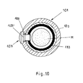
- Fig. 10
- einen Querschnitt durch das Schreibgerät im Bereich eines Schaltelementes.
Claims (26)
- Schreibgerät, das eine Außenhülse (2) aufweist, in deren Innenraum eine Mine (M) axial bewegbar angeordnet ist, die in einer Spitze (4) des Schreibgerätes (1) gelagert ist, oder das eine Kappe (103), ein Griffstück (102) sowie eine Spitze (104) aufweist, die einen Innenraum (101') des Schreibgerätes (101) begrenzen, in dem eine Mine (M) aufgenommen ist, deren Minenspitze (M') in einem Schreibzustand des Schreibgerätes (101) vor dem vorderen Ende (104') der Spitze (104) des Schreibgerätes (101) und in einem Geschlossen-Zustand des Schreibgerätes (101) hinter diesem vorderen Ende (104') der Spitze (104) des Schreibgerätes (101) liegt,
dadurch gekennzeichnet, dass das Schreibgerät (1; 101) ohne Zuhilfenahme oder Abnahme einer eventuell vorhandenen Kappe im Geschlossen-Zustand gegenüber über Länge des Schreibgerätes im Schreibzustand eine kürzere bzw. geringere Länge aufweist. - Schreibgerät nach Anspruch 1,
dadurch gekennzeichnet, dass in der Außenhülse (2) des Schreibgerätes (1) eine die Mine (M) aufnehmende Innenhülse (3) in axialer Richtung des Schreibgerätes (1) bewegbar angeordnet ist, dass die Außenhülse (2) ein Führungselement (8) für ein mit der Innenhülse (3) verbundenes Steuerelement (9) aufweist, und dass durch eine Bewegung des Steuerelementes (9) die Innenhülse (3) von einer ersten Endlage, in der die Minenspitze (M') der Mine (M) hinter dem vorderen Ende (2') der Außenhülse (2) des Schreibgerätes (1) liegt, in eine zweite Endlage, in der die Minenspitze (M') vor dem vorderen Ende (2') der Außenhülse (2) des Schreibgerätes (1) liegt, bewegbar ist, und dass in dieser zweiten Endlage die Innenhülse (3) lagefixierbar ist. - Schreibgerät nach Anspruch 1,
dadurch gekennzeichnet, dass die im Griffstück (2) des Schreibgerätes (1) gelagerte Spitze (4) des Schreibgerätes (1) zwischen zwei Endlagen der Spitze (4) verschiebbar angeordnet ist, wobei in der ersten Endlage der Spitze (4) die Minenspitze (M') der im Schreibgerät (1) aufgenommenen Mine (M) über das vordere Ende (4') der Spitze (4) hervorsteht und in der zweiten Endlage der Spitze (4) die Minenspitze (M') der Mine (M) in axialer Richtung der dem vorderen Ende (4') der Spitze (4) des Schreibgerätes (1) liegt, dass in der Kappe (3) des Schreibgerätes (1) ein Schaltelement (9) angeordnet ist, durch welches die Spitze (4) des Schreibgerätes (1) beaufschlagbar ist, so dass bei einer entsprechenden axialen Bewegung der Kappe (3) zur Spitze (4) hin das Schaltelement (9) die Spitze (4) beaufschlagt und diese von ihrer ersten Endlage in ihre zweite Endlage bewegt, und dass die Kappe (3) des Schreibgerätes (1) in dieser Position der Spitze (4) des Schreibgerätes (1) lagefixierbar ist. - Schreibgerät nach einem der Ansprüche 1 oder 2,
dadurch gekennzeichnet, dass das Schreibgerät (1) eine die Innenhülse (3) beaufschlagende Feder (7) aufweist, durch deren rücktreibende Kraft die Innenhülse (3) von ihrer zweiten in ihre erste Endlage bewegbar ist. - Schreibgerät nach einem der Ansprüche 1, 2 und 4,
dadurch gekennzeichnet, dass die Innenhülse (3) in einer Führungshülse (5) gelagert ist. - Schreibgerät nach Anspruch 5,
dadurch gekennzeichnet, dass die Führungshülse (5) eine erste Anschlagfläche für ein erstes Ende (7a) der Feder (7) ausbildet. - Schreibgerät nach Anspruch 6,
dadurch gekennzeichnet, dass die Innenhülse (3) eine Anschlagfläche für ein zweites Ende (7b) der Feder (7) aufweist. - Schreibgerät nach Anspruch 7,
dadurch gekennzeichnet, dass die zweite Anschlagfläche durch eine Stufe (6) der Innenhülse (3) ausgebildet ist. - Schreibgerät nach einem der Ansprüche 1, 2, 4 bis 8,
dadurch gekennzeichnet, dass das Führungselement (8) einen in axialer Richtung verlaufenden ersten Bereich (8a) und einen quer hierzu verlaufenden zweiten Bereich (8b) aufweist. - Schreibgerät nach einem der Ansprüche 1, 2, 4 bis 9,
dadurch gekennzeichnet, dass das Schaltelement (9) als Schaltstift (9') ausgebildet ist. - Schreibgerät nach einem der Ansprüche 1 oder 3,
dadurch gekennzeichnet, dass im Griffstück (102) des Schreibgerätes (101) eine Führungshülse (110) für die Spitze (104) vorgesehen ist. - Schreibgerät nach einem der Ansprüche 1, 3 und 11,
dadurch gekennzeichnet, dass ein einem vorderen Ende (104') der Spitze (104) zugewandter vorderer Teil (110a) der Führungshülse (110) an einer Innenwand des hülsenförmigen Griffstückes (102) anliegt. - Schreibgerät nach einem der Ansprüche 1, 3, 11 und 12,
dadurch gekennzeichnet, dass der vordere Teil (110a) der Führungshülse (110) fest mit der Innenwand des hülsenförmigen Griffstückes (102) verbunden ist. - Schreibgerät nach einem der Ansprüche 1, 3, 11 bis 13,
dadurch gekennzeichnet, dass die Führungshülse (110) einen rohrförmigen hinteren Teil (110b) aufweist, durch den die Spitze (104) des Schreibgerätes (101) bei ihrer axialen Verschiebebewegung im Schreibgerät (101) führbar ist. - Schreibgerät nach einem der Ansprüche 1, 3, 11 bis 14,
dadurch gekennzeichnet, dass die Führungshülse (110) stufenförmig ausgebildet ist, wobei der vordere Teil (110a) der Führungshülse (110) über eine Stufe (110b) in einen hinteren Teil (110c) der Führungshülse (110) übergeht. - Schreibgerät nach einem der Ansprüche 1, 3, 11 bis 15,
dadurch gekennzeichnet, dass die Stufe (110b) der Führungshülse (110) einen Anschlag für einen vorderen Teil (104a) der Spitze (104) des Schreibgerätes (101) ausbildet, und dass in der ersten Endstellung der Spitze (104) eine Anschlagfläche des gegenüber dem hinteren Teil (104b) der Spitze (104) breiteren vorderen Teils (104a) der Spitze (104) an der Stufe (110b) der Führungshülse (110) anschlägt. - Schreibgerät nach einem der Ansprüche 1, 3, 11 bis 16,
dadurch gekennzeichnet, dass eine Außenwand des rohrförmigen Teils (104b) der Spitze (104) beabstandet zu der Innenwand des Griffstückes (102) angeordnet ist, und dass in diesen durch die Innenwand des Griffstückes (102) und die Außenwand der Führungshülse (110) begrenzten Zwischenraum ein vorderer Bereich (106') eines Kappeninnenrohres (106) der Kappe (103) einschiebbar ist. - Schreibgerät nach einem der Ansprüche 1, 3, 11 bis 17,
dadurch gekennzeichnet, dass koaxial zu dem Kappeninnenrohr (106) des Schreibgerätes (101) eine Steuerhülse (107) angeordnet ist, deren vorderes Ende an der Außenwand des hinteren Teils (110c) der Führungshülse (110) anliegt, und dass das Kappeninnenrohr (106) samt einem fest mit dem Kappeninnenrohr (106) verbundenen Kappenteil (103a) der Kappe (103) in axialer Richtung entlang der Steuerhülse (107) bewegbar ist. - Schreibgerät nach einem der Ansprüche 1, 3, 11 bis 18,
dadurch gekennzeichnet, dass die Steuerhülse (107) ein Führungselement (108) aufweist, in dem ein Schaltelement (109) der Kappe (103) bewegbar ist. - Schreibgerät nach Anspruch 19,
dadurch gekennzeichnet, dass das Führungselement (108) L-förmig ausgebildet ist und einen in axialer Richtung des Schreibgerätes (101) verlaufenden ersten Bereich (108a) und einen quer zu der axialen Richtung verlaufenden zweiten Bereich (108b) aufweist. - Schreibgerät nach einem der Ansprüche 1, 3, 11 bis 20,
dadurch gekennzeichnet, dass das in dem Führungselement (108) bewegbare Schaltelement (109) als ein Schaltstift (109') ausgebildet ist. - Schreibgerät nach einem der Ansprüche 1, 3, 11 bis 21,
dadurch gekennzeichnet, dass das Schreibgerät (101) eine Rückholfeder (112) für die Spitze (104) aufweist. - Schreibgerät nach Anspruch 22,
dadurch gekennzeichnet, dass die Rückholfeder (112) koaxial zum rohrförmigen Teil (104b) der Spitze (104) angeordnet ist. - Schreibgerät nach einem der Ansprüche 1, 3, 11 bis 23,
dadurch gekennzeichnet, dass das Schreibgerät (101) eine Kappenfeder (115) aufweist, durch welche die Kappe (103) aus ihrer Geschlossen-Stellung in ihre Schreibstellung zurückholbar ist. - Schreibgerät nach einem der Ansprüche 1, 3, 11 bis 24,
dadurch gekennzeichnet, dass das Schreibgerät (101) eine Distanzfeder (117) für die Mine (M) aufweist. - Schreibgerät nach einem der Ansprüche 1, 3, 11 bis 25,
dadurch gekennzeichnet, dass der Kappenteil (103a) der Kappe (103) eine Durchtrittsöffnung (118) aufweist, durch die ein Wechselelement (119) zugänglich ist.
Priority Applications (3)
| Application Number | Priority Date | Filing Date | Title |
|---|---|---|---|
| EP04022316A EP1486349A3 (de) | 2002-01-18 | 2002-12-20 | Schreibgerät |
| SI200230171T SI1329338T1 (sl) | 2002-01-18 | 2002-12-20 | Pisalo |
| DK02028563T DK1329338T3 (da) | 2002-01-18 | 2002-12-20 | Skriveredskab |
Applications Claiming Priority (4)
| Application Number | Priority Date | Filing Date | Title |
|---|---|---|---|
| DE20200806U DE20200806U1 (de) | 2002-01-18 | 2002-01-18 | Schreibgerät |
| DE20200808U DE20200808U1 (de) | 2002-01-18 | 2002-01-18 | Schreibgerät |
| DE20200808U | 2002-01-18 | ||
| DE20200806U | 2002-01-18 |
Related Child Applications (1)
| Application Number | Title | Priority Date | Filing Date |
|---|---|---|---|
| EP04022316.6 Division-Into | 2004-09-20 |
Publications (3)
| Publication Number | Publication Date |
|---|---|
| EP1329338A2 true EP1329338A2 (de) | 2003-07-23 |
| EP1329338A3 EP1329338A3 (de) | 2004-01-02 |
| EP1329338B1 EP1329338B1 (de) | 2005-09-21 |
Family
ID=26057359
Family Applications (2)
| Application Number | Title | Priority Date | Filing Date |
|---|---|---|---|
| EP04022316A Withdrawn EP1486349A3 (de) | 2002-01-18 | 2002-12-20 | Schreibgerät |
| EP02028563A Expired - Lifetime EP1329338B1 (de) | 2002-01-18 | 2002-12-20 | Schreibgerät |
Family Applications Before (1)
| Application Number | Title | Priority Date | Filing Date |
|---|---|---|---|
| EP04022316A Withdrawn EP1486349A3 (de) | 2002-01-18 | 2002-12-20 | Schreibgerät |
Country Status (7)
| Country | Link |
|---|---|
| EP (2) | EP1486349A3 (de) |
| AT (1) | ATE304948T1 (de) |
| DE (1) | DE50204317D1 (de) |
| DK (1) | DK1329338T3 (de) |
| ES (1) | ES2247259T3 (de) |
| PT (1) | PT1329338E (de) |
| SI (1) | SI1329338T1 (de) |
Cited By (6)
| Publication number | Priority date | Publication date | Assignee | Title |
|---|---|---|---|---|
| GB2408237A (en) * | 2003-06-16 | 2005-05-25 | Ming-Jen Hsieh | Retractile pen with slotted barrel and clip |
| CN103722945A (zh) * | 2013-12-25 | 2014-04-16 | 宁波江北瑞臣工艺品设计有限公司 | 防止小孩打开的笔 |
| CN110356144A (zh) * | 2019-07-19 | 2019-10-22 | 杭州简弈科技有限公司 | 一种双向摁压伸缩笔 |
| CN112373222A (zh) * | 2020-11-20 | 2021-02-19 | 得力集团有限公司 | 一种笔的防误操作结构及笔 |
| EP4249283A1 (de) * | 2022-03-23 | 2023-09-27 | BIC Violex Single Member S.A. | Schreibgerät und verfahren dafür |
| WO2024239810A1 (zh) * | 2023-05-24 | 2024-11-28 | 孔志刚 | 弹性笔 |
Families Citing this family (3)
| Publication number | Priority date | Publication date | Assignee | Title |
|---|---|---|---|---|
| GB2467775A (en) * | 2009-02-13 | 2010-08-18 | Richard Colin Thomas Allan | Writing instrument |
| CN103722942A (zh) * | 2013-12-25 | 2014-04-16 | 宁波江北瑞臣工艺品设计有限公司 | 防止儿童开启的笔 |
| CN103754018B (zh) * | 2013-12-25 | 2015-10-14 | 宁波江北瑞臣工艺品设计有限公司 | 一种防止儿童打开的安全笔 |
Family Cites Families (10)
| Publication number | Priority date | Publication date | Assignee | Title |
|---|---|---|---|---|
| DE254849C (de) * | ||||
| DE1695433U (de) * | 1954-09-02 | 1955-03-24 | Merz & Krell Schreibwarenfabri | Kugelschreiber mit versenkbarer schreibpatrone. |
| JPS4934201Y1 (de) * | 1970-08-15 | 1974-09-17 | ||
| US4601599A (en) * | 1983-12-27 | 1986-07-22 | Katoh Kinzoku Kogyo Kabushiki Kaisha | Ball-point pen |
| IT209659Z2 (it) * | 1986-04-17 | 1988-10-24 | Martinelli Erasmo | Oggetto scrivente tascabile con corpo retrattile mediante aletta cernierata. |
| DE3841746A1 (de) * | 1988-12-10 | 1990-06-13 | Geha Werke Gmbh | Schreibgeraet |
| US6022161A (en) * | 1998-06-29 | 2000-02-08 | Choi; Man Soo | Variable-length applicator |
| US6273627B1 (en) * | 2000-10-16 | 2001-08-14 | A.T.X. International, Inc. | Expandable writing instrument |
| US6276855B1 (en) * | 2000-11-01 | 2001-08-21 | Ming-Jen Hsien | Retractile pen |
| CN1364700A (zh) * | 2001-01-09 | 2002-08-21 | A.T.X.国际公司 | 伸缩式书写器具 |
-
2002
- 2002-12-20 AT AT02028563T patent/ATE304948T1/de not_active IP Right Cessation
- 2002-12-20 SI SI200230171T patent/SI1329338T1/sl unknown
- 2002-12-20 EP EP04022316A patent/EP1486349A3/de not_active Withdrawn
- 2002-12-20 DK DK02028563T patent/DK1329338T3/da active
- 2002-12-20 DE DE50204317T patent/DE50204317D1/de not_active Expired - Fee Related
- 2002-12-20 PT PT02028563T patent/PT1329338E/pt unknown
- 2002-12-20 EP EP02028563A patent/EP1329338B1/de not_active Expired - Lifetime
- 2002-12-20 ES ES02028563T patent/ES2247259T3/es not_active Expired - Lifetime
Cited By (8)
| Publication number | Priority date | Publication date | Assignee | Title |
|---|---|---|---|---|
| GB2408237A (en) * | 2003-06-16 | 2005-05-25 | Ming-Jen Hsieh | Retractile pen with slotted barrel and clip |
| CN103722945A (zh) * | 2013-12-25 | 2014-04-16 | 宁波江北瑞臣工艺品设计有限公司 | 防止小孩打开的笔 |
| CN110356144A (zh) * | 2019-07-19 | 2019-10-22 | 杭州简弈科技有限公司 | 一种双向摁压伸缩笔 |
| CN112373222A (zh) * | 2020-11-20 | 2021-02-19 | 得力集团有限公司 | 一种笔的防误操作结构及笔 |
| CN112373222B (zh) * | 2020-11-20 | 2024-03-26 | 得力集团有限公司 | 一种笔的防误操作结构及笔 |
| EP4249283A1 (de) * | 2022-03-23 | 2023-09-27 | BIC Violex Single Member S.A. | Schreibgerät und verfahren dafür |
| US11951762B2 (en) | 2022-03-23 | 2024-04-09 | BIC Violex Single Member S.A. | Writing instrument and method thereof |
| WO2024239810A1 (zh) * | 2023-05-24 | 2024-11-28 | 孔志刚 | 弹性笔 |
Also Published As
| Publication number | Publication date |
|---|---|
| SI1329338T1 (sl) | 2005-12-31 |
| DE50204317D1 (de) | 2006-02-02 |
| EP1329338B1 (de) | 2005-09-21 |
| EP1486349A3 (de) | 2004-12-29 |
| ES2247259T3 (es) | 2006-03-01 |
| DK1329338T3 (da) | 2005-10-17 |
| EP1329338A3 (de) | 2004-01-02 |
| EP1486349A2 (de) | 2004-12-15 |
| ATE304948T1 (de) | 2005-10-15 |
| PT1329338E (pt) | 2005-11-30 |
Similar Documents
| Publication | Publication Date | Title |
|---|---|---|
| DE4037791C1 (de) | ||
| DE3125454A1 (de) | Bohrhammer fuer bohr- und schlagbohrbetrieb | |
| EP1745855A2 (de) | Spender zum ggf. zerstäubten Ausbringen eines insbesondere flüssigen Mediums aus einem Behältnis | |
| EP1513653A2 (de) | Futter zur aufnahme von durch drehen um ihre achse verwendbare werkzeuge | |
| EP0310799A1 (de) | Schraubbares Instrument zum Markieren mit einer Mine aus einem weichen Material | |
| DE202006018883U1 (de) | Chirurgischer Obturator | |
| EP1922004A1 (de) | Schraubendreher für knochenschrauben | |
| EP0458170B1 (de) | Spannfutter | |
| EP2130609B1 (de) | Austragvorrichtung für Medien | |
| EP1526422B1 (de) | Versenkbare Drehgriffvorrichtung einer Schalt-oder Stelleinrichtung insbesondere eines Haushaltsgeräts | |
| DE29716002U1 (de) | Druckkugelschreiber mit Sichtfenster und darunter angeordneter Bedruckhülse | |
| EP1329338A2 (de) | Schreibgerät | |
| DE2441904C2 (de) | Einrichtung zum Verbinden eines Griffes mit einem drehrichtungsumkehrbaren Drillspindelwerkzeug, insbesondere Drillschraubendreher | |
| DE19541214C1 (de) | Drehbetätigungseinrichtung | |
| DE10204733A1 (de) | Montagevorrichtung zum Einschieben elastischer O-Ringe in Innennuten von Werkstücken | |
| DE20105767U1 (de) | Tragbare Werkzeugmaschine mit integrierter Bitschublade | |
| WO1994011204A1 (de) | Gerät zum schreiben oder auftragen einer flüssigkeit oder eines feststoffes | |
| DE19950393A1 (de) | Werkzeugaufnahme für einen Bohr- oder Meisselhammer | |
| EP0721068B1 (de) | Gestell aus lösbar verbindbaren Profilstangen | |
| DE19725401C1 (de) | Bohrvorrichtung mit Begrenzung des Bohrweges | |
| DE20200806U1 (de) | Schreibgerät | |
| EP2088943B1 (de) | Chirurgischer obturator | |
| DE19502779C2 (de) | Druckbleistift | |
| WO2022100983A1 (de) | Schlüssellochverdeck | |
| DE8703023U1 (de) | Auftragseinrichtung |
Legal Events
| Date | Code | Title | Description |
|---|---|---|---|
| PUAI | Public reference made under article 153(3) epc to a published international application that has entered the european phase |
Free format text: ORIGINAL CODE: 0009012 |
|
| AK | Designated contracting states |
Designated state(s): AT BE BG CH CY CZ DE DK EE ES FI FR GB GR IE IT LI LU MC NL PT SE SI SK TR |
|
| AX | Request for extension of the european patent |
Extension state: AL LT LV MK RO SI |
|
| PUAL | Search report despatched |
Free format text: ORIGINAL CODE: 0009013 |
|
| AK | Designated contracting states |
Kind code of ref document: A3 Designated state(s): AT BE BG CH CY CZ DE DK EE ES FI FR GB GR IE IT LI LU MC NL PT SE SI SK TR |
|
| AX | Request for extension of the european patent |
Extension state: AL LT LV MK RO SI |
|
| 17P | Request for examination filed |
Effective date: 20031108 |
|
| 17Q | First examination report despatched |
Effective date: 20040401 |
|
| AKX | Designation fees paid |
Designated state(s): AT BE BG CH CY CZ DE DK EE ES FI FR GB GR IE IT LI LU MC NL PT SE SI SK TR |
|
| GRAP | Despatch of communication of intention to grant a patent |
Free format text: ORIGINAL CODE: EPIDOSNIGR1 |
|
| GRAS | Grant fee paid |
Free format text: ORIGINAL CODE: EPIDOSNIGR3 |
|
| GRAA | (expected) grant |
Free format text: ORIGINAL CODE: 0009210 |
|
| AK | Designated contracting states |
Kind code of ref document: B1 Designated state(s): AT BE BG CH CY CZ DE DK EE ES FI FR GB GR IE IT LI LU MC NL PT SE SI SK TR |
|
| PG25 | Lapsed in a contracting state [announced via postgrant information from national office to epo] |
Ref country code: SK Free format text: LAPSE BECAUSE OF FAILURE TO SUBMIT A TRANSLATION OF THE DESCRIPTION OR TO PAY THE FEE WITHIN THE PRESCRIBED TIME-LIMIT Effective date: 20050921 Ref country code: IE Free format text: LAPSE BECAUSE OF FAILURE TO SUBMIT A TRANSLATION OF THE DESCRIPTION OR TO PAY THE FEE WITHIN THE PRESCRIBED TIME-LIMIT Effective date: 20050921 Ref country code: TR Free format text: LAPSE BECAUSE OF FAILURE TO SUBMIT A TRANSLATION OF THE DESCRIPTION OR TO PAY THE FEE WITHIN THE PRESCRIBED TIME-LIMIT Effective date: 20050921 Ref country code: EE Free format text: LAPSE BECAUSE OF FAILURE TO SUBMIT A TRANSLATION OF THE DESCRIPTION OR TO PAY THE FEE WITHIN THE PRESCRIBED TIME-LIMIT Effective date: 20050921 |
|
| REG | Reference to a national code |
Ref country code: GB Ref legal event code: FG4D Free format text: NOT ENGLISH |
|
| REG | Reference to a national code |
Ref country code: CH Ref legal event code: EP |
|
| GBT | Gb: translation of ep patent filed (gb section 77(6)(a)/1977) |
Effective date: 20050921 |
|
| REG | Reference to a national code |
Ref country code: DK Ref legal event code: T3 |
|
| REG | Reference to a national code |
Ref country code: IE Ref legal event code: FG4D Free format text: LANGUAGE OF EP DOCUMENT: GERMAN |
|
| REF | Corresponds to: |
Ref document number: 50204317 Country of ref document: DE Date of ref document: 20051027 Kind code of ref document: P |
|
| REG | Reference to a national code |
Ref country code: GR Ref legal event code: EP Ref document number: 20050402901 Country of ref document: GR |
|
| REG | Reference to a national code |
Ref country code: SE Ref legal event code: TRGR |
|
| PG25 | Lapsed in a contracting state [announced via postgrant information from national office to epo] |
Ref country code: IT Free format text: LAPSE BECAUSE OF NON-PAYMENT OF DUE FEES Effective date: 20051220 Ref country code: AT Free format text: LAPSE BECAUSE OF NON-PAYMENT OF DUE FEES Effective date: 20051220 Ref country code: CY Free format text: LAPSE BECAUSE OF FAILURE TO SUBMIT A TRANSLATION OF THE DESCRIPTION OR TO PAY THE FEE WITHIN THE PRESCRIBED TIME-LIMIT Effective date: 20051220 |
|
| PG25 | Lapsed in a contracting state [announced via postgrant information from national office to epo] |
Ref country code: ES Free format text: LAPSE BECAUSE OF NON-PAYMENT OF DUE FEES Effective date: 20051221 Ref country code: SI Free format text: LAPSE BECAUSE OF NON-PAYMENT OF DUE FEES Effective date: 20051221 Ref country code: SE Free format text: LAPSE BECAUSE OF NON-PAYMENT OF DUE FEES Effective date: 20051221 Ref country code: BG Free format text: LAPSE BECAUSE OF FAILURE TO SUBMIT A TRANSLATION OF THE DESCRIPTION OR TO PAY THE FEE WITHIN THE PRESCRIBED TIME-LIMIT Effective date: 20051221 |
|
| PG25 | Lapsed in a contracting state [announced via postgrant information from national office to epo] |
Ref country code: LU Free format text: LAPSE BECAUSE OF NON-PAYMENT OF DUE FEES Effective date: 20051231 Ref country code: MC Free format text: LAPSE BECAUSE OF NON-PAYMENT OF DUE FEES Effective date: 20051231 Ref country code: BE Free format text: LAPSE BECAUSE OF NON-PAYMENT OF DUE FEES Effective date: 20051231 |
|
| PG25 | Lapsed in a contracting state [announced via postgrant information from national office to epo] |
Ref country code: DK Free format text: LAPSE BECAUSE OF NON-PAYMENT OF DUE FEES Effective date: 20060102 |
|
| REF | Corresponds to: |
Ref document number: 50204317 Country of ref document: DE Date of ref document: 20060202 Kind code of ref document: P |
|
| PGFP | Annual fee paid to national office [announced via postgrant information from national office to epo] |
Ref country code: DE Payment date: 20060221 Year of fee payment: 4 |
|
| REG | Reference to a national code |
Ref country code: ES Ref legal event code: FG2A Ref document number: 2247259 Country of ref document: ES Kind code of ref document: T3 |
|
| ET | Fr: translation filed | ||
| REG | Reference to a national code |
Ref country code: IE Ref legal event code: FD4D |
|
| PLBE | No opposition filed within time limit |
Free format text: ORIGINAL CODE: 0009261 |
|
| STAA | Information on the status of an ep patent application or granted ep patent |
Free format text: STATUS: NO OPPOSITION FILED WITHIN TIME LIMIT |
|
| REG | Reference to a national code |
Ref country code: DK Ref legal event code: EBP |
|
| EUG | Se: european patent has lapsed | ||
| 26N | No opposition filed |
Effective date: 20060622 |
|
| PG25 | Lapsed in a contracting state [announced via postgrant information from national office to epo] |
Ref country code: PT Free format text: LAPSE BECAUSE OF NON-PAYMENT OF DUE FEES Effective date: 20060920 |
|
| REG | Reference to a national code |
Ref country code: SI Ref legal event code: KO00 Effective date: 20060731 |
|
| REG | Reference to a national code |
Ref country code: PT Ref legal event code: MM4A Free format text: LAPSE DUE TO NON-PAYMENT OF FEES Effective date: 20060920 |
|
| PG25 | Lapsed in a contracting state [announced via postgrant information from national office to epo] |
Ref country code: LI Free format text: LAPSE BECAUSE OF NON-PAYMENT OF DUE FEES Effective date: 20061231 Ref country code: CH Free format text: LAPSE BECAUSE OF NON-PAYMENT OF DUE FEES Effective date: 20061231 |
|
| REG | Reference to a national code |
Ref country code: ES Ref legal event code: FD2A Effective date: 20051221 |
|
| PG25 | Lapsed in a contracting state [announced via postgrant information from national office to epo] |
Ref country code: NL Free format text: LAPSE BECAUSE OF NON-PAYMENT OF DUE FEES Effective date: 20070701 |
|
| PG25 | Lapsed in a contracting state [announced via postgrant information from national office to epo] |
Ref country code: DE Free format text: LAPSE BECAUSE OF NON-PAYMENT OF DUE FEES Effective date: 20070703 |
|
| REG | Reference to a national code |
Ref country code: CH Ref legal event code: PL |
|
| GBPC | Gb: european patent ceased through non-payment of renewal fee |
Effective date: 20061220 |
|
| NLV4 | Nl: lapsed or anulled due to non-payment of the annual fee |
Effective date: 20070701 |
|
| PG25 | Lapsed in a contracting state [announced via postgrant information from national office to epo] |
Ref country code: GB Free format text: LAPSE BECAUSE OF NON-PAYMENT OF DUE FEES Effective date: 20061220 |
|
| BERE | Be: lapsed |
Owner name: *HERLITZ PBS A.G. PAPIER- BURO- UND SCHREIBWAREN Effective date: 20051231 |
|
| PG25 | Lapsed in a contracting state [announced via postgrant information from national office to epo] |
Ref country code: CZ Free format text: LAPSE BECAUSE OF NON-PAYMENT OF DUE FEES Effective date: 20051220 |
|
| PG25 | Lapsed in a contracting state [announced via postgrant information from national office to epo] |
Ref country code: PT Free format text: LAPSE BECAUSE OF NON-PAYMENT OF DUE FEES Effective date: 20051220 |
|
| PG25 | Lapsed in a contracting state [announced via postgrant information from national office to epo] |
Ref country code: FR Free format text: LAPSE BECAUSE OF NON-PAYMENT OF DUE FEES Effective date: 20051231 Ref country code: GR Free format text: LAPSE BECAUSE OF NON-PAYMENT OF DUE FEES Effective date: 20070704 |
|
| REG | Reference to a national code |
Ref country code: FR Ref legal event code: ST Effective date: 20111202 |