EP1329338A2 - Writing implement - Google Patents
Writing implement Download PDFInfo
- Publication number
- EP1329338A2 EP1329338A2 EP02028563A EP02028563A EP1329338A2 EP 1329338 A2 EP1329338 A2 EP 1329338A2 EP 02028563 A EP02028563 A EP 02028563A EP 02028563 A EP02028563 A EP 02028563A EP 1329338 A2 EP1329338 A2 EP 1329338A2
- Authority
- EP
- European Patent Office
- Prior art keywords
- writing instrument
- tip
- writing
- sleeve
- cap
- Prior art date
- Legal status (The legal status is an assumption and is not a legal conclusion. Google has not performed a legal analysis and makes no representation as to the accuracy of the status listed.)
- Granted
Links
Images


Classifications
-
- B—PERFORMING OPERATIONS; TRANSPORTING
- B43—WRITING OR DRAWING IMPLEMENTS; BUREAU ACCESSORIES
- B43K—IMPLEMENTS FOR WRITING OR DRAWING
- B43K24/00—Mechanisms for selecting, projecting, retracting or locking writing units
- B43K24/02—Mechanisms for selecting, projecting, retracting or locking writing units for locking a single writing unit in only fully projected or retracted positions
- B43K24/04—Mechanisms for selecting, projecting, retracting or locking writing units for locking a single writing unit in only fully projected or retracted positions operated by means sliding in longitudinally-slotted casings
-
- B—PERFORMING OPERATIONS; TRANSPORTING
- B43—WRITING OR DRAWING IMPLEMENTS; BUREAU ACCESSORIES
- B43K—IMPLEMENTS FOR WRITING OR DRAWING
- B43K24/00—Mechanisms for selecting, projecting, retracting or locking writing units
- B43K24/02—Mechanisms for selecting, projecting, retracting or locking writing units for locking a single writing unit in only fully projected or retracted positions
- B43K24/08—Mechanisms for selecting, projecting, retracting or locking writing units for locking a single writing unit in only fully projected or retracted positions operated by push-buttons
Definitions
- a writing instrument which has an outer sleeve, in the interior of which a Mine is axially movable, which is in a tip of the writing instrument is stored is known.
- a disadvantage of such a writing instrument is that its length in writing is essentially equal to the length is in the closed state.
- the construction of this writing instrument enables namely, it does not adversely affect the length of the Writing instrument of the kind necessary for its ergonomic handling Length in the writing state to a smaller length in the closed state shorten the writing instrument, but what of a variety is increasingly demanded by customers because they want a compact one when closed and therefore easy to insert To have writing utensils.
- a writing instrument which has a cap, a handle and a Has tip that delimit an interior of the writing instrument, in a mine is recorded, the tip of the mine in a writing state of the writing instrument in front of the front end of the tip of the writing instrument and behind in a closed state of the writing instrument the front end of the tip of the writing instrument is known.
- adversely with this writing instrument is also that its length in the writing state is substantially equal to the length in the closed state.
- the construction of the known writing instrument makes it possible in disadvantageous way not the length of the writing instrument before the for its ergonomic handling required length in writing to a smaller length in the closed state of the writing instrument shorten what is increasing from a large number of customers is required because they want a compact in the closed state building and therefore easy to insert writing instrument.
- a writing instrument to further develop such that the writing instrument according to the invention in the closed state has a shorter length than when it is written.
- a writing instrument with an outer sleeve, in the interior of which a lead is axially movable is arranged, which is mounted in a tip of the writing instrument or a writing instrument, which has a cap, a handle and a tip has that limit an interior of the writing instrument, in which a Mine is recorded, the tip of the mine in a writing state of the Writing instrument in front of the front end of the tip of the writing instrument and in a closed state of the writing instrument behind it is located at the front end of the tip of the writing instrument, that the writing instrument can be used without the aid or acceptance of a existing cap in the closed state a shorter or lower Length than in the writing state.
- the writing instrument is designed in such a way that in the outer sleeve of the writing instrument an inner sleeve receiving the refill is arranged to be movable in the axial direction of the writing instrument, that the outer sleeve is a guide element for a connected to the inner sleeve Control element, and that by a movement of the Control the inner sleeve from a first end position in which the mine tip the lead behind the front end of the outer sleeve of the The writing instrument lies in a second end position in which the tip of the mine is in front the front end of the outer sleeve of the writing instrument is movable and that the inner sleeve can be fixed in position in this second end position.
- the measures according to the invention advantageously and Way a writing instrument is formed, which is characterized by that its length when closed is significantly less than its length Length in the writing state of the writing instrument according to the invention.
- a writing instrument is formed, which is characterized by that its length when closed is significantly less than its length Length in the writing state of the writing instrument according to the invention.
- a further embodiment according to the invention according to claim 3 exists in that the writing instrument is designed in such a way that the im Handle of the writing instrument, tip of the writing instrument between two end positions of the tip is slidably arranged, in which the first end position of the tip the lead tip of the recorded in the writing instrument Mine protrudes over the front end of the tip and in the second end position of the tip, the lead tip of the lead in the axial direction behind the front end of the tip of the writing instrument is that in the Cap of the writing instrument, a switching element is arranged through which the tip of the writing instrument can be acted on, so that at a corresponding axial movement of the cap to the tip of the writing instrument hin the switching element acts on the tip and this of their first end position moved to its second end position, and that the cap of the The writing instrument can be fixed in position in this position of the tip of the writing instrument is.
- FIGS. 1 and 2 is a first embodiment of a designated 1 Shown writing instrument, which is shown in FIGS. 1 and 2 in a Outer sleeve 2 and a slidably received in the outer sleeve 2
- Inner sleeve 3 with tip 4 is divided.
- a mine M is included, the mine tip M 'in the Tip 4 is stored.
- the inner sleeve 3 is in the outer sleeve 2 via a Guide sleeve 5 mounted, the rear end 5 'a stop surface for forms a first end 7a of a spring 7.
- a second stop surface for the spring 7 is formed by a circumferential step 3a of the inner sleeve 3.
- the outer sleeve 2 has a guide element 8 for with the inner sleeve 3 connected switching element 9.
- the guide element 8 has one in the axial direction first region 8a and a transverse to it extending second region 8b, in which in the case shown here as Switch pin 9 'formed switching element 9 is movable.
- the inner sleeve 3 In the closed state of the Writing instrument 1, the inner sleeve 3 by the force of the spring 7 in it held second end position in which the mine tip M 'of the mine M behind the front end 2 'of the outer sleeve 2.
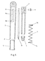
- FIGS. 5 and 6 is a second embodiment of a designated 101 Shown writing instrument, which according to FIGS. 5 and 6 in a handle 102, a cap 103 and a tip 104 is divided.
- the three The aforementioned components delimit an interior 101 'of the writing instrument 101, in which a mine M can be accommodated (FIGS. 8 and 9), the tip of which M 'in the writing state of writing device 101 shown in FIG. 5 protrudes over a front end 104 'of the tip 104 and in the closed state of the writing instrument 101 behind the front end 104 'of the tip 104 of the writing instrument 101 lies and is thus protected in whose interior 101 'is recorded.
- the mine tip M '- as can be seen in FIG. 5 - to move from its writing state to the inside of the tip 104 provided that the cap 103 axially in the direction of the handle 102 is shifted, which causes - as will be explained below -
- the tip 104 advanced in the axial direction of the writing instrument 101 and thus covers the mine tip M 'of the mine M.
- Such The approach does not only have the advantage that this makes it particularly simple way a protected recording of mine M in Interior 101 'of the writing instrument 101 can be achieved, but also that the length of the described in an advantageous manner Writing instrument 101 in its closed state shown in FIG. 2 is significantly shortened so that this then compact writing instrument 101 can be stored easily and in a space-saving manner after - as below also described in detail - the cap 103 in the in Fig. 7th position shown was locked.
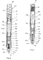
- the tip 104 of the writing instrument 101 is tubular formed and axially displaceable in the handle 102 of the writing instrument 101 stored, at least from their first shown in Fig. 8 End position in its second end position shown in FIG. 9.
- a guide sleeve 110 is provided, a front Front part 110a on the inner wall facing end 104 'of tip 109 of the sleeve-shaped handle 102 rests and is preferably fixed connected to it. This ensures a safe arrangement of the guide sleeve 110a reached in the writing instrument 101.
- the front part 110a of the guide sleeve 110 goes over a step 110b into a rear part 110c, which is the actual guidance of the tubular tip 104 in the handle 102 of the writing instrument 101 is used, by the outer wall of the tubular portion 104b of the tip 104 the inner wall of the rear part 110c of the guide sleeve 110.
- the step 110b forms a stop for a front part 104a of the Tip 104 of the writing instrument 101.
- the step-like configuration of the guide sleeve 110 furthermore causes that the outer wall of the tubular part 104b of the tip 104 spaced from the inner wall of the handle 102, so that in these through the inner wall and the outer wall of the guide sleeve 110 limited space a front portion 6 'of a cap inner tube 106 of the cap 103 can be inserted.
- Control sleeve 107 arranged, the front end 107a on the outer wall of the rear part 110c of the guide sleeve 110 and preferably is firmly connected to this, whereby the control sleeve 107 in Interior 101 'of the writing instrument 101 is fixed in position.
- the control sleeve 107 serves on the one hand as a guide for the inner cap tube 106, so that the inner cap tube 106 and thus that with this inner cap tube 106 firmly connected actual cap part 103a of the cap 103 in its in 6 and 8 shown in its closed position shown in Fig. 7 is movable along the control sleeve 107.
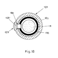
- the control sleeve 107 also has a guide element 108 with a region 108a running in the axial direction for a here as Switch pin 109 'formed switching element 109, which with the Cap 103 is connected and serves to advance the cap 103 towards the handle 102 a rear end 104b 'of the tip 104 to act, causing the tip 104 of its shown in Fig. 8 Writing position in its shown in Fig. 9, opposite the writing position advanced closed position is moved by the guide member 108 in the longitudinal region 8a of the guide element 108 is moved.
- the cap 103 of the writing instrument 101 is locked in this closed position.
- the tip 104 of the writing instrument 101 is acted upon by a return spring 112 which is coaxial to the tubular part 104b of the tip 104 is arranged and causes the tip 104 in the closed state of the writing instrument 101 with a spring force acting in the direction of the cap 103 is applied.
- a return spring 112 which is coaxial to the tubular part 104b of the tip 104 is arranged and causes the tip 104 in the closed state of the writing instrument 101 with a spring force acting in the direction of the cap 103 is applied.
- Stop element 113 is provided, which has a first stop for the return spring 112 for the tip 104.
- a second The stop for the return spring 112 is located on the cap side End of the guide sleeve 110 is formed.
- Such a construction has the advantage that when opening of the writing instrument 101 described, which is easy to accomplish as a result is by the cap 103 against their previously described Direction of rotation is moved, which by this rotary movement Switching element 109 from the transverse region 108b in the in FIG region 108a of the guide element 108 extending in the axial direction is moved and a slight retraction of the cap 103 causes the application of the tip 104 by the switching element applied to it 9, the tip 104 is lifted from that shown in FIG second setting in with the writing state of the writing instrument 101 correlated first end position by the action of the return spring 112 is retrieved, which then leads the mine tip M 'of mine M in is in its read-ready state.
- the cap 103 can then again moved back to their starting position shown in Fig. 8 and through there suitable agents are fixed in position.
- cap spring 115 for moving the cap 103 back in which a cap spring 115 is arranged, which on the cap side End of the control sleeve 107 attaches and a driving force on the Exercises cap 103.
- the cap spring 115 causes that by their driving force, the cap 103 automatically from that shown in FIG. 9 Closed position moved to its writing position shown in Fig. 8 becomes.
- the cap spring 115 thus brings about an advantageous manner automatic opening of the writing instrument 101 described.
- a mine M Spacer spring 117 is provided, which on the one hand on the mine M and on the other hand attaches to a stop surface 117 'of the tip 104. hereby is the mine M in the axial direction against a cap on the Control sleeve 107 attached changing element 119 pressed.
- the spacer 117 advantageously causes the mine M in its defined position is held in the writing instrument 101, regardless of the respective position of the tip 104.
- the rear end of the cap part 103a of the cap 103 has a passage opening 118 through which the Changing element 119 is accessible.
Landscapes
- Pens And Brushes (AREA)
- Mechanical Pencils And Projecting And Retracting Systems Therefor, And Multi-System Writing Instruments (AREA)
Abstract
Das Schreibgerät, das eine Außenhülse (2) aufweist, in deren Innenraum
eine Mine (M) axial bewegbar angeordnet ist, die in einer Spitze (4) des
Schreibgerätes (101) gelagert ist, oder das eine Kappe (103), ein
Griffstück (102) sowie eine Spitze (104) aufweist, die einen Innenraum
(101') des Schreibgerätes (101) begrenzen, in dem eine Mine (M) aufgenommen
ist, deren Minenspitze (M') in einem Schreibzustand des
Schreibgerätes (101) vor dem vorderen Ende (104') der Spitze (104) des
Schreibgerätes (101) und in einem Geschlossen-Zustand des Schreibgerätes
(101) hinter diesem vorderen Ende (104') der Spitze (104) des
Schreibgerätes (101) liegt, ist in der Weise ausgebildet, dass das Schreibgerät
(1) ohne Zuhilfenahme oder Abnahme einer eventuell vorhandenen
Kappe im Geschlossen-Zustand gegenüber der Länge des Schreibgerätes
im Schreibzustand eine kürzere bzw. geringere Länge aufweist.

Description
Ein Schreibgerät, das eine Außenhülse aufweist, in deren Innenraum eine Mine axial bewegbar angeordnet ist, die in einer Spitze des Schreibgerätes gelagert ist, ist bekannt. Nachteilig bei einem derartigen Schreibgerät ist, dass seine Länge im Schreibzustand im wesentlichen gleich der Länge im Geschlossen-Zustand ist. Die Konstruktion dieses Schreibgerätes ermöglicht es nämlich in nachteiliger Art und Weise nicht, die Länge des Schreibgerätes von der für seine ergonomische Handhabung erforderlichen Länge im Schreibzustand auf eine kleinere Länge im Geschlossen-Zustand des Schreibgerätes zu verkürzen, was aber von einer Vielzahl von Kunden in zunehmendem Maße gefordert wird, da diese wünschen, ein im Geschlossen-Zustand kompakt bauendes und daher einfach einzusteckendes Schreibgerät zu haben.A writing instrument which has an outer sleeve, in the interior of which a Mine is axially movable, which is in a tip of the writing instrument is stored is known. A disadvantage of such a writing instrument is that its length in writing is essentially equal to the length is in the closed state. The construction of this writing instrument enables namely, it does not adversely affect the length of the Writing instrument of the kind necessary for its ergonomic handling Length in the writing state to a smaller length in the closed state shorten the writing instrument, but what of a variety is increasingly demanded by customers because they want a compact one when closed and therefore easy to insert To have writing utensils.
Ferner ist ein Schreibgerät, welches eine Kappe, ein Griffstück sowie eine Spitze aufweist, die einen Innenraum des Schreibgerätes begrenzen, in dem eine Mine aufgenommen ist, deren Minenspitze in einem Schreibzustand des Schreibgerätes vor dem vorderen Ende der Spitze des Schreibgerätes und in einem Geschlossen-Zustand des Schreibgerätes hinter dem vorderen Ende der Spitze des Schreibgerätes liegt, bekannt. Nachteilig bei diesem Schreibgerät ist ebenfalls, dass seine Länge im Schreibzustand im wesentlichen gleich der Länge im Geschlossen-Zustand ist. Die Konstruktion des bekannten Schreibgerätes ermöglicht es nämlich in nachteiliger Art und Weise nicht, die Länge des Schreibgerätes vor der für seine ergonomische Handhabung erforderlichen Länge im Schreibzustand auf eine kleinere Länge im Geschlossen-Zustand des Schreibgerätes zu verkürzen, was aber von einer Vielzahl von Kunden in zunehmendem Maße gefordert wird, da diese wünschen, ein im Geschlossen-Zustand kompakt bauendes und daher einfach einzusteckendes Schreibgerät zu haben.Furthermore, a writing instrument, which has a cap, a handle and a Has tip that delimit an interior of the writing instrument, in a mine is recorded, the tip of the mine in a writing state of the writing instrument in front of the front end of the tip of the writing instrument and behind in a closed state of the writing instrument the front end of the tip of the writing instrument is known. adversely with this writing instrument is also that its length in the writing state is substantially equal to the length in the closed state. The construction of the known writing instrument makes it possible in disadvantageous way not the length of the writing instrument before the for its ergonomic handling required length in writing to a smaller length in the closed state of the writing instrument shorten what is increasing from a large number of customers is required because they want a compact in the closed state building and therefore easy to insert writing instrument.
Es ist daher die Aufgabe der vorliegenden Erfindung, ein Schreibgerät derart weiterzubilden, dass das erfindungsgemäße Schreibgerät im Geschlossen-Zustand eine kürzer Länge besitzt als im Schreibzustand desselben.It is therefore the object of the present invention, a writing instrument to further develop such that the writing instrument according to the invention in the closed state has a shorter length than when it is written.
Diese Aufgabe wird erfindungsgemäß dadurch gelöst, dass ein Schreibgerät mit einer Außenhülse, in deren Innenraum eine Mine axial bewegbar angeordnet ist, die in einer Spitze des Schreibgerätes gelagert ist oder einem Schreibgerät, welches eine Kappe, ein Griffstück sowie eine Spitze aufweist, die einen Innenraum des Schreibgerätes begrenzen, in dem eine Mine aufgenommen ist, deren Minenspitze in einem Schreibzustand des Schreibgerätes vor dem vorderen Ende der Spitze des Schreibgerätes und in einem Geschlossen-Zustand des Schreibgerätes hinter diesem vorderen Ende der Spitze des Schreibgerätes liegt, so ausgebildet ist, dass das Schreibgerät ohne Zuhilfenahme oder Abnahme einer eventuell vorhandenen Kappe im Geschlossen-Zustand eine kürzere bzw. geringere Länge als im Schreibzustand aufweist.This object is achieved in that a writing instrument with an outer sleeve, in the interior of which a lead is axially movable is arranged, which is mounted in a tip of the writing instrument or a writing instrument, which has a cap, a handle and a tip has that limit an interior of the writing instrument, in which a Mine is recorded, the tip of the mine in a writing state of the Writing instrument in front of the front end of the tip of the writing instrument and in a closed state of the writing instrument behind it is located at the front end of the tip of the writing instrument, that the writing instrument can be used without the aid or acceptance of a existing cap in the closed state a shorter or lower Length than in the writing state.
Nach einer ersten erfindungsgemäßen Ausführungsform der Erfindung
nach Anspruch 2 ist das Schreibgerät in der Weise ausgebildet, dass in
der Außenhülse des Schreibgerätes eine die Mine aufnehmende Innenhülse
in axialer Richtung des Schreibgerätes bewegbar angeordnet ist,
dass die Außenhülse ein Führungselement für ein mit der Innenhülse verbundenes
Steuerelement aufweist, und dass durch eine Bewegung des
Steuerelementes die Innenhülse von einer ersten Endlage, in der die Minenspitze
der Mine hinter dem vorderen Ende der Außenhülse des
Schreibgerätes liegt, in eine zweite Endlage, in der die Minenspitze vor
dem vorderen Ende der Außenhülse des Schreibgerätes liegt, bewegbar
ist, und dass in dieser zweiten Endlage die Innenhülse lagefixierbar ist. According to a first embodiment of the invention
according to
Durch die erfindungsgemäßen Maßnahmen wird in vorteilhafter Art und Weise ein Schreibgerät ausgebildet, welches sich dadurch auszeichnet, dass seine Länge im Geschlossen-Zustand deutlich geringer als seine Länge im Schreibzustand des erfindungsgemäßen Schreibgerätes ist. Hierdurch wird in vorteilhafter Art und Weise zum einen erreicht, dass im Schreibzustand das Schreibgerät eine hinreichend große Länge besitzt, die eine ergonomische Handhabung des erfindungsgemäßen Schreibgerätes ermöglicht, aber andererseits im Geschlossen-Zustand kompakt baut, so dass sich das erfindungsgemäße Schreibgerät aufgrund seiner geringen Abmessungen einfach einstecken lässt.The measures according to the invention advantageously and Way a writing instrument is formed, which is characterized by that its length when closed is significantly less than its length Length in the writing state of the writing instrument according to the invention. In this way, it is advantageously achieved on the one hand that in Writing condition the writing instrument has a sufficiently long length, an ergonomic handling of the writing instrument according to the invention enabled, but compact on the other hand when closed builds, so that the writing instrument according to the invention due to its small dimensions can simply be plugged in.
Eine weitere erfindungsgemäße Ausgestaltung nach Anspruch 3 besteht
darin, dass das Schreibgerät in der Weise ausgebildet ist, dass die im
Griffstück des Schreibgerätes gelagerte Spitze des Schreibgerätes zwischen
zwei Endlagen der Spitze verschiebbar angeordnet ist, wobei in der
ersten Endlage der Spitze die Minenspitze der im Schreibgerät aufgenommenen
Mine über das vordere Ende der Spitze hervorsteht und in der
zweiten Endlage der Spitze die Minenspitze der Mine in axialer Richtung
hinter dem vorderen Ende der Spitze des Schreibgerätes liegt, dass in der
Kappe des Schreibgerätes ein Schaltelement angeordnet ist, durch welches
die Spitze des Schreibgerätes beaufschlagbar ist, so dass bei einer
entsprechenden axialen Bewegung der Kappe zur Spitze des Schreibgerätes
hin das Schaltelement die Spitze beaufschlagt und diese von ihrer
ersten Endlage in ihre zweite Endlage bewegt, und dass die Kappe des
Schreibgerätes in dieser Position der Spitze des Schreibgerätes lagefixierbar
ist.A further embodiment according to the invention according to
Durch diese erfindungsgemäßen Maßnahmen wird in vorteilhafter Art und Weise ein Schreibgerät ausgebildet, welches sich dadurch auszeichnet, dass seine Länge im Geschlossen-Zustand deutlich geringer als seine Länge im Schreibzustand des erfindungsgemäßen Schreibgerätes ist. These measures according to the invention advantageously and Way a writing instrument is formed, which is characterized by that its length when closed is significantly less than its length Length in the writing state of the writing instrument according to the invention.
Hierdurch wird in vorteilhafter Art und Weise zum einen erreicht, dass im Schreibzustand das Schreibgerät eine hinreichend große Länge besitzt, die eine ergonomische Handhabung des erfindungsgemäßen Schreibgerätes ermöglicht, aber andererseits im Geschlossen-Zustand kompakt baut, so dass sich das erfindungsgemäße Schreibgerät aufgrund seiner geringen Abmessungen einfach einstecken lässt.In this way, it is advantageously achieved on the one hand that in Writing condition the writing instrument has a sufficiently long length, an ergonomic handling of the writing instrument according to the invention enabled, but compact on the other hand when closed builds, so that the writing instrument according to the invention due to its small dimensions can simply be plugged in.
Vorteilhafte Weiterbildungen der Erfindung sind Gegenstand der Unteransprüche.Advantageous developments of the invention are the subject of the dependent claims.
Vorteilhafte Ausgestaltungen des erfindungsgemäßen Schreibgerätes sind in den Zeichnungen dargestellt. Es zeigen:
- Fig. 1
- das Schreibgerät nach einer ersten Ausführungsform,
- Fig. 2
- das Schreibgerät gemäß Fig. 1,
- Fig. 3
- einen Längsschnitt durch das Schreibgerät gemäß Fig. 1,
- Fig. 4
- einen Längsschnitt durch das Schreibgerät gemäß Fig. 2,
- Fig. 5
- eine Funktionsdarstellung der wichtigsten Komponenten des Schreibgerätes im Schnittpunkt,
- Fig.6
- das Schreibgerät nach einer zweiten Ausführungsform in seiner Schreibstellung,
- Fig.7
- das Schreibgerät gemäß Fig. 6 in seiner Geschlossen-Stellung,
- Fig. 8
- einen Längsschnitt durch das Schreibgerät nach Fig. 1,
- Fig. 9
- einen Längsschnitt durch das Schreibgerät gemäß der Fig. 2 und
- Fig. 10
- einen Querschnitt durch das Schreibgerät im Bereich eines Schaltelementes.
- Fig. 1
- the writing instrument according to a first embodiment,
- Fig. 2
- 1,
- Fig. 3
- 2 shows a longitudinal section through the writing instrument according to FIG. 1,
- Fig. 4
- 3 shows a longitudinal section through the writing instrument according to FIG. 2,
- Fig. 5
- a functional representation of the most important components of the writing instrument at the intersection,
- Figure 6
- the writing instrument according to a second embodiment in its writing position,
- Figure 7
- 6 in its closed position,
- Fig. 8
- 2 shows a longitudinal section through the writing instrument according to FIG. 1,
- Fig. 9
- a longitudinal section through the writing instrument according to FIGS. 2 and
- Fig. 10
- a cross section through the writing instrument in the region of a switching element.
In den Fig. 1 bis 5 ist ein erstes Ausführungsbeispiel eines mit 1 bezeichneten
Schreibgerätes dargestellt, welches sich gemäß Fig. 1 und 2 in eine
Außenhülse 2 und eine in der Außenhülse 2 verschiebbar aufgenommene
Innenhülse 3 samt Spitze 4 gliedert. In dem Innenraum 3' (Fig. 3) der Innenhülse
3 ist eine Mine M aufgenommen, deren Minenspitze M' in der
Spitze 4 gelagert ist. Die Innenhülse 3 ist in der Außenhülse 2 über eine
Führungshülse 5 gelagert, deren hinteres Ende 5' eine Anschlagfläche für
ein erstes Ende 7a einer Feder 7 ausbildet. Eine zweite Anschlagfläche für
die Feder 7 wird durch eine umlaufende Stufe 3a der Innenhülse 3 ausgebildet.1 to 5 is a first embodiment of a designated 1
Shown writing instrument, which is shown in FIGS. 1 and 2 in a
Die Außenhülse 2 weist ein Führungselement 8 für ein mit der Innenhülse
3 verbundenes Schaltelement 9 auf. Das Führungselement 8 besitzt einen
in axialer Richtung verlaufenden ersten Bereich 8a und einen quer hierzu
verlaufenden zweiten Bereich 8b, in dem das im hier gezeigten Fall als
Schaltstift 9' ausgebildetes Schaltelement 9 beweglich ist.The
In dem in den Fig. 2 und 4 dargestellten Geschlossen-Zustand des
Schreibgerätes 1 wird die Innenhülse 3 durch die Kraft der Feder 7 in ihrer
zweiten Endstellung gehalten, in dem die Minenspitze M' der Mine M hinter
dem vorderen Ende 2' der Außenhülse 2 liegt.In the closed state of the
Durch eine entsprechende Verschiebung des Schaltelementes 9 in axialer
Richtung wird nun die Innenhülse 3 entgegen der rücktreibenden Kraft der
Feder 7 nach vorne bewegt, so dass im Schreibzustand des Schreibgerätes
1 die Minenspitze M' - wie in den Fig. 1 und 3 gezeigt - vor dem
vorderen Ende 2' der Außenhülse 2 des Schreibgerätes 1 liegt. In dieser
Position befindet sich das Schaltelement 9 vor dem quer verlaufenden Bereich
8a des Führungselementes 8, so dass durch eine quer zur Vorschubrichtung
verlaufende Bewegung des Schaltelementes 9 dieses in
den quer verlaufenden Bereich 8b des Führungselementes 8 eingebracht
werden kann, wodurch die Innenhülse 9 in dieser Schreibposition des
Schreibgerätes 1 arretiert wird. By a corresponding displacement of the
Zum Schließen des Schreibgerätes 1 wird das Schaltelement 9 auf dem
quer verlaufenden Bereich 8b des Führungselementes 8 in dessen längs
verlaufenden Bereich 8a gebracht und losgelassen, wodurch durch die
rücktreibende Kraft der Feder 7 die Innenhülse 3 wiederum in ihrer in den
Fig. 2 und 4 gezeigten zweiten Endlage, in der die Minenspitze M' hinter
dem vorderen Ende 2' der Außenhülse 2 des Schreibgerätes 1 liegt, zurückbewegt
wird.To close the
In den Fig. 6 bis 10 ist ein zweites Ausführungsbeispiel eines mit 101 bezeichneten
Schreibgerätes dargestellt, welches sich gemäß Fig. 5 und 6 in
ein Griffstück 102, eine Kappe 103 und eine Spitze 104 gliedert. Die drei
vorgenannten Bauteile begrenzen einen Innenraum 101' des Schreibgerätes
101, in dem eine Mine M aufnehmbar ist (Fig. 8 und 9), deren Spitze
M' in dem in Fig. 5 gezeigten Schreibzustand des Schreibgerätes 101
über ein vorderes Ende 104' der Spitze 104 hervorragt und die im Geschlossen-Zustand
des Schreibgerätes 101 hinter dem vorderen Ende
104' der Spitze 104 des Schreibgerätes 101 liegt und dadurch geschützt in
dessen Innenraum 101' aufgenommen ist.6 to 10 is a second embodiment of a designated 101
Shown writing instrument, which according to FIGS. 5 and 6 in
a
Um nun die Mine M, deren Minenspitze M' - wie aus Fig. 5 ersichtlich -
aus ihrem Schreibzustand in das Innere der Spitze 104 zu bewegen, ist
vorgesehen, dass die Kappe 103 in Richtung des Griffstückes 102 axial
verschoben wird, was bewirkt, dass - wie weiter unten noch erläutert wird
- die Spitze 104 in axialer Richtung des Schreibgerätes 101 vorgeschoben
wird und derart die Minenspitze M' der Mine M überdeckt. Eine derartige
Vorgangsweise besitzt nicht nur den Vorteil, dass hierdurch in besonders
einfacher Art und Weise eine geschützte Aufnahme der Mine M im
Innenraum 101' des Schreibgerätes 101 erzielbar ist, sondern auch, dass
sich in vorteilhafter Art und Weise die Baulänge des beschriebenen
Schreibgerätes 101 in seinem in Fig. 2 dargestellten Geschlossen-Zustand
wesentlich gekürzt ist, so dass dieses dann kompakte Schreibgerät
101 leicht und platzsparend verwahrbar ist, nachdem - wie weiter unten
ebenfalls noch im Detail beschrieben - die Kappe 103 in der in Fig. 7
gezeigten Stellung arretiert wurde.Around the mine M, the mine tip M '- as can be seen in FIG. 5 -
to move from its writing state to the inside of the
Aus den Fig. 8 bis 10 ist der geometrisch-konstruktive Aufbau des
Schreibgerätes 101 im Längsschnitt dargestellt. Wie aus diesen Figuren
ersichtlich ist, ist die Spitze 104 des Schreibgerätes 101 röhrenförmig
ausgebildet und im Griffstück 102 des Schreibgerätes 101 axial verschiebbar
gelagert, und zwar zumindest von ihrer in Fig. 8 gezeigten ersten
Endlage in ihrer in Fig. 9 gezeigten zweiten Endlage. Um eine einfache
Führung der Spitze 104 im Griffstück 102 des Schreibgerätes 101 zu
erreichen, ist eine Führungshülse 110 vorgesehen, deren einem vorderen
Ende 104' der Spitze 109 zugewandter vorderer Teil 110a an der Innenwand
des hülsenförmigen Griffstückes 102 anliegt und vorzugsweise fest
mit diesem verbunden ist. Hierdurch wird eine sichere Anordnung der Führungshülse
110a im Schreibgerät 101 erreicht.8 to 10 is the geometrical construction of the
Der vordere Teil 110a der Führungshülse 110 geht über eine Stufe 110b
in einen hinteren Teil 110c über, welcher der eigentlichen Führung der
rohrförmigen Spitze 104 im Griffstück 102 des Schreibgerätes 101 dient,
indem die Außenwand des röhrenförmigen Teils 104b der Spitze 104 an
der Innenwand des hinteren Teils 110c der Führungshülse 110 anliegt.
Die Stufe 110b bildet einen Anschlag für einen vorderen Teil 104a der
Spitze 104 des Schreibgerätes 101 aus. Wie aus Fig. 8 ersichtlich ist,
schlägt in der ersten Endstellung der Spitze 104 eine Anschlagfläche
104a' des gegenüber dem hinteren Teil 104b breiteren vorderen Teils
104a der Spitze 104 an der Stufe 110b der Führungshülse 110 an und
verhindert dadurch, dass die Spitze 104 weiter in den Innenraum 101' des
Schreibgerätes 101 einschiebbar ist.The front part 110a of the
Die stufenförmige Ausgestaltung der Führungshülse 110 bewirkt des weiteren,
dass die Außenwand des rohrförmigen Teils 104b der Spitze 104
beabstandet zu der Innenwand des Griffstückes 102 angeordnet ist, so
dass in diesen durch die Innenwand und die Außenwand der Führungshülse
110 begrenzten Zwischenraum ein vorderer Bereich 6' eines Kappeninnenrohrs
106 der Kappe 103 einschiebbar ist.The step-like configuration of the
Koaxial zu dem Kappeninnenrohr 106 des Schreibgerätes 101 ist eine
Steuerhülse 107 angeordnet, deren vorderes Ende 107a an der Außenwand
des hinteren Teils 110c der Führungshülse 110 anliegt und vorzugsweise
fest mit dieser verbunden ist, wodurch die Steuerhülse 107 im
Innenraum 101' des Schreibgerätes 101 lagefixiert wird. Die Steuerhülse
107 dient einerseits als Führung für das Kappeninnenrohr 106, so dass
das Kappeninnenrohr 106 und somit der mit diesem Kappeninnenrohr 106
fest verbundene eigentliche Kappenteil 103a der Kappe 103 in seiner in
den Fig. 6 und 8 gezeigten Schreibstellung in seine in Fig. 7 gezeigte Geschlossen-Stellung
entlang der Steuerhülse 107 bewegbar ist.One is coaxial with the
Des weiteren weist die Steuerhülse 107 noch ein Führungselement 108
mit einem in axialer Richtung verlaufenden Bereich 108a für ein hier als
Schaltstift 109' ausgebildetes Schaltelement 109 auf, welches mit der
Kappe 103 verbunden ist und dazu dient, beim Vorschub der Kappe 103
in Richtung des Griffstückes 102 ein hinteres Ende 104b' der Spitze 104
zu beaufschlagen, wodurch die Spitze 104 von ihrer in Fig. 8 gezeigten
Schreibstellung in ihre in Fig. 9 gezeigte, gegenüber der Schreibstellung
vorgeschobenen Geschlossen-Stellung bewegt wird, indem das Führungselement
108 im längsverlaufenden Bereich 8a des Führungselementes
108 verschoben wird.The
Vorzugsweise ist vorgesehen, dass die Kappe 103 des Schreibgerätes
101 in dieser Geschlossen-Stellung arretiert wird. Dies wird beim gezeigten
Ausführungsbeispiel in besonders einfacher Art und Weise dadurch
erreicht, dass das Führungselement 108 der Steuerhülse 107 L-förmig
ausgebildet ist, so dass durch eine einfache Drehung der Kappe 103 in
ihrer axialen Geschlossen-Stellung das an der Kappe 103 angeordnete
Schaltelement 109 in den quer verlaufenden Bereich 108b des Führungselementes
108 bewegt werden kann, wodurch die Kappe 103 gegen ein
unbeabsichtigtes Zurückschieben gesichert wird.It is preferably provided that the
Vorzugsweise ist vorgesehen, dass die Spitze 104 des Schreibgerätes
101 von einer Rückholfeder 112 beaufschlagt wird, welches koaxial zum
rohrförmigen Teil 104b der Spitze 104 angeordnet ist und bewirkt, dass
die Spitze 104 im Geschlossen-Zustand des Schreibgerätes 101 mit einer
in Richtung der Kappe 103 wirkenden Federkraft beaufschlagt wird. Hierzu
ist vorgesehen, dass im der Kappe 103 zugewandten Bereich des rohrförmigen
Teils 104b der Spitze 104 ein fest mit diesem Teil 104b verbundenes
Anschlagelement 113 vorgesehen ist, welches einen ersten Anschlag
für die Rückholfeder 112 für die Spitze 104 ausbildet. Ein zweiter
Anschlag für die Rückholfeder 112 wird durch das kappenseitig gelegene
Ende der Führungshülse 110 ausgebildet.It is preferably provided that the
Eine derartige Konstruktionsweise besitzt den Vorteil, dass beim Öffnen
des beschriebenen Schreibgerätes 101, welches leicht dadurch zu bewerkstelligen
ist, indem die Kappe 103 entgegen ihrer vorher beschriebenen
Drehrichtung bewegt wird, wobei durch diese Drehbewegung das
Schaltelement 109 aus dem quer verlaufenden Bereich 108b in den in
axialer Richtung verlaufenden Bereich 108a des Führungselementes 108
bewegt wird und ein leichtes Zurückbewegen der Kappe 103 bewirkt, dass
die Beaufschlagung der Spitze 104 durch das auf ihr ansetzende Schaltelement
9 aufgehoben wird, die Spitze 104 von ihrer in Fig. 9 gezeigten
zweiten Einstellung in ihre mit dem Schreibzustand des Schreibgerätes
101 korrelierte erste Endstellung durch die Wirkung der Rückholfeder 112
zurückgeholt wird, wodurch sich dann die Minenspitze M' der Mine M in
ihren schreibbereiten Zustand befindet. Die Kappe 103 kann dann wieder
in ihre in Fig. 8 gezeigte Ausgangsstellung zurückbewegt und dort durch
geeignete Mittel lagefixiert werden. Such a construction has the advantage that when opening
of the
Vorzugsweise ist vorgesehen, dass zur Zurückbewegung der Kappe 103
in der ihr eine Kappenfeder 115 angeordnet ist, welche am kappenseitigen
Ende der Steuerhülse 107 ansetzt und eine rücktreibende Kraft auf die
Kappe 103 ausübt. Wird nun - wie obenstehend beschrieben - die in ihrer
Geschlossen-Stellung befindliche Kappe 103 des Schreibgerätes 101 aus
ihrer Arretierung gelöst, so bewirkt die Kappenfeder 115, dass durch ihre
rücktreibende Kraft die Kappe 103 selbsttätig von ihrer in Fig. 9 gezeigten
Geschlossen-Stellung in ihre in Fig. 8 gezeigte Schreibstellung bewegt
wird. Die Kappenfeder 115 bewirkt somit in vorteilhafter Art und Weise ein
automatisches Öffnen des beschriebenen Schreibgerätes 101.It is preferably provided that for moving the
Wie ebenfalls aus den Fig. 8 und 9 ersichtlich ist, ist vorgesehen, dass in
der Spitze 104 des Schreibgerätes 101 eine die Mine M beaufschlagende
Distanzfeder 117 vorgesehen ist, welche einerseits an der Mine M und
andererseits an einer Anschlagfläche 117' der Spitze 104 ansetzt. Hierdurch
wird die Mine M in axialer Richtung gegen ein kappenseitig an der
Steuerhülse 107 befestigtes Wechselelement 119 gedrückt. Die Distanzfeder
117 bewirkt in vorteilhafter Art und Weise, dass die Mine M in ihrer
definierten Position im Schreibgerät 101 gehalten wird, unabhängig von
der jeweiligen Position der Spitze 104.As can also be seen from FIGS. 8 and 9, it is provided that in
the
Vorzugsweise ist vorgesehen, dass das hintere Ende des Kappenteils
103a der Kappe 103 eine Durchtrittsöffnung 118 aufweist, durch die das
Wechselelement 119 zugänglich ist. Durch ein einfaches Entfernen des
Wechselelementes 119 ist es dann leicht möglich, die Mine M zu wechseln.It is preferably provided that the rear end of the cap part
103a of the
Claims (26)
dadurch gekennzeichnet, dass das Schreibgerät (1; 101) ohne Zuhilfenahme oder Abnahme einer eventuell vorhandenen Kappe im Geschlossen-Zustand gegenüber über Länge des Schreibgerätes im Schreibzustand eine kürzere bzw. geringere Länge aufweist.Writing device which has an outer sleeve (2), in the interior of which a lead (M) is arranged to be axially movable and which is mounted in a tip (4) of the writing device (1), or which has a cap (103), a handle (102 ) and a tip (104) which delimit an interior (101 ') of the writing instrument (101) in which a lead (M) is received, the lead tip (M') of the writing instrument (101) in a writing state in front of the front The end (104 ') of the tip (104) of the writing instrument (101) and in a closed state of the writing instrument (101) behind this front end (104') of the tip (104) of the writing instrument (101),
characterized in that the writing instrument (1; 101) has a shorter or shorter length compared to the length of the writing instrument in the writing state, without the aid or removal of any cap that may be present.
dadurch gekennzeichnet, dass in der Außenhülse (2) des Schreibgerätes (1) eine die Mine (M) aufnehmende Innenhülse (3) in axialer Richtung des Schreibgerätes (1) bewegbar angeordnet ist, dass die Außenhülse (2) ein Führungselement (8) für ein mit der Innenhülse (3) verbundenes Steuerelement (9) aufweist, und dass durch eine Bewegung des Steuerelementes (9) die Innenhülse (3) von einer ersten Endlage, in der die Minenspitze (M') der Mine (M) hinter dem vorderen Ende (2') der Außenhülse (2) des Schreibgerätes (1) liegt, in eine zweite Endlage, in der die Minenspitze (M') vor dem vorderen Ende (2') der Außenhülse (2) des Schreibgerätes (1) liegt, bewegbar ist, und dass in dieser zweiten Endlage die Innenhülse (3) lagefixierbar ist. Writing instrument according to claim 1,
characterized in that in the outer sleeve (2) of the writing instrument (1) an inner sleeve (3) receiving the refill (M) is movably arranged in the axial direction of the writing instrument (1), that the outer sleeve (2) is a guide element (8) for a control element (9) connected to the inner sleeve (3), and that by moving the control element (9) the inner sleeve (3) from a first end position, in which the lead tip (M ') of the lead (M) behind the front The end (2 ') of the outer sleeve (2) of the writing instrument (1) lies in a second end position in which the lead tip (M') lies in front of the front end (2 ') of the outer sleeve (2) of the writing instrument (1). is movable, and that in this second end position, the inner sleeve (3) can be fixed in position.
dadurch gekennzeichnet, dass die im Griffstück (2) des Schreibgerätes (1) gelagerte Spitze (4) des Schreibgerätes (1) zwischen zwei Endlagen der Spitze (4) verschiebbar angeordnet ist, wobei in der ersten Endlage der Spitze (4) die Minenspitze (M') der im Schreibgerät (1) aufgenommenen Mine (M) über das vordere Ende (4') der Spitze (4) hervorsteht und in der zweiten Endlage der Spitze (4) die Minenspitze (M') der Mine (M) in axialer Richtung der dem vorderen Ende (4') der Spitze (4) des Schreibgerätes (1) liegt, dass in der Kappe (3) des Schreibgerätes (1) ein Schaltelement (9) angeordnet ist, durch welches die Spitze (4) des Schreibgerätes (1) beaufschlagbar ist, so dass bei einer entsprechenden axialen Bewegung der Kappe (3) zur Spitze (4) hin das Schaltelement (9) die Spitze (4) beaufschlagt und diese von ihrer ersten Endlage in ihre zweite Endlage bewegt, und dass die Kappe (3) des Schreibgerätes (1) in dieser Position der Spitze (4) des Schreibgerätes (1) lagefixierbar ist.Writing instrument according to claim 1,
characterized in that the tip (4) of the writing instrument (1) mounted in the handle (2) of the writing instrument (1) is displaceably arranged between two end positions of the tip (4), the lead tip (4) in the first end position of the tip (4) M ') of the lead (M) received in the writing instrument (1) protrudes over the front end (4') of the tip (4) and in the second end position of the tip (4) the lead tip (M ') of the lead (M) in Axial direction of the front end (4 ') of the tip (4) of the writing instrument (1) is that a switching element (9) is arranged in the cap (3) of the writing instrument (1), through which the tip (4) of the Writing device (1) can be acted upon, so that when the cap (3) moves axially towards the tip (4), the switching element (9) acts on the tip (4) and moves it from its first end position to its second end position, and that the cap (3) of the writing instrument (1) in this position of the tip (4) of the writing instrument (1) fixable i st.
dadurch gekennzeichnet, dass das Schreibgerät (1) eine die Innenhülse (3) beaufschlagende Feder (7) aufweist, durch deren rücktreibende Kraft die Innenhülse (3) von ihrer zweiten in ihre erste Endlage bewegbar ist.Writing implement according to one of claims 1 or 2,
characterized in that the writing instrument (1) has a spring (7) acting on the inner sleeve (3), the restoring force of which allows the inner sleeve (3) to be moved from its second to its first end position.
dadurch gekennzeichnet, dass die Innenhülse (3) in einer Führungshülse (5) gelagert ist.Writing implement according to one of claims 1, 2 and 4,
characterized in that the inner sleeve (3) is mounted in a guide sleeve (5).
dadurch gekennzeichnet, dass die Führungshülse (5) eine erste Anschlagfläche für ein erstes Ende (7a) der Feder (7) ausbildet. Writing instrument according to claim 5,
characterized in that the guide sleeve (5) forms a first stop surface for a first end (7a) of the spring (7).
dadurch gekennzeichnet, dass die Innenhülse (3) eine Anschlagfläche für ein zweites Ende (7b) der Feder (7) aufweist.Writing instrument according to claim 6,
characterized in that the inner sleeve (3) has a stop surface for a second end (7b) of the spring (7).
dadurch gekennzeichnet, dass die zweite Anschlagfläche durch eine Stufe (6) der Innenhülse (3) ausgebildet ist.Writing instrument according to claim 7,
characterized in that the second stop surface is formed by a step (6) of the inner sleeve (3).
dadurch gekennzeichnet, dass das Führungselement (8) einen in axialer Richtung verlaufenden ersten Bereich (8a) und einen quer hierzu verlaufenden zweiten Bereich (8b) aufweist.Writing instrument according to one of claims 1, 2, 4 to 8,
characterized in that the guide element (8) has a first region (8a) running in the axial direction and a second region (8b) running transversely thereto.
dadurch gekennzeichnet, dass das Schaltelement (9) als Schaltstift (9') ausgebildet ist.Writing instrument according to one of claims 1, 2, 4 to 9,
characterized in that the switching element (9) is designed as a switching pin (9 ').
dadurch gekennzeichnet, dass im Griffstück (102) des Schreibgerätes (101) eine Führungshülse (110) für die Spitze (104) vorgesehen ist.Writing implement according to one of claims 1 or 3,
characterized in that a guide sleeve (110) for the tip (104) is provided in the handle (102) of the writing instrument (101).
dadurch gekennzeichnet, dass ein einem vorderen Ende (104') der Spitze (104) zugewandter vorderer Teil (110a) der Führungshülse (110) an einer Innenwand des hülsenförmigen Griffstückes (102) anliegt. Writing implement according to one of claims 1, 3 and 11,
characterized in that a front part (110a) of the guide sleeve (110) facing a front end (104 ') of the tip (104) bears against an inner wall of the sleeve-shaped handle (102).
dadurch gekennzeichnet, dass der vordere Teil (110a) der Führungshülse (110) fest mit der Innenwand des hülsenförmigen Griffstückes (102) verbunden ist.Writing implement according to one of claims 1, 3, 11 and 12,
characterized in that the front part (110a) of the guide sleeve (110) is fixedly connected to the inner wall of the sleeve-shaped handle (102).
dadurch gekennzeichnet, dass die Führungshülse (110) einen rohrförmigen hinteren Teil (110b) aufweist, durch den die Spitze (104) des Schreibgerätes (101) bei ihrer axialen Verschiebebewegung im Schreibgerät (101) führbar ist.Writing implement according to one of claims 1, 3, 11 to 13,
characterized in that the guide sleeve (110) has a tubular rear part (110b) through which the tip (104) of the writing instrument (101) can be guided in the writing instrument (101) during its axial displacement movement.
dadurch gekennzeichnet, dass die Führungshülse (110) stufenförmig ausgebildet ist, wobei der vordere Teil (110a) der Führungshülse (110) über eine Stufe (110b) in einen hinteren Teil (110c) der Führungshülse (110) übergeht.Writing instrument according to one of claims 1, 3, 11 to 14,
characterized in that the guide sleeve (110) is step-shaped, the front part (110a) of the guide sleeve (110) merging via a step (110b) into a rear part (110c) of the guide sleeve (110).
dadurch gekennzeichnet, dass die Stufe (110b) der Führungshülse (110) einen Anschlag für einen vorderen Teil (104a) der Spitze (104) des Schreibgerätes (101) ausbildet, und dass in der ersten Endstellung der Spitze (104) eine Anschlagfläche des gegenüber dem hinteren Teil (104b) der Spitze (104) breiteren vorderen Teils (104a) der Spitze (104) an der Stufe (110b) der Führungshülse (110) anschlägt.Writing implement according to one of claims 1, 3, 11 to 15,
characterized in that the step (110b) of the guide sleeve (110) forms a stop for a front part (104a) of the tip (104) of the writing instrument (101), and that in the first end position of the tip (104) a stop face of the opposite the rear part (104b) of the tip (104) wider front part (104a) of the tip (104) on the step (110b) of the guide sleeve (110).
dadurch gekennzeichnet, dass eine Außenwand des rohrförmigen Teils (104b) der Spitze (104) beabstandet zu der Innenwand des Griffstückes (102) angeordnet ist, und dass in diesen durch die Innenwand des Griffstückes (102) und die Außenwand der Führungshülse (110) begrenzten Zwischenraum ein vorderer Bereich (106') eines Kappeninnenrohres (106) der Kappe (103) einschiebbar ist.Writing implement according to one of claims 1, 3, 11 to 16,
characterized in that an outer wall of the tubular part (104b) of the tip (104) is arranged at a distance from the inner wall of the handle (102), and in that it is delimited by the inner wall of the handle (102) and the outer wall of the guide sleeve (110) A front area (106 ') of a cap inner tube (106) of the cap (103) can be pushed in between.
dadurch gekennzeichnet, dass koaxial zu dem Kappeninnenrohr (106) des Schreibgerätes (101) eine Steuerhülse (107) angeordnet ist, deren vorderes Ende an der Außenwand des hinteren Teils (110c) der Führungshülse (110) anliegt, und dass das Kappeninnenrohr (106) samt einem fest mit dem Kappeninnenrohr (106) verbundenen Kappenteil (103a) der Kappe (103) in axialer Richtung entlang der Steuerhülse (107) bewegbar ist.Writing implement according to one of claims 1, 3, 11 to 17,
characterized in that a control sleeve (107) is arranged coaxially to the inner cap tube (106) of the writing instrument (101), the front end of which rests on the outer wall of the rear part (110c) of the guide sleeve (110), and in that the inner cap tube (106) together with a cap part (103a) of the cap (103) which is fixedly connected to the inner cap tube (106), can be moved in the axial direction along the control sleeve (107).
dadurch gekennzeichnet, dass die Steuerhülse (107) ein Führungselement (108) aufweist, in dem ein Schaltelement (109) der Kappe (103) bewegbar ist.Writing implement according to one of claims 1, 3, 11 to 18,
characterized in that the control sleeve (107) has a guide element (108) in which a switching element (109) of the cap (103) can be moved.
dadurch gekennzeichnet, dass das Führungselement (108) L-förmig ausgebildet ist und einen in axialer Richtung des Schreibgerätes (101) verlaufenden ersten Bereich (108a) und einen quer zu der axialen Richtung verlaufenden zweiten Bereich (108b) aufweist.Writing instrument according to claim 19,
characterized in that the guide element (108) is L-shaped and has a first region (108a) running in the axial direction of the writing instrument (101) and a second region (108b) running transversely to the axial direction.
dadurch gekennzeichnet, dass das in dem Führungselement (108) bewegbare Schaltelement (109) als ein Schaltstift (109') ausgebildet ist. Writing implement according to one of claims 1, 3, 11 to 20,
characterized in that the switching element (109) movable in the guide element (108) is designed as a switching pin (109 ').
dadurch gekennzeichnet, dass das Schreibgerät (101) eine Rückholfeder (112) für die Spitze (104) aufweist.Writing implement according to one of claims 1, 3, 11 to 21,
characterized in that the writing instrument (101) has a return spring (112) for the tip (104).
dadurch gekennzeichnet, dass die Rückholfeder (112) koaxial zum rohrförmigen Teil (104b) der Spitze (104) angeordnet ist.Writing instrument according to claim 22,
characterized in that the return spring (112) is arranged coaxially with the tubular part (104b) of the tip (104).
dadurch gekennzeichnet, dass das Schreibgerät (101) eine Kappenfeder (115) aufweist, durch welche die Kappe (103) aus ihrer Geschlossen-Stellung in ihre Schreibstellung zurückholbar ist.Writing implement according to one of claims 1, 3, 11 to 23,
characterized in that the writing instrument (101) has a cap spring (115) through which the cap (103) can be returned from its closed position to its writing position.
dadurch gekennzeichnet, dass das Schreibgerät (101) eine Distanzfeder (117) für die Mine (M) aufweist.Writing instrument according to one of claims 1, 3, 11 to 24,
characterized in that the writing instrument (101) has a spacer spring (117) for the lead (M).
dadurch gekennzeichnet, dass der Kappenteil (103a) der Kappe (103) eine Durchtrittsöffnung (118) aufweist, durch die ein Wechselelement (119) zugänglich ist.Writing implement according to one of claims 1, 3, 11 to 25,
characterized in that the cap part (103a) of the cap (103) has a passage opening (118) through which an interchangeable element (119) is accessible.
Priority Applications (3)
| Application Number | Priority Date | Filing Date | Title |
|---|---|---|---|
| EP04022316A EP1486349A3 (en) | 2002-01-18 | 2002-12-20 | Writing implement |
| SI200230171T SI1329338T1 (en) | 2002-01-18 | 2002-12-20 | Writing implement |
| DK02028563T DK1329338T3 (en) | 2002-01-18 | 2002-12-20 | writing implement |
Applications Claiming Priority (4)
| Application Number | Priority Date | Filing Date | Title |
|---|---|---|---|
| DE20200806U DE20200806U1 (en) | 2002-01-18 | 2002-01-18 | writing implement |
| DE20200806U | 2002-01-18 | ||
| DE20200808U | 2002-01-18 | ||
| DE20200808U DE20200808U1 (en) | 2002-01-18 | 2002-01-18 | writing implement |
Related Child Applications (1)
| Application Number | Title | Priority Date | Filing Date |
|---|---|---|---|
| EP04022316.6 Division-Into | 2004-09-20 |
Publications (3)
| Publication Number | Publication Date |
|---|---|
| EP1329338A2 true EP1329338A2 (en) | 2003-07-23 |
| EP1329338A3 EP1329338A3 (en) | 2004-01-02 |
| EP1329338B1 EP1329338B1 (en) | 2005-09-21 |
Family
ID=26057359
Family Applications (2)
| Application Number | Title | Priority Date | Filing Date |
|---|---|---|---|
| EP04022316A Withdrawn EP1486349A3 (en) | 2002-01-18 | 2002-12-20 | Writing implement |
| EP02028563A Expired - Lifetime EP1329338B1 (en) | 2002-01-18 | 2002-12-20 | Writing implement |
Family Applications Before (1)
| Application Number | Title | Priority Date | Filing Date |
|---|---|---|---|
| EP04022316A Withdrawn EP1486349A3 (en) | 2002-01-18 | 2002-12-20 | Writing implement |
Country Status (7)
| Country | Link |
|---|---|
| EP (2) | EP1486349A3 (en) |
| AT (1) | ATE304948T1 (en) |
| DE (1) | DE50204317D1 (en) |
| DK (1) | DK1329338T3 (en) |
| ES (1) | ES2247259T3 (en) |
| PT (1) | PT1329338E (en) |
| SI (1) | SI1329338T1 (en) |
Cited By (6)
| Publication number | Priority date | Publication date | Assignee | Title |
|---|---|---|---|---|
| GB2408237A (en) * | 2003-06-16 | 2005-05-25 | Ming-Jen Hsieh | Retractile pen with slotted barrel and clip |
| CN103722945A (en) * | 2013-12-25 | 2014-04-16 | 宁波江北瑞臣工艺品设计有限公司 | Pen prevented from being opened by child |
| CN110356144A (en) * | 2019-07-19 | 2019-10-22 | 杭州简弈科技有限公司 | A two-way push-and-press retractable pen |
| CN112373222A (en) * | 2020-11-20 | 2021-02-19 | 得力集团有限公司 | Anti-misoperation structure of pen and pen |
| EP4249283A1 (en) * | 2022-03-23 | 2023-09-27 | BIC Violex Single Member S.A. | A writing instrument and method thereof |
| WO2024239810A1 (en) * | 2023-05-24 | 2024-11-28 | 孔志刚 | Elastic pen |
Families Citing this family (3)
| Publication number | Priority date | Publication date | Assignee | Title |
|---|---|---|---|---|
| GB2467775A (en) * | 2009-02-13 | 2010-08-18 | Richard Colin Thomas Allan | Writing instrument |
| CN103754018B (en) * | 2013-12-25 | 2015-10-14 | 宁波江北瑞臣工艺品设计有限公司 | The safety pen that a kind of children of preventing open |
| CN103722942A (en) * | 2013-12-25 | 2014-04-16 | 宁波江北瑞臣工艺品设计有限公司 | Pen prevented from being opened by child |
Family Cites Families (10)
| Publication number | Priority date | Publication date | Assignee | Title |
|---|---|---|---|---|
| DE254849C (en) * | ||||
| DE1695433U (en) * | 1954-09-02 | 1955-03-24 | Merz & Krell Schreibwarenfabri | BALLPOINT PEN WITH RETRACTABLE CARTRIDGE. |
| JPS4934201Y1 (en) * | 1970-08-15 | 1974-09-17 | ||
| US4601599A (en) * | 1983-12-27 | 1986-07-22 | Katoh Kinzoku Kogyo Kabushiki Kaisha | Ball-point pen |
| IT209659Z2 (en) * | 1986-04-17 | 1988-10-24 | Martinelli Erasmo | POCKET WRITING OBJECT WITH RETRACTABLE BODY BY HINGED FLAP. |
| DE3841746A1 (en) * | 1988-12-10 | 1990-06-13 | Geha Werke Gmbh | Writing device |
| US6022161A (en) * | 1998-06-29 | 2000-02-08 | Choi; Man Soo | Variable-length applicator |
| US6273627B1 (en) * | 2000-10-16 | 2001-08-14 | A.T.X. International, Inc. | Expandable writing instrument |
| US6276855B1 (en) * | 2000-11-01 | 2001-08-21 | Ming-Jen Hsien | Retractile pen |
| CN1364700A (en) * | 2001-01-09 | 2002-08-21 | A.T.X.国际公司 | Telescopic writing tool |
-
2002
- 2002-12-20 DE DE50204317T patent/DE50204317D1/en not_active Expired - Fee Related
- 2002-12-20 ES ES02028563T patent/ES2247259T3/en not_active Expired - Lifetime
- 2002-12-20 DK DK02028563T patent/DK1329338T3/en active
- 2002-12-20 SI SI200230171T patent/SI1329338T1/en unknown
- 2002-12-20 EP EP04022316A patent/EP1486349A3/en not_active Withdrawn
- 2002-12-20 PT PT02028563T patent/PT1329338E/en unknown
- 2002-12-20 EP EP02028563A patent/EP1329338B1/en not_active Expired - Lifetime
- 2002-12-20 AT AT02028563T patent/ATE304948T1/en not_active IP Right Cessation
Cited By (8)
| Publication number | Priority date | Publication date | Assignee | Title |
|---|---|---|---|---|
| GB2408237A (en) * | 2003-06-16 | 2005-05-25 | Ming-Jen Hsieh | Retractile pen with slotted barrel and clip |
| CN103722945A (en) * | 2013-12-25 | 2014-04-16 | 宁波江北瑞臣工艺品设计有限公司 | Pen prevented from being opened by child |
| CN110356144A (en) * | 2019-07-19 | 2019-10-22 | 杭州简弈科技有限公司 | A two-way push-and-press retractable pen |
| CN112373222A (en) * | 2020-11-20 | 2021-02-19 | 得力集团有限公司 | Anti-misoperation structure of pen and pen |
| CN112373222B (en) * | 2020-11-20 | 2024-03-26 | 得力集团有限公司 | Anti-misoperation structure of pen and pen |
| EP4249283A1 (en) * | 2022-03-23 | 2023-09-27 | BIC Violex Single Member S.A. | A writing instrument and method thereof |
| US11951762B2 (en) | 2022-03-23 | 2024-04-09 | BIC Violex Single Member S.A. | Writing instrument and method thereof |
| WO2024239810A1 (en) * | 2023-05-24 | 2024-11-28 | 孔志刚 | Elastic pen |
Also Published As
| Publication number | Publication date |
|---|---|
| ATE304948T1 (en) | 2005-10-15 |
| PT1329338E (en) | 2005-11-30 |
| SI1329338T1 (en) | 2005-12-31 |
| EP1329338A3 (en) | 2004-01-02 |
| DK1329338T3 (en) | 2005-10-17 |
| EP1329338B1 (en) | 2005-09-21 |
| ES2247259T3 (en) | 2006-03-01 |
| EP1486349A2 (en) | 2004-12-15 |
| DE50204317D1 (en) | 2006-02-02 |
| EP1486349A3 (en) | 2004-12-29 |
Similar Documents
| Publication | Publication Date | Title |
|---|---|---|
| EP0487926B1 (en) | Motor driven tool | |
| DE3125454A1 (en) | DRILLING HAMMER FOR DRILLING AND IMPACT DRILLING | |
| EP1745855A2 (en) | Dispenser for dispensing, in particular spraying, a fluid from a container | |
| EP0310799A1 (en) | Propelling instrument for marking with a soft material lead | |
| DE202006018883U1 (en) | Surgical obturator, comprises control element securing the cutting device in an active position | |
| WO2007031132A1 (en) | Screwdriver for bone screws | |
| EP0458170B1 (en) | Chuck | |
| EP2130609B1 (en) | Discharge device for media | |
| EP1526422B1 (en) | Retractable rotating knob of a switch or positioning device, especially of a household appliance | |
| DE29716002U1 (en) | Retractable ballpoint pen with viewing window and printing sleeve arranged underneath | |
| EP1329338A2 (en) | Writing implement | |
| EP1746244A2 (en) | Closure device for openings in buildings | |
| DE2441904C2 (en) | Device for connecting a handle to a reversible drill spindle tool, in particular a drill screwdriver | |
| DE19939734A1 (en) | Security lock cylinder of tumblered core bevels non-keyed end of control pin for work with counter-beveled finalizing tumbler pin. | |
| DE19541214C1 (en) | Rotary actuator | |
| DE20105767U1 (en) | Portable machine tool with integrated bit drawer | |
| WO1994011204A1 (en) | Device for writing or applying a liquid or a solid | |
| EP0118910B1 (en) | Locking cylinder | |
| DE19950393A1 (en) | Tool receiver for hammer drill or hammer chisel, with lock bolt in form of shaped body with recess between projections | |
| EP0721068B1 (en) | Frame consisting of detachable profiles | |
| DE19725401C1 (en) | Drilling device with drilling depth limitation | |
| DE20200806U1 (en) | writing implement | |
| EP2088943B1 (en) | Surgical obturator | |
| DE19502779C2 (en) | Mechanical pencil | |
| WO2022100983A1 (en) | Keyhole cover |
Legal Events
| Date | Code | Title | Description |
|---|---|---|---|
| PUAI | Public reference made under article 153(3) epc to a published international application that has entered the european phase |
Free format text: ORIGINAL CODE: 0009012 |
|
| AK | Designated contracting states |
Designated state(s): AT BE BG CH CY CZ DE DK EE ES FI FR GB GR IE IT LI LU MC NL PT SE SI SK TR |
|
| AX | Request for extension of the european patent |
Extension state: AL LT LV MK RO SI |
|
| PUAL | Search report despatched |
Free format text: ORIGINAL CODE: 0009013 |
|
| AK | Designated contracting states |
Kind code of ref document: A3 Designated state(s): AT BE BG CH CY CZ DE DK EE ES FI FR GB GR IE IT LI LU MC NL PT SE SI SK TR |
|
| AX | Request for extension of the european patent |
Extension state: AL LT LV MK RO SI |
|
| 17P | Request for examination filed |
Effective date: 20031108 |
|
| 17Q | First examination report despatched |
Effective date: 20040401 |
|
| AKX | Designation fees paid |
Designated state(s): AT BE BG CH CY CZ DE DK EE ES FI FR GB GR IE IT LI LU MC NL PT SE SI SK TR |
|
| GRAP | Despatch of communication of intention to grant a patent |
Free format text: ORIGINAL CODE: EPIDOSNIGR1 |
|
| GRAS | Grant fee paid |
Free format text: ORIGINAL CODE: EPIDOSNIGR3 |
|
| GRAA | (expected) grant |
Free format text: ORIGINAL CODE: 0009210 |
|
| AK | Designated contracting states |
Kind code of ref document: B1 Designated state(s): AT BE BG CH CY CZ DE DK EE ES FI FR GB GR IE IT LI LU MC NL PT SE SI SK TR |
|
| PG25 | Lapsed in a contracting state [announced via postgrant information from national office to epo] |
Ref country code: SK Free format text: LAPSE BECAUSE OF FAILURE TO SUBMIT A TRANSLATION OF THE DESCRIPTION OR TO PAY THE FEE WITHIN THE PRESCRIBED TIME-LIMIT Effective date: 20050921 Ref country code: IE Free format text: LAPSE BECAUSE OF FAILURE TO SUBMIT A TRANSLATION OF THE DESCRIPTION OR TO PAY THE FEE WITHIN THE PRESCRIBED TIME-LIMIT Effective date: 20050921 Ref country code: TR Free format text: LAPSE BECAUSE OF FAILURE TO SUBMIT A TRANSLATION OF THE DESCRIPTION OR TO PAY THE FEE WITHIN THE PRESCRIBED TIME-LIMIT Effective date: 20050921 Ref country code: EE Free format text: LAPSE BECAUSE OF FAILURE TO SUBMIT A TRANSLATION OF THE DESCRIPTION OR TO PAY THE FEE WITHIN THE PRESCRIBED TIME-LIMIT Effective date: 20050921 |
|
| REG | Reference to a national code |
Ref country code: GB Ref legal event code: FG4D Free format text: NOT ENGLISH |
|
| REG | Reference to a national code |
Ref country code: CH Ref legal event code: EP |
|
| GBT | Gb: translation of ep patent filed (gb section 77(6)(a)/1977) |
Effective date: 20050921 |
|
| REG | Reference to a national code |
Ref country code: DK Ref legal event code: T3 |
|
| REG | Reference to a national code |
Ref country code: IE Ref legal event code: FG4D Free format text: LANGUAGE OF EP DOCUMENT: GERMAN |
|
| REF | Corresponds to: |
Ref document number: 50204317 Country of ref document: DE Date of ref document: 20051027 Kind code of ref document: P |
|
| REG | Reference to a national code |
Ref country code: GR Ref legal event code: EP Ref document number: 20050402901 Country of ref document: GR |
|
| REG | Reference to a national code |
Ref country code: SE Ref legal event code: TRGR |
|
| PG25 | Lapsed in a contracting state [announced via postgrant information from national office to epo] |
Ref country code: IT Free format text: LAPSE BECAUSE OF NON-PAYMENT OF DUE FEES Effective date: 20051220 Ref country code: AT Free format text: LAPSE BECAUSE OF NON-PAYMENT OF DUE FEES Effective date: 20051220 Ref country code: CY Free format text: LAPSE BECAUSE OF FAILURE TO SUBMIT A TRANSLATION OF THE DESCRIPTION OR TO PAY THE FEE WITHIN THE PRESCRIBED TIME-LIMIT Effective date: 20051220 |
|
| PG25 | Lapsed in a contracting state [announced via postgrant information from national office to epo] |
Ref country code: ES Free format text: LAPSE BECAUSE OF NON-PAYMENT OF DUE FEES Effective date: 20051221 Ref country code: SI Free format text: LAPSE BECAUSE OF NON-PAYMENT OF DUE FEES Effective date: 20051221 Ref country code: SE Free format text: LAPSE BECAUSE OF NON-PAYMENT OF DUE FEES Effective date: 20051221 Ref country code: BG Free format text: LAPSE BECAUSE OF FAILURE TO SUBMIT A TRANSLATION OF THE DESCRIPTION OR TO PAY THE FEE WITHIN THE PRESCRIBED TIME-LIMIT Effective date: 20051221 |
|
| PG25 | Lapsed in a contracting state [announced via postgrant information from national office to epo] |
Ref country code: LU Free format text: LAPSE BECAUSE OF NON-PAYMENT OF DUE FEES Effective date: 20051231 Ref country code: MC Free format text: LAPSE BECAUSE OF NON-PAYMENT OF DUE FEES Effective date: 20051231 Ref country code: BE Free format text: LAPSE BECAUSE OF NON-PAYMENT OF DUE FEES Effective date: 20051231 |
|
| PG25 | Lapsed in a contracting state [announced via postgrant information from national office to epo] |
Ref country code: DK Free format text: LAPSE BECAUSE OF NON-PAYMENT OF DUE FEES Effective date: 20060102 |
|
| REF | Corresponds to: |
Ref document number: 50204317 Country of ref document: DE Date of ref document: 20060202 Kind code of ref document: P |
|
| PGFP | Annual fee paid to national office [announced via postgrant information from national office to epo] |
Ref country code: DE Payment date: 20060221 Year of fee payment: 4 |
|
| REG | Reference to a national code |
Ref country code: ES Ref legal event code: FG2A Ref document number: 2247259 Country of ref document: ES Kind code of ref document: T3 |
|
| ET | Fr: translation filed | ||
| REG | Reference to a national code |
Ref country code: IE Ref legal event code: FD4D |
|
| PLBE | No opposition filed within time limit |
Free format text: ORIGINAL CODE: 0009261 |
|
| STAA | Information on the status of an ep patent application or granted ep patent |
Free format text: STATUS: NO OPPOSITION FILED WITHIN TIME LIMIT |
|
| REG | Reference to a national code |
Ref country code: DK Ref legal event code: EBP |
|
| EUG | Se: european patent has lapsed | ||
| 26N | No opposition filed |
Effective date: 20060622 |
|
| PG25 | Lapsed in a contracting state [announced via postgrant information from national office to epo] |
Ref country code: PT Free format text: LAPSE BECAUSE OF NON-PAYMENT OF DUE FEES Effective date: 20060920 |
|
| REG | Reference to a national code |
Ref country code: SI Ref legal event code: KO00 Effective date: 20060731 |
|
| REG | Reference to a national code |
Ref country code: PT Ref legal event code: MM4A Free format text: LAPSE DUE TO NON-PAYMENT OF FEES Effective date: 20060920 |
|
| PG25 | Lapsed in a contracting state [announced via postgrant information from national office to epo] |
Ref country code: LI Free format text: LAPSE BECAUSE OF NON-PAYMENT OF DUE FEES Effective date: 20061231 Ref country code: CH Free format text: LAPSE BECAUSE OF NON-PAYMENT OF DUE FEES Effective date: 20061231 |
|
| REG | Reference to a national code |
Ref country code: ES Ref legal event code: FD2A Effective date: 20051221 |
|
| PG25 | Lapsed in a contracting state [announced via postgrant information from national office to epo] |
Ref country code: NL Free format text: LAPSE BECAUSE OF NON-PAYMENT OF DUE FEES Effective date: 20070701 |
|
| PG25 | Lapsed in a contracting state [announced via postgrant information from national office to epo] |
Ref country code: DE Free format text: LAPSE BECAUSE OF NON-PAYMENT OF DUE FEES Effective date: 20070703 |
|
| REG | Reference to a national code |
Ref country code: CH Ref legal event code: PL |
|
| GBPC | Gb: european patent ceased through non-payment of renewal fee |
Effective date: 20061220 |
|
| NLV4 | Nl: lapsed or anulled due to non-payment of the annual fee |
Effective date: 20070701 |
|
| PG25 | Lapsed in a contracting state [announced via postgrant information from national office to epo] |
Ref country code: GB Free format text: LAPSE BECAUSE OF NON-PAYMENT OF DUE FEES Effective date: 20061220 |
|
| BERE | Be: lapsed |
Owner name: *HERLITZ PBS A.G. PAPIER- BURO- UND SCHREIBWAREN Effective date: 20051231 |
|
| PG25 | Lapsed in a contracting state [announced via postgrant information from national office to epo] |
Ref country code: CZ Free format text: LAPSE BECAUSE OF NON-PAYMENT OF DUE FEES Effective date: 20051220 |
|
| PG25 | Lapsed in a contracting state [announced via postgrant information from national office to epo] |
Ref country code: PT Free format text: LAPSE BECAUSE OF NON-PAYMENT OF DUE FEES Effective date: 20051220 |
|
| PG25 | Lapsed in a contracting state [announced via postgrant information from national office to epo] |
Ref country code: FR Free format text: LAPSE BECAUSE OF NON-PAYMENT OF DUE FEES Effective date: 20051231 Ref country code: GR Free format text: LAPSE BECAUSE OF NON-PAYMENT OF DUE FEES Effective date: 20070704 |
|
| REG | Reference to a national code |
Ref country code: FR Ref legal event code: ST Effective date: 20111202 |