EP0721068B1 - Frame consisting of detachable profiles - Google Patents
Frame consisting of detachable profiles Download PDFInfo
- Publication number
- EP0721068B1 EP0721068B1 EP95115379A EP95115379A EP0721068B1 EP 0721068 B1 EP0721068 B1 EP 0721068B1 EP 95115379 A EP95115379 A EP 95115379A EP 95115379 A EP95115379 A EP 95115379A EP 0721068 B1 EP0721068 B1 EP 0721068B1
- Authority
- EP
- European Patent Office
- Prior art keywords
- housing
- holding member
- eccentric pin
- eccentric
- pin
- Prior art date
- Legal status (The legal status is an assumption and is not a legal conclusion. Google has not performed a legal analysis and makes no representation as to the accuracy of the status listed.)
- Expired - Lifetime
Links
- 239000000463 material Substances 0.000 claims description 10
- 238000003780 insertion Methods 0.000 claims description 7
- 230000037431 insertion Effects 0.000 claims description 7
- 230000002093 peripheral effect Effects 0.000 claims description 5
- 239000012858 resilient material Substances 0.000 claims description 2
- 230000008878 coupling Effects 0.000 description 6
- 238000010168 coupling process Methods 0.000 description 6
- 238000005859 coupling reaction Methods 0.000 description 6
- 238000009434 installation Methods 0.000 description 3
- 238000007373 indentation Methods 0.000 description 2
- 229910000639 Spring steel Inorganic materials 0.000 description 1
- 230000015572 biosynthetic process Effects 0.000 description 1
- 238000006073 displacement reaction Methods 0.000 description 1
- 238000005755 formation reaction Methods 0.000 description 1
- 230000012447 hatching Effects 0.000 description 1
- 230000003993 interaction Effects 0.000 description 1
- 230000000630 rising effect Effects 0.000 description 1
- 239000002699 waste material Substances 0.000 description 1
Images


Classifications
-
- F—MECHANICAL ENGINEERING; LIGHTING; HEATING; WEAPONS; BLASTING
- F16—ENGINEERING ELEMENTS AND UNITS; GENERAL MEASURES FOR PRODUCING AND MAINTAINING EFFECTIVE FUNCTIONING OF MACHINES OR INSTALLATIONS; THERMAL INSULATION IN GENERAL
- F16B—DEVICES FOR FASTENING OR SECURING CONSTRUCTIONAL ELEMENTS OR MACHINE PARTS TOGETHER, e.g. NAILS, BOLTS, CIRCLIPS, CLAMPS, CLIPS OR WEDGES; JOINTS OR JOINTING
- F16B7/00—Connections of rods or tubes, e.g. of non-circular section, mutually, including resilient connections
- F16B7/04—Clamping or clipping connections
- F16B7/044—Clamping or clipping connections for rods or tubes being in angled relationship
- F16B7/0446—Clamping or clipping connections for rods or tubes being in angled relationship for tubes using the innerside thereof
- F16B7/0453—Clamping or clipping connections for rods or tubes being in angled relationship for tubes using the innerside thereof the tubes being drawn towards each other
- F16B7/046—Clamping or clipping connections for rods or tubes being in angled relationship for tubes using the innerside thereof the tubes being drawn towards each other by rotating an eccenter-mechanism
Definitions
- the invention relates to a frame in the preamble of the claim 1 specified type.
- profile bars are made by a connector detachably coupled together.
- the connector consists of a housing with a holding member accommodated in a longitudinally movable manner therein, which has at least one hook end. The hook end is in the housing guided transversely.
- A serves for the longitudinal movement of the holding member axially spring-loaded eccentric bolt that crosses the holding member and has an eccentric disc.
- the holding member has at least one Control surface on which the eccentric disc rests. If the connector is in the cavity of its profile rod, the hook end of the Holding member at the end of the profile rod and is with the longitudinal groove the other profile bar can be coupled. The outer end of the pin engages into a transverse hole in the profile bar, is accessible there using a turning tool and serves to turn the eccentric bolt.
- the eccentric pin can therefore tilt in the housing. That has as a result that his eccentric disc no longer with her on the holding member located control surface is aligned.
- a rotary operation of the tilted Eccentric bolt goes nowhere and does not lead to the intended Longitudinal displacement of the holding member. It doesn't come through that either the cross movement of the hook end required for coupling occurs.
- the coupled eccentric bolt is in a supposed final rotational position which indicates the coupled position of the hook end, the hook end does not perform the coupling movement. Therefore they are the two profile bars are not connected.
- the invention has for its object a quickly and safely assembled Rack of the type mentioned in the preamble of claim 1 develop that during assembly of the profile rods the incorrect operations mentioned the connector prevents.
- This new problem can be solved solve two independent ways.
- the first solution is in the hallmark of the Claim 1 indicated and the second solution in the characterizing part of the claim 6 mentioned. These two solutions have the following special significance to.
- the holding member forms a rotary guide with the support arranged on it for the eccentric bolt, which is axially reset towards the inner bolt end is.
- the holding member is therefore located beyond its control surface and the eccentric disk also on its support on the eccentric bolt.
- the eccentric bolt is therefore not only in the cutout at its outer bolt end the top wall of the housing is pivoted, but takes place in an axial offset in addition, a second rotary guide on this support, if the mentioned Starting rotational position of the eccentric pin is present, which uncoupled Position of the hook end determined.
- This support on the holding member is used for Rotary guidance of the eccentric pin, in particular on the side to which the eccentric bolt could tip. Through this support the eccentric bolt is therefore stabilized at this vulnerable point.
- the connector is a prefabricated unit, for which, in the present Case, only three components are required.
- This also includes mentioned housing 23 and the plate-shaped holding member 24 still Eccentric pin 25, shown in Fig. 7 and only half-sided in the housing 23 is pivoted. 1, 4 and 5, the housing 23 a cuboid shape adapted to the cavity profile of the profile rod 10 and includes a top wall 31 and a bottom wall 32 which through two side walls are connected together, one of which is a side wall 33 can be seen in FIG. 2.
- the top hatch 31 highlighted there with hatching has one for
- the rear end 30 of the housing is open cutout 34, for pivoting 7 of the eccentric bolt shown in FIG 25 serves. This is particularly good from that shown in FIG. 11 Detect magnification.
- the bottom wall 32 is stepped in the region of the bore 35, so that through the step a half-sided, also open to the rear end 30 cup-shaped step abutment surface 36, on which the inner bolt end 27 rests on one side.
- the eccentric pin 25 is used to move the Holding member 24 in the direction of arrows 40 and 40 'of Fig. 1, 4 and 5 inside the housing 23.
- the holding member 24 has the following 8 and 9 apparent structure.
- the holding member 24 has an opening in the rear plate region 44, which in the case of assembly by a central section 28 of the bolt according to 4 and 11 is penetrated. There is a longitudinal slit towards the front end of the plate 43 provided in the holding member 24, the two mirror images of each other cranked plate strips 41, 41 'with those already mentioned and with each other oppositely bent hook ends 22, 22 'generated.
- the holding member 24 has a control surface 42, which in the present Embodiment from a to the hook ends 22, 22 'out Refolding of the plate material occurs.
- This control surface 42 lies in the case of assembly on an eccentric disk belonging to the eccentric pin 25 29, as can be seen from FIGS. 1, 4 and 11.
- the holding member has also a counter-control surface which is opposite to the control surface 42 45, which is installed on the opposite side of the eccentric disc 29 attacks.
- the connector 20 is completely pre-assembled outside of its profile rod 10.
- the eccentric 25 is first by the mentioned Breakthrough 44 inserted in the plate of the holding member 24, wherein a recognizable in Fig. 7 radial shoulder 51 of the eccentric 25 which later the outer wall side 46 of the holding member facing the housing top wall 31 24 touched. In the present case, this radial shoulder is through the 26 protruding inner opposite the offset outer bolt end Disc surface of the eccentric 29 is formed.
- the two components 24, 27 are now through the opening recognizable at the rear end 30 in Fig. 6 inserted into the housing 23. This is indicated by an assembly arrow 16 clarified in Fig. 6.
- this assembly 16 is on a defined rotational position of the eccentric 29 with respect to the control surface 42 provided on the holding member 24.
- a mark 52 is helpful, which is located on the end face of the outer Bolt end 26 according to FIG. 1 is located.
- This rotational position should follow "Starting rotational position" are called.
- To secure this starting rotational position during assembly has the inside of the Bottom wall 32 has a rib-shaped mounting boss, and as best 7 shows the inner bolt end 27 on a channel-shaped, diametrical mounting recess in its front area 53.
- the end of the insertion movement 16 is reached when the outer bolt end 26 in the semicircular cutout 34 of the housing top wall 31 and the inner bolt end 27 on the cup-shaped step butt surface 36 of the housing bottom wall 32 come to rest. Then reach behind the described inclined surfaces 47, 47 'on the two plate strips 41, 41 ', the two counter bevels 37, 37' on the housing, as already described has been. Then, according to FIG. 11, the eccentric disk 29 on its side opposite the cutout 34 from the to the holding member 24 associated control surface 42, but this is due to the hole 35 of the bottom wall 32 facing end of the rib-shaped mounting projection 48 the channel opening 53 located in the eccentric pin 25 Installation recess 53 opposite.
- the eccentric pin 25 is under the action of an axial spring force, 3, 5 and 11 is illustrated by a force arrow 50.
- This Spring force 50 could indeed be directly on the eccentric bolt 25 acting spring are generated, but this is done in the present Case indirectly through the holding member 24.
- B. a coil spring are used, which are initially based on that shown in FIGS. 8 and 9 inner surface side 49 of the holding member 24 acts. The spring force works then by the mentioned outer surface side 46 of the holding member 24 the radial stage 51 supported there on the eccentric pin 25.
- this axial spring force 50 is applied achieved much easier way, as can be seen from FIGS. 3 and 5 is.
- the plate of the holding member 24 is made of resilient material, like spring steel, and has a cut-out spring tongue 18.
- This Spring tongue 18 is created in the present case by a fork of the mentioned Longitudinal slot 43 and is between the two plate strips 41, 41 'located plate material generated. The free tongue end is to the two hook ends 22, 22 'of the plate strips 41, 41' directed towards it, but set back against it.
- the connector 20 is in a defined longitudinal position in the profile rod 10 recorded.
- the connector 20 can be in a mounting position in the profile rod 10 can be removed again by clicking on the cross-hole in the profile rod 17 visible outer bolt end 26 by an arrow 60 exerted in Fig. 2 and 3 illustrated pressing force. With this impression 60 immerses the inner bolt end 27 shown in FIG. 11 the bore 25 of the housing bottom wall 32 axially until, as evidenced by the Fig. 3, the outer bolt end 26 no longer on the outside of the housing top wall 31 protrudes. 3 shows the full indentation position of the eccentric bolt 25, where the transverse hole 17 of the profile rod 10 is released is. Then the whole connector 20 in the direction of arrow 15 'again pull out of the rod cavity 12.
- the eccentric pin 25 can be removed from it by means of a rotary tool 55
- Starting rotational position in Fig. 1 can be adjusted in the housing 23. Is to a non-circular profiled tool holder 56 in the front area of the outer Bolt end 26 provided.
- the rotating eccentric 29 presses the described Control surface 42 to the rear and it finds that through the already mentioned movement arrow 40 illustrated longitudinal movement of the holding member in the housing 23 instead.
- the two hook ends 22, 22 ' are made their maximum extension position shown in FIGS. 1 to 4 in their in Fig. 5 shown retracted position.
- the eccentric pin 25 is in its position as shown in FIG. 1 offset by 180 °, diametrical end position, which is determined by the corresponding Position of the mark 52 described can be read.
- This end rotary position can by a rotary stop 59 on the eccentric pin 25 according to FIGS. 7 and a suitable step-shaped opening profile from the opening 44 in the holding member 24, according to FIG. 9, may be limited.
- the eccentric pin 25 is required to loosen the two profile rods 11 via the rotary tool 55 only in the counter-rotation direction shown in FIG. 11 57 'to be operated. Then takes place over the eccentric disc 29 and the counter-control surface already provided on the holding member 24 45 the effective longitudinal movement in the sense of the aforementioned arrow 40 ' of the holding member 24. Then the two hook ends 22, 22 'again transferred to their extended position until finally the full initial rotational position 1 is present. Because of the inherent nature of their plate material Spring tension becomes the two hook ends moving out 22, 22 'on the housing-side counter bevels 37, 37' against each other again performed, so that finally the starting position of Fig. 1 to 4 is reached.
- FIG. 10 is a connector 20 "according to the prior art shown in a representation corresponding to FIG. 11.
- the components there have the same reference numerals as in the above Embodiment of the invention used, but for distinction of which, marked with a double line (''). In this respect, the previous description. The following can be seen from FIG.
- the eccentric pin 25 '' Bend in the direction of arrow 61 '' until its eccentric disc 29 '' no longer on the control surface 42 '' of the holding member 24 '' there is present.
- the inner bolt end 27 '' is namely not on all sides in the Housing bore 35 '' pivoted.
- the channel-shaped mounting recess 53 '' can be on the rib-shaped mounting projection during this tilting 61 48 '' of the housing 23 ''.
- the outer pane surface 54 '' the eccentric 29 '' is supported on the edge of the housing cutout 34 '' in the housing top wall 31 '' and the rear end of the holding member 24 '' can be against the axial spring load to the housing bottom wall Push back 32 ''.
- the eccentric pin is in this tilt position 25 '' not prevented from turning tool 55 '' as described in the Way, according to the rotation arrow 57 ′′ of FIG. 10, to be rotated and the eccentric area of the disk 29 ′′ runs in front of the bent-back section
- the rear end of the holding member 24 ′′ passes over, as illustrated by dash-dotted lines in FIG. 10 is.
- the control surface 42 ′′ then lies from the rear end of the holding member on the inner disc surface 51 "of the eccentric 29" and not on their eccentric peripheral surface. There is an incorrect operation in front.
- the holding member 24 is in this embodiment in the rear area with a dent-like deformation 62 provided, which is directly on the described plate breakthrough 44 connects.
- This dent-like deformation 62 creates a support 63, which in the starting rotational position of the eccentric bolt shown in FIG. 11 25 is used for rotating the eccentric bolt in the central portion 28 thereof.
- the rear end 30 of the housing 23 is turned, there is now an additional rotary guide support 63 for the eccentric bolt 25, which tilts 61 the eccentric bolt 25 prevented and thus ensures its proper vertical position.
- the rotation 57 engages the bore 35 facing End surface 70 of the rib-shaped mounting projection 48 on the peripheral surface of the inner bolt end 27 and thus already prevents a tilting movement 61.
- the rotation guide support 63 is only at one point of the pin circumference effective, namely on that where the cutout mentioned 34 of the housing top wall 31 is open, namely to the rear end 30 of the housing 23 out. 8 and 9 is the described control surface 42 due to the back bend of the plate the outer surface side 46 of the plate material, while the rotation guide support 63 opposite, arranged on the inner surface side 49 and in the direction of the inner bolt end 27 that can be seen in FIG. 11 protrudes axially.
- FIG. 12 illustrates a second exemplary embodiment of the invention, the same reference numerals being used to designate the corresponding components as in the previous first exemplary embodiment according to FIGS. 1 to 9 and FIG. 11 have been used. In this respect, the previous description applies. It it is enough to only consider the differences.
- the holding member 24 together with the eccentric bolt inserted through its opening 44 25 in the manner described through the housing opening in Inserted rear end 30 of the housing and in an aligned position brought with the bore 35 in the housing bottom wall 32.
- this Embodiment has the bore 35 compared to the first Embodiment larger bore diameter 65 and thereby allows the subsequent placement of a sleeve 66 which is at least the one with the groove-shaped mounting recess 53 provided area of the inner bolt end 27 covers.
- the sleeve also extends still on the adjacent central section 28 of the eccentric pin 25.
- the sleeve 66 is od. Like. Firmly with the shaft 27, 28 of Eccentric 25 connected.
- the peripheral surface 64 of the sleeve 66 acts like a journal that is now not only on the bowl-shaped joint surface 36 in the step area of the housing bottom wall 32, but also opposite, on the end face 70 of the rib-shaped mounting projection which can be seen in FIG. 12 48 is present. This creates a bearing on both sides for sleeve circumference 64. Try using the inserted turning tool 55 to the eccentric pin 25 in the direction of arrow 61 in FIG. 12 tilt, so the sleeve circumference 64 abuts the projection end surface 70 on. As a result, the correct position of the eccentric pin 25 in the housing 23 and thus the always aligned position of its eccentric disc 29 with the control surface 42 provided on the holding member 24.
- the housing 23 is provided with stop faces 71, which the axial indentation movement described in connection with FIG. 3 60 of the eccentric pin 25 should then prevent, if not more the starting rotational position of the eccentric bolt 25 shown in FIG. 1 is present.
- the stop surfaces 71 are outside all when pressing 60 axially movable parts, eg. B. outside of the end of the plate-shaped retaining member 24 60 not only move the eccentric bolt in the illustrated embodiment 25, but also the adjacent areas of the holding member 24 axially with.
- the stop surface 71 is located shortly before the rear end 30 of the housing and consists of the top wall 31 facing surface of an integrally molded headstock 72, which can best be seen from FIG. 11.
- the stop block 72 is divided into two sub-blocks, between which a longitudinal channel for the described slide-in assembly of the eccentric bolt 25 is located and where the mounting projection 48 is arranged.
- Free space 73 in which the axially movable when 60 is pressed Components, namely in the present case the rear end of the holding member 24, can then move in when the starting rotary position of FIG. 11 or 1 is present.
- the axial push-in of the outer bolt end 26 is possible and the described installation or removal of the connector can 20 done from the profile rod 10.
- stop surfaces 71 and free spaces 73 also could be formed in a different way. So it is z. B. possible axial Bends or axial projections on the plate material of the holding member 24 to be provided.
- the stop surface 71 could be from one Bottom region of the housing bottom wall 32 may be formed during the front lying free space 73 due to an opening in the bottom wall of the housing 32 is generated.
Abstract
Description
Die Erfindung richtet sich auf ein Gestell der im Oberbegriff des Anspruches 1 angegebenen Art. Bei diesem Gestell werden Profilstangen durch einen Verbinder lösbar miteinander gekuppelt. Der Verbinder besteht aus einem Gehäuse mit einem darin längsbeweglich aufgenommenen Halteglied, welches mindestens ein Hakenende aufweist. Das Hakenende wird im Gehäuse querbeweglich geführt. Zur Längsbewegung des Halteglieds dient ein axial federbelasteter Exzenterbolzen, der das Halteglied durchquert und eine Exzenterscheibe aufweist. Das Halteglied besitzt mindestens eine Steuerfläche, an welcher die Exzenterscheibe anliegt. Wenn sich der Verbinder im Hohlraum seiner Profilstange befindet, ragt das Hakenende des Halteglieds stirnseitig aus der Profilstange heraus und ist mit der Längsnut der anderen Profilstange kuppelbar. Dabei greift das äußere Bolzenende in ein Querloch der Profilstange ein, ist dort über ein Drehwerkzeug zugänglich und dient zur Drehbetätigung des Exzenterbolzens.The invention relates to a frame in the preamble of the claim 1 specified type. With this frame, profile bars are made by a connector detachably coupled together. The connector consists of a housing with a holding member accommodated in a longitudinally movable manner therein, which has at least one hook end. The hook end is in the housing guided transversely. A serves for the longitudinal movement of the holding member axially spring-loaded eccentric bolt that crosses the holding member and has an eccentric disc. The holding member has at least one Control surface on which the eccentric disc rests. If the connector is in the cavity of its profile rod, the hook end of the Holding member at the end of the profile rod and is with the longitudinal groove the other profile bar can be coupled. The outer end of the pin engages into a transverse hole in the profile bar, is accessible there using a turning tool and serves to turn the eccentric bolt.
Bei dem bekannten Gestell dieser Art (DE-31 28 595 C2) ist lediglich das äußere Bolzenende halbseitig in einem zum Hinterende des Gehäuses hin offenen Ausschnitt einer am Gehäuse befindlichen Deckwand drehgelagert und läßt sich gegen die Federbelastung axial ins Gehäuse eindrücken. Dadurch ist der ganze Verbinder mit seinen Bauteilen außerhalb der Profilstange vormontierbar und durch die durckknopfartige Betätigung des Exzenterbolzens im Hohlraum seiner Profilstange einbaubar, wo das äußere Bolzenende in ein Querloch der Profilstange einschnappt. Um den Verbinder aus möglichst wenigen Bestandteilen bequem vormontieren zu können, befindet sich das innere Bolzenende normalerweise im wesentlichen axial außerhalb einer in der Bodenwand des Gehäuses befindlichen Bohrung, taucht aber in diese beim axialen Eindrücken des Exzenterbolzens ein.In the known frame of this type (DE-31 28 595 C2) is only the outer end of the pin on one side to the rear end of the housing open cutout of a top wall located on the housing pivoted and can be pressed axially into the housing against the spring load. As a result, the entire connector with its components is outside the profile rod pre-assembled and by push button-like actuation of the eccentric bolt Can be installed in the cavity of its profile rod, where the outer The end of the bolt snaps into a transverse hole in the profile bar. To the connector easy to preassemble from as few components as possible the inner bolt end is normally substantially axially outward a hole in the bottom wall of the housing, dips but into this when the eccentric pin is pressed in axially.
Zumindest in der Ausgangsdrehlage des Exzenterbolzens, welche der voll entkuppelten Position des Hakenendes vom Halteglied entspricht, sind das innere und/oder äußere Bolzenende zum Hinterende des Gehäuses hin frei. Daher kann sich der Exzenterbolzen im Gehäuse verkippen. Das hat zur Folge, daß seine Exzenterscheibe nicht mehr mit ihrer am Halteglied befindlichen Steuerfläche ausgerichtet ist. Eine Drehbetätigung des verkippten Exzenterbolzens geht ins Leere und führt nicht zu der bestimmungsgemäßen Längsverschiebung des Halteglieds. Dadurch kommt auch nicht die zum Kuppeln erforderliche Querbewegung des Hakenendes zustande. Obwohl der verkuppelte Exzenterbolzen sich in einer vermeintlichen Enddrehlage befindet, welche die gekuppelte Position des Hakenendes kennzeichnet, führt das Hakenende die Kupplungsbewegung nicht aus. Daher sind die beiden Profilstangen nicht miteinander verbunden. Diese Fehl-Betätigung des Exzenterbolzens ergibt sich insbesondere durch ein Drehwerkzeug, welches am äußeren Bolzenende angreift. Das Drehwerkzeug bildet nämlich einen verlängerten Hebelarm und begünstigt ein Verkippen des Exzenterbolzens im Gehäuse. Solche Fehl-Bedienungen ergeben sich insbesondere durch nicht ausreichend qualifizierte Monteure oder durch einen hektischen Betrieb beim Zusammenbau der Profilstangen.At least in the initial rotational position of the eccentric bolt, which is the full decoupled position of the hook end corresponds to the holding member, are the inner and / or outer bolt end towards the rear end of the housing free. The eccentric pin can therefore tilt in the housing. That has as a result that his eccentric disc no longer with her on the holding member located control surface is aligned. A rotary operation of the tilted Eccentric bolt goes nowhere and does not lead to the intended Longitudinal displacement of the holding member. It doesn't come through that either the cross movement of the hook end required for coupling occurs. Although the coupled eccentric bolt is in a supposed final rotational position which indicates the coupled position of the hook end, the hook end does not perform the coupling movement. Therefore they are the two profile bars are not connected. This misoperation of the eccentric bolt results in particular from a turning tool which attacks on the outer end of the bolt. The turning tool forms namely an extended lever arm and promotes tilting of the eccentric pin in the housing. Such incorrect operations result in particular from insufficiently qualified fitters or hectic operation when assembling the profile bars.
Der Erfindung liegt die Aufgabe zugrunde, ein schnell und sicher zusammenbaubares Gestell der im Oberbegriff des Anspruches 1 genannten Art zu entwickeln, das beim Zusammenbau der Profilstangen die genannten Fehl-Bedienungen der Verbinder verhindert. Dieses neue Problem läßt sich auf zwei selbständige Weisen lösen. Die erste Lösung ist im Kennzeichen des Anspruches 1 angegeben und die zweite Lösung im Kennzeichen des Anspruches 6 erwähnt. Diesen beiden Lösungen kommt folgende besondere Bedeutung zu.The invention has for its object a quickly and safely assembled Rack of the type mentioned in the preamble of claim 1 develop that during assembly of the profile rods the incorrect operations mentioned the connector prevents. This new problem can be solved solve two independent ways. The first solution is in the hallmark of the Claim 1 indicated and the second solution in the characterizing part of the claim 6 mentioned. These two solutions have the following special significance to.
Bei der im Kennzeichen des Anspruches 1 angegebenen ersten Lösung bildet das Halteglied mit der auf ihm angeordneten Stütze eine Drehführung für den Exzenterbolzen, die zum inneren Bolzenende hin axial zurückgesetzt ist. Das Halteglied liegt also außer über seine Steuerfläche und die Exzenterscheibe auch noch über seine Stütze am Exzenterbolzen an. Der Exzenterbolzen ist somit nicht nur an seinem äußeren Bolzenende im Ausschnitt der Gehäuse-Deckwand drehgelagert, sondern findet, in axialem Versatz dazu, noch eine zweite Drehführung an dieser Stütze, wenn die erwähnte Ausgangsdrehlage des Exzenterbolzens vorliegt, welche die entkuppelte Position des Hakenendes bestimmt. Diese Stütze am Halteglied dient zur Drehführung des Exzenterbolzens insbesondere an jener Seite, zu welcher hin der Exzenterbolzen sich verkippen könnte. Durch diese Stütze wird der Exzenterbolzen daher an dieser gefährdeten Stelle stabilisiert.In the first solution specified in the characterizing part of claim 1 the holding member forms a rotary guide with the support arranged on it for the eccentric bolt, which is axially reset towards the inner bolt end is. The holding member is therefore located beyond its control surface and the eccentric disk also on its support on the eccentric bolt. The eccentric bolt is therefore not only in the cutout at its outer bolt end the top wall of the housing is pivoted, but takes place in an axial offset in addition, a second rotary guide on this support, if the mentioned Starting rotational position of the eccentric pin is present, which uncoupled Position of the hook end determined. This support on the holding member is used for Rotary guidance of the eccentric pin, in particular on the side to which the eccentric bolt could tip. Through this support the eccentric bolt is therefore stabilized at this vulnerable point.
Die Besonderheit dieser Lösung besteht also darin, daß das Halteglied in der entkupplungsbestimmenden Ausgangsdrehlage eine zusätzliche zweite Drehführung für den Exzenterbolzen erzeugt. Weitere Maßnahmen und Vorteile für diese Lösung ergeben sich aus den Unteransprüchen 2 bis 5.The peculiarity of this solution is therefore that the holding member an additional second in the decoupling-determining initial rotational position Rotary guide for the eccentric bolt generated. Further measures and advantages for this solution result from subclaims 2 to 5.
Die im Kennzeichen des Anspruches 6 angegebene zweite Lösung des genannten Problems der Kippsicherung des Exzenterbolzens besteht darin, eine Abdeckung am montierten Exzenterbolzen anzubringen, welche eine sonst die Kippgefahr begründende Montageaussparung am Bolzenende verschließt. Vor und während der Montage des Exzenterbolzens ins Gehäuse ist die Abdeckung allerdings noch nicht befestigt, weshalb ein schneller und bequemer Zusammenbau des Verbinders aus nur wenigen Bestandteilen möglich ist. Für die Montage dient die erwähnte Montageaussparung im Stirnbereich des Bolzenendes und ein Montagevorsprung an der Bodenwand des Gehäuses. Damit ist eine drehorientierte Einschubmontage des Exzenterbolzens ins Gehäuse zusammen mit dem Halteglied möglich.The specified in the characterizing part of claim 6 second solution of the above The problem of securing the eccentric bolt against tilting is to attach a cover to the assembled eccentric bolt, which a otherwise, the mounting recess at the end of the bolt which causes the risk of tipping closes. Before and during assembly of the eccentric pin in the housing However, the cover is not yet attached, which is why a quick one and easy assembly of the connector from just a few components is possible. The assembly recess mentioned in the Front area of the bolt end and a mounting protrusion on the bottom wall of the housing. This means that the eccentric pin can be installed in a rotationally oriented manner possible in the housing together with the holding member.
Nach der Montage wird die Abdeckung am inneren Bolzenende befestigt. Dann dient die Umfangsfläche der Abdeckung zur Drehführung des Bolzenendes und bildet somit eine Art Lagerzapfen am inneren Bolzenende des Exzenterbolzens. Dieser Lagerzapfen kann nun in die eingangs erwähnte Bohrung der Gehäuse-Bodenwand eingreifen, die dann als Lagerauge fungiert. Die Abdeckung erzeugt somit eine zweite Drehlagerstelle für den Exzenterbolzen, welche eine Kippbewegung grundsätzlich ausschließt. Weitere Maßnahmen und Vorteile der Erfindung ergeben sich aus den Unteransprüchen 7 bis 9.After assembly, the cover is attached to the inner end of the bolt. Then the peripheral surface of the cover is used to guide the rotation of the bolt end and thus forms a kind of journal on the inner bolt end of the Eccentric bolt. This journal can now be mentioned in the beginning Intervene in the hole in the bottom wall of the housing, which then acts as a bearing eye. The cover thus creates a second pivot bearing point for the eccentric bolt, which basically excludes a tilting movement. Further measures and advantages of the invention emerge from the subclaims 7 to 9.
Vorteilhafte Ausführungen für beide Ausführungen ergeben sich schließlich aus den Unteransprüchen 10 bis 13. Dazu wird auch auf die nachfolgende Beschreibung und die Zeichnungen verwiesen, wo die Erfindung in zwei Ausführungsbeispielen und, in Fig. 10, der Stand der Technik dargestellt sind. Es zeigen:
- Fig. 1
- die geschnittene Seitenansicht durch eine vorbereitete Verbindungsstelle eines Gestells mit zwei Abschnitten der beiden zu verbindenden Profilstangen vor ihrer Kupplung, wobei die Schnittführung aus der Schnittlinie 1-1 von Fig. 2 zu entnehmen ist,
- Fig. 2, 3 und 4
- die geschnittenen Draufsichten auf die noch nicht gekuppelte Verbindungsstelle mit den aus Fig. 1 ersichtlichen Profilstangen, wobei die Schnittführung längs der drei Schnittlinien II-II, III-III und IV-IV von Fig. 1 zu erkennen ist und in Fig. 3 sich ein Bauteil in einer Eindruckposition befindet,
- Fig. 5
- in einer der Fig. 3 entsprechenden geschnittenen Draufsicht die Kupplungsstellung der beiden Profilstangen an der Verbindungsstelle, wenn der erwähnte Bauteil nicht mehr axial eingedrückt, sondern aufgrund einer Federkraft sich in einer Ausgangsposition befindet,
- Fig. 6
- in einer der Fig. 1 entsprechenden Draufsicht auf ein zum Verbinder gehörendes Gehäuse, vor Montage von zwei weiteren, in Fig. 7 einerseits und Fig. 8 und 9 andererseits gezeigten Bauteilen,
- Fig. 7
- in einer der Fig. 2 entsprechenden Draufsicht den ersten Bauteil, nämlich einen Exzenterbolzen, teilweise ausgebrochen gezeichnet, der im Gehäuse von Fig. 6 montiert wird,
- Fig. 8 und 9
- die Draufsicht und die Vorderansicht auf den zweiten Bauteil, nämlich ein plattenförmiges, profiliertes Halteglied, welches zusammen mit dem Exzenterbolzen von Fig. 7 in das aus Fig. 6 erkennbare Gehäuse zu montieren ist,
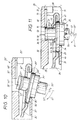
- Fig. 10
- eine Ausführung nach dem Stand der Technik, wo in Vergrößerung und in einem der Fig. 3 entsprechenden Schnitt das Hinterende eines fertig montierten Verbinders gezeigt ist, und zwar bei einer Fehlbedienung durch ein Drehwerkzeug,
- Fig. 11
- in einer der Fig. 10 entsprechenden Vergrößerung und Schnittdarstellung das Ende des zum ersten Ausführungsbeispiel der Erfindung gehörenden Verbinders, der vorausgehend in den Fig. 1 bis 9 bereits gezeigt worden ist und
- Fig. 12
- in einer der Fig. 11 entsprechenden Darstellung ein zweites Ausführungsbeispiel eines Verbinders nach der Erfindung.
- Fig. 1
- the sectional side view through a prepared connection point of a frame with two sections of the two profile bars to be connected in front of their coupling, the cut being shown in section line 1-1 of FIG. 2,
- 2, 3 and 4
- the cut plan views of the not yet coupled connection point with the profile bars shown in FIG. 1, the cut along the three cutting lines II-II, III-III and IV-IV of Fig. 1 can be seen and in Fig. 3 one Component is in an impression position,
- Fig. 5
- 3 shows a sectional top view corresponding to FIG. 3, the coupling position of the two profile bars at the connection point when the mentioned component is no longer pressed in axially but is in an initial position due to a spring force,
- Fig. 6
- 1 corresponding plan view of a housing belonging to the connector, before assembly of two further components shown in FIG. 7 on the one hand and FIGS. 8 and 9 on the other hand,
- Fig. 7
- 2 shows the first component, namely an eccentric bolt, partially broken away, which is mounted in the housing of FIG. 6, in a plan view corresponding to FIG. 2,
- 8 and 9
- the top view and the front view of the second component, namely a plate-shaped, profiled holding member which is to be assembled together with the eccentric bolt from FIG. 7 in the housing recognizable from FIG. 6,
- Fig. 10
- 3 shows an embodiment according to the prior art, where the rear end of a fully assembled connector is shown in an enlarged view and in a section corresponding to FIG. 3, namely in the event of incorrect operation by a turning tool,
- Fig. 11
- in an enlargement and sectional view corresponding to FIG. 10, the end of the connector belonging to the first embodiment of the invention, which has already been shown in FIGS. 1 to 9 and
- Fig. 12
- in a representation corresponding to FIG. 11, a second embodiment of a connector according to the invention.
Durch einen Verbinder 20 sollen jeweils zwei Profilstangen 10, 11 zu einem
Gestell miteinander gekuppelt werden. Dazu wird der Verbinder 20 mit
seinem Gehäuse 23 in einen Hohlraum 12 der einen Profilstange 10 eingesteckt
im Sinne des aus Fig. 3 ersichtlichen Einsteckpfeils 15. Dann ragen
aus der Stirnfläche 13 der Profilstange 10 zwei bewegliche Hakenenden
22, 22' eines plattenförmigen Halteglieds 24 und zwei starre Nasen 21,
21' heraus, die sich am vorderen Ende des Gehäuses 23 befinden. Im Kupplungsfall
greifen die beiden Nasen 21 und die Hakenenden 22, 22', wie
aus Fig. 5 zu erkennen ist, in eine hinterschnittene Nut 14 der anderen
Profilstange 11 ein. Diese Profilstange 11 besteht im dargestellten Ausführungsbeispiel
aus einer vertikalen achteckigen Säule.With a
Der Verbinder ist eine vorgefertigte Baueinheit, für welchen, im vorliegenden
Fall, nur drei Bestandteile erforderlich sind. Dazu gehört außer dem
erwähnten Gehäuse 23 und dem plattenförmigen Halteglied 24 noch ein
Exzenterbolzen 25, der in Fig. 7 gezeigt und nur halbseitig im Gehäuse
23 drehgelagert ist. Ausweislich der Fig. 1, 4 und 5 hat das Gehäuse
23 eine dem Hohlraumprofil der Profilstange 10 angepaßte Quaderform
und umfaßt eine Deckwand 31 sowie eine Bodenwand 32, welche durch
zwei Seitenwände miteinander verbunden sind, von denen die eine Seitenwand
33 in Fig. 2 erkennbar ist. Wie am besten aus Fig. 6 zu entnehmen ist,
besitzt die dort punktschraffiert hervorgehobene Deckwand 31 einen zum
Hinterende 30 des Gehäuses hin offenen Ausschnitt 34, der zur Drehlagerung
des in Fig. 7 erkennbaren abgesetzten äußeren Bolzenendes 26 vom Exzenterbolzen
25 dient. Dies ist besonders gut aus der in Fig. 11 gezeigten
Vergrößerung zu erkennen. In der Bodenwand 32 befindet sich eine Bohrung
35, in welche sich normalerweise das gegenüberliegende innere Bolzenende
27 nicht eingreift, wie aus Fig. 4 und 11 zu entnehmen ist. Die Bodenwand
32 ist aber im Bereich der Bohrung 35 gestuft ausgebildet, so daß sich
durch die Stufe eine halbseitige, ebenfalls zum Hinterende 30 hin offene
schalenförmige Stufen-Stoßfläche 36 ergibt, an welcher das innere Bolzenende
27 halbseitig anliegt. Der Exzenterbolzen 25 dient zur Bewegung des
Haltegliedes 24 in Richtung der Pfeile 40 bzw. 40' von Fig. 1, 4 und
5 im Inneren des Gehäuses 23. Dazu hat das Halteglied 24 folgenden,
aus Fig. 8 und 9 ersichtlichen Aufbau.The connector is a prefabricated unit, for which, in the present
Case, only three components are required. This also includes
mentioned
Im hinteren Plattenbereich besitzt das Halteglied 24 einen Durchbruch
44, der im Montagefall von einem Mittelabschnitt 28 des Bolzens gemäß
Fig. 4 und 11 durchragt wird. Zum vorderen Plattenende hin ist ein Längsschlitz
43 im Halteglied 24 vorgesehen, der zwei zueinander spiegelbildlich
verkröpfte Plattenstreifen 41, 41' mit den bereits erwähnten und zueinander
gegensinnig gebogenen Hakenenden 22, 22' erzeugt. Am Hinterende der
Platte besitzt das Halteglied 24 eine Steuerfläche 42, welche im vorliegenden
Ausführungsbeispiel aus einer zu den Hakenenden 22, 22' hin erfolgten
Rückfaltung des Plattenmaterials entsteht. Diese Steuerfläche 42 liegt
im Montagefall an einer zum Exzenterbolzen 25 gehörenden Exzenterscheibe
29 an, wie aus Fig. 1, 4 und 11 zu entnehmen ist. Das Halteglied besitzt
auch noch eine der Steuerfläche 42 entgegengerichtete Gegensteuerfläche
45, die im Montagefall an der gegenüberliegenden Seite der Exzenterscheibe
29 angreift.The holding
Der Verbinder 20 wird außerhalb seiner Profilstange 10 komplett vormontiert.
Dazu wird zunächst der Exzenterbolzen 25 durch den erwähnten
Durchbruch 44 in der Platte des Halteglieds 24 hindurchgesteckt, wobei
ein in Fig. 7 erkennbarer Radialabsatz 51 des Exzenterbolzens 25 die später
der Gehäuse-Deckwand 31 zugekehrte äußere Flächenseite 46 des Halteglieds
24 berührt. Im vorliegenden Fall ist dieser Radialabsatz durch die
gegenüber dem abgesetzten äußeren Bolzenende 26 vorspringende innere
Scheibenfläche der Exzenterscheibe 29 gebildet. Die beiden Bauteile 24,
27 werden nun durch die am Hinterende 30 in Fig. 6 erkennbare Öffnung
ins Innere des Gehäuses 23 eingeschoben. Dies wird durch einen Montagepfeil
16 in Fig. 6 verdeutlicht. Dabei fahren die beiden Plattenstreifen 41,
41' von hinten ins Gehäuse ein, bis sie, wie aus Fig. 3 und 4 zu ersehen
ist, mit Schrägflächen 47, 47' hinter ihnen zugeordnete Gegenschrägen
37, 37' im vorderen Bereich des Gehäuses 23 fahren. Dazu besitzen sowohl
die Deckwand 31 als auch die Bodenwand 32 gegeneinander gerichtete
napfförmige Anformungen 38, 38' und Fenster 39, 39', die im Höhenversatz
in den beiden Gehäusewänden 31, 32 angeordnet sind und paarweise einander
gegenüberliegen, was aus Fig. 3 und 6 zu erkennen ist. Die Gegenschrägen
37, 37' entstehen durch ansteigende, gegeneinander gerichtete Innenflächen
dieser Anformungen 38, 38', die dann ein Teilstück wandparallel laufen
und schließlich, wieder zueinander gegensinnig, abfallen. Durch diesen
Abfall entstehen die am besten aus Fig. 5 ersichtlichen Auflaufschrägen
19, 19' für die erwähnte Montage des Halteglieds 24 im Sinne des Einschubpfeils
16 von Fig. 6.The
Bei dieser Montage 16 ist auf eine definierte Drehlage der Exzenterscheibe
29 bezüglich der am Halteglied 24 vorgesehenen Steuerfläche 42 zu achten.
Dazu ist eine Marke 52 hilfreich, die sich an der Stirnfläche des äußeren
Bolzenendes 26 gemäßt Fig. 1 befindet. Diese Drehlage soll nachfolgend
"Ausgangsdrehlage" bezeichnet werden. Zur Sicherung dieser Ausgangsdrehlage
während der Montage besitzt die in Fig. 6 erkennbare Innenseite der
Bodenwand 32 einen rippenförmigen Montagevorsprung, und, wie am besten
im Ausbruch von Fig. 7 zu erkennen ist, das innere Bolzenende 27 an
seinem Stirnbereich eine rinnenförmige, diametrale Montageaussparung
53. Das Ende der Einschubbewegung 16 ist erreicht, wenn das äußere Bolzenende
26 im halbkreisförmigen Ausschnitt 34 der Gehäuse-Deckwand
31 und das innere Bolzenende 27 an der schalenförmigen Stufen-Stoßfläche
36 der Gehäuse-Bodenwand 32 zur Anlage kommen. Dann hintergreifen
die beschriebenen Schrägflächen 47, 47' an den beiden Plattenstreifen
41, 41' die beiden gehäuseseitigen Gegenschrägen 37, 37', wie bereits beschrieben
wurde. Dann ist zwar, gemäß Fig. 11, die Exzenterscheibe 29
an ihrer dem Ausschnitt 34 gegenüberliegenden Seite von der zum Halteglied
24 gehörenden Steuerfläche 42 hintergriffen, doch liegt dem zur Bohrung
35 der Bodenwand 32 zugekehrten Ende des rippenförmigen Montagevorsprungs
48 die Rinnenöffnung 53 der im Exzenterbolzen 25 befindlichen
Montageaussparung 53 gegenüber.In this
Der Exzenterbolzen 25 steht unter der Wirkung einer axialen Federkraft,
die in Fig. 3, 5 und 11 durch einen Kraftpfeil 50 veranschaulicht ist. Diese
Federkraft 50 könnte zwar von einer unmittelbar auf den Exzenterbolzen
25 einwirkenden Feder erzeugt werden, doch erfolgt dies im vorliegenden
Fall mittelbar durch das Halteglied 24. Dazu kann z. B. eine Wendelfeder
verwendet werden, welche zunächst auf die in Fig. 8 und 9 erkennbare
innere Flächenseite 49 des Halteglieds 24 wirkt. Die Federkraft wirkt
dann durch die erwähnte äußere Flächenseite 46 des Halteglieds 24 auf
die sich dort abstützende Radialstufe 51 am Exzenterbolzen 25.The
Im vorliegenden Ausführungsbeispiel wird diese axiale Federkraft 50 auf
wesentlich einfacherere Weise erreicht, wie aus Fig. 3 und 5 zu erkennen
ist. Die Platte des Halteglieds 24 besteht aus federelastischem Material,
wie Federstahl, und besitzt eine ausgeschnittene Federzunge 18. Diese
Federzunge 18 entsteht im vorliegenden Fall durch eine Gabelung des erwähnten
Längsschlitzes 43 und wird von dem zwischen den beiden Plattenstreifen
41, 41' befindlichen Plattenmaterial erzeugt. Das freie Zungenende
ist zwar zu den beiden Hakenenden 22, 22' der Plattenstreifen 41, 41'
hin gerichtet, aber demgegenüber zurückgesetzt. Außerdem ist die Federzunge
18, wie Fig. 8 verdeutlicht, aus der mittleren Ebene des Plattenmaterials
herausgebogen und stützt sich nach der Montage an der Innenseite der
aus Fig. 3 und 5 erkennbaren Gehäuse-Bodenwand 32 ab. In diesem Bereich
kann die Bodenwand 32 auch mit einer aus Fig. 5 erkennbaren Vertiefung
58 versehen sein, die zur Positionierung des freien Zungenendes dient.In the present exemplary embodiment, this
Die vom Halteglied 24 auf den erwähnten Radialabsatz 51 des Bolzens
25 ausgeübte Federkraft 50 hält den Exzenterbolzen 25 normalerweise
in der aus Fig. 11 ersichtlichen Axialposition, wo das äußere Bolzenende
26 über die äußere Begrenzung der Gehäuse-Deckwand 31 axial vorspringt.
Diese Position ergibt sich, weil der Exzenterbolzen 25 an seinem äußeren
Ende 26 auch noch einen radialen Gegenabsatz 54 gemäß Fig. 7 besitzt,
der hier von der äußeren Scheibenfläche des Exzenters 29 gebildet ist
und sich, ausweislich der Fig. 11, an der Innenseite der Gehäuse-Deckwand
31 abstützt. Das aus dem Gehäuse 23 axial vorspringende äußere Bolzenende
26 greift im Einbauzustand in der Profilstange 10, wie am besten aus
Fig. 2 hervorgeht, in ein seitliches Querloch 17 der Profilstange 10 hinein.
Dadurch wird der Verbinder 20 in einer definierten Längslage in der Profilstange
10 festgehalten. Die erwähnten Hakenenden 22, 22' ragen zusammen
mit den Nasen 21, 21' in definierter Weise aus der Stirnfläche 13 der
Profilstange 10 heraus. Der Verbinder 20 kann aus einer Einbaulage in
der Profilstange 10 wieder ausgebaut werden, indem man auf das im Profilstangen-Querloch
17 sichtbare äußere Bolzenende 26 die durch einen Pfeil
60 in Fig. 2 und 3 verdeutlichte Eindrückkraft ausübt. Bei diesem Eindrücken
60 taucht das in Fig. 11 ersichtliche innere Bolzenende 27 in
die Bohrung 25 der Gehäuse-Bodenwand 32 axial ein, bis, ausweislich der
Fig. 3, das äußere Bolzenende 26 nicht mehr über die Außenseite der Gehäuse-Deckwand
31 vorspringt. Fig. 3 zeigt also die volle Eindrückposition
des Exzenterbolzens 25, wo das Querloch 17 der Profilstange 10 freigegeben
ist. Dann läßt sich der ganze Verbinder 20 im Sinne des Pfeils 15' wieder
aus dem Stangen-Hohlraum 12 herausziehen.The from the holding
Der Einbau des Verbinders 20 im Sinne des bereits beschriebenen EinsteckPfeils
15 von Fig. 3 erfolgt in analoger Weise. Beim vormontierten Verbinder
20 wird der Exzenterbolzen 25 mit seinem Bolzenende 26 druckknopfartig
eingedrückt, bis sein äußeres Bolzenende 26 nicht mehr aus der Gehäuse-Deckwand
31 vorspringt. Dann wird der Verbinder 20 von der Stirnfläche
13 der Profilstange 10 aus eingeführt, bis sein unter axialer Federkraft
50 stehender Exzenterbolzen 25 in das Querloch 17 einschnappt. Es liegt
dann die Position von Fig. 2 oder 4 vor. In Fig. 2 sind die beiden Hakenenden
22, 22' in ihrer vollen Ausfahrstellung weitgehend gegeneinander geklappt.
Sie liegen in fluchtender Lage zwischen den beiden feststehenden
Gehäuse-Nasen 21, 21'. Die Hakenenden 22, 22' nehmen in der Ausfahrstellung
des Halteglieds 24 eine minimale Breite ein, die sich bequem durch
eine schmale Eintrittsöffnung ins Innere der Nut 14 der anderen Profilstange
11 einführen läßt.The installation of the
Der Exzenterbolzen 25 kann mittels eines Drehwerkzeugs 55 aus seiner
Ausgangsdrehlage in Fig. 1 im Gehäuse 23 verstellt werden. Dazu ist
eine unrund profilierte Werkzeugaufnahme 56 im Stirnbereich des äußeren
Bolzenendes 26 vorgesehen. Bei einer solchen, aus Fig. 11 erkennbaren
Werkzeugdrehung 57, drückt die sich drehende Exzenterscheibe 29 die beschriebene
Steuerfläche 42 nach hinten und es findet die durch den bereits
erwähnten Bewegungspfeil 40 veranschaulichte Längsbewegung des Halteglieds
im Gehäuse 23 statt. Dadurch werden die beiden Hakenenden 22, 22' aus
ihrer in Fig. 1 bis 4 ersichtlichen maximalen Ausfahrstellung in ihre in
Fig. 5 gezeigte Einziehstellung überführt. Durch Zusammenwirken der
Schrägflächen 47, 47' der beiden Plattenstreifen 41, 41' mit den ihnen
zugeordneten gehäuseseitigen Gegenschrägen 37, 37' kommt es bei der
Einzugsbewegung 40 auch noch zu einer in Fig. 5 erkennbaren Spreizung
der beiden Hakenenden 22, 22'. Die beiden Hakenenden 22, 22' sind
dann auf eine große Breite auseinandergespreizt und hintergreifen, wie
Fig. 5 zeigt, die hinterschnittenen Innenflächen der Profilstangen-Nut
14. Bei dieser Längsbewegung 40 kommt es schließlich noch zu einem
Zusammenpressen der die Nut 14 in der Profilstange 11 erzeugenden Profilwände
zwischen der Stirnfläche 13 der zum Verbinder 20 gehörenden Profilstange
10 einerseits und den gegenüberliegenden beiden Hakenenden 22,
22' andererseits. Es liegt eine schraubstockartige Verspannung vor. Die
beiden Profilstangen 10, 11 sind sehr zuverlässig miteinander verbunden.
In diesem Fall befindet sich der Exzenterbolzen 25 in seiner zu Fig. 1
um 180° versetzten, diametralen Enddrehlage, die durch die entsprechende
Position der beschriebenen Marke 52 ablesbar ist. Diese Enddrehlage kann
durch einen Drehanschlag 59 am Exzenterbolzen 25 gemäß Fig. 7 und
ein geeignetes stufenförmiges Öffnungsprofil vom Durchbruch 44 im Halteglied
24, gemäß Fig. 9, begrenzt sein.The
Zum Lösen der beiden Profilstangen 11 braucht der Exzenterbolzen 25
über das Drehwerkzeug 55 lediglich in die aus Fig. 11 ersichtliche Gegendrehrichtung
57' betätigt zu werden. Dann erfolgt über die Exzenterscheibe
29 und die am Halteglied 24 vorgesehene, bereits erwähnte Gegensteuerfläche
45 die im Sinne des bereits erwähnten Pfeils 40' wirksame Lägnsbewegung
des Halteglieds 24. Dann werden die beiden Hakenenden 22, 22' wieder
in ihre Ausfahrstellung überführt, bis schließlich die volle Ausgangsdrehlage
gemäß Fig. 1 vorliegt. Wegen der ihrem Plattenmaterial innewohnenden
Federspannung werden die beiden heraus fahrenden Hakenenden
22, 22' auf den gehäuseseitigen Gegenschrägen 37, 37' wieder gegeneinander
geführt, so daß schließlich wieder die Ausgangsposition von Fig. 1 bis
4 erreicht ist.The
In der Ausgangsdrehlage ist das innere Bolzenende 27 zum Hinterende
30 des Gehäuses 23 hin frei, weil die beschriebene Montageaussparung
53 mit ihrer Rinnenöffnung zum rippenförmigen Montagevorsprung 48 an
der Gehäuse-Bodenwand 32 hin frei liegt. Es besteht, ohne die noch näher
zu beschreibenden besonderen erfindungsgemäßen Maßnahmen, die Gefahr,
daß sich der Exzenterbolzen verkippt, was anhand der Fig. 10 verdeutlicht
werden soll. In Fig. 10 ist ein Verbinder 20'' nach dem Stand der Technik
in einer der Fig. 11 entsprechenden Darstellung gezeigt. Zur Bezeichnung
der dortigen Bauteile werden die gleichen Bezugszeichen wie im vorbeschriebenen
Ausführungsbeispiel der Erfindung verwendet, aber zur Unterscheidung
davon, mit einem Doppelstrich ('') gekennzeichnet. Es gilt insoweit die
bisherige Beschreibung. Aus Fig. 10 ist folgendes zu erkennen.In the initial rotational position, the
Bei eingestecktem Drehwerkzeug 55'' läßt sich der Exzenterbolzen 25''
in Richtung des Pfeiles 61'' soweit abwinkeln, daß seine Exzenterscheibe
29'' nicht mehr an der Steuerfläche 42'' des dortigen Haltegliedes 24''
anliegt. Das innere Bolzenende 27'' ist nämlich nicht allseitig in der
Gehäusebohrung 35'' drehgelagert. Die rinnenförmige Montageaussparung
53'' kann sich bei diesem Verkippen 61 am rippenförmigen Montagevorsprung
48'' des Gehäuses 23'' vorbeibewegen. Die äußere Scheibenfläche 54''
der Exzenterscheibe 29'' stützt sich an der Kante des Gehäuse-Ausschnitts
34'' in der Gehäuse-Deckwand 31'' ab und das Hinterende des Halteglieds
24'' läßt sich gegen die axiale Federbelastung zur Gehäuse-Bodenwand
32'' hin zurückdrücken. In dieser Kipp-Position ist der Exzenterbolzen
25'' nicht daran gehindert, über das Drehwerkzeug 55'' in der beschriebenen
Weise, gemäß dem Drehpfeil 57'' von Fig. 10, verdreht zu werden und
der exzentrische Bereich der Scheibe 29'' läuft vor dem rückgebogenen
Hinterende des Halteglieds 24'' vorbei, wie strichpunktiert in Fig. 10 verdeutlicht
ist. Dann liegt die Steuerfläche 42'' vom Hinterende des Halteglieds
an der inneren Scheibenfläche 51'' des Exzenters 29'' und nicht
an deren exzentrischen Umfangsfläche an. Es liegt eine Fehlbedienung
vor.When the turning tool 55 '' is inserted, the eccentric pin 25 ''
Bend in the direction of arrow 61 '' until its eccentric disc
29 '' no longer on the control surface 42 '' of the holding member 24 '' there
is present. The inner bolt end 27 '' is namely not on all sides in the
Housing bore 35 '' pivoted. The channel-shaped mounting recess
53 '' can be on the rib-shaped mounting projection during this tilting 61
48 '' of the housing 23 ''. The outer pane surface 54 ''
the eccentric 29 '' is supported on the edge of the housing cutout
34 '' in the housing top wall 31 '' and the rear end of the holding member
24 '' can be against the axial spring load to the housing bottom wall
Push back 32 ''. The eccentric pin is in this tilt position
25 '' not prevented from turning tool 55 '' as described in the
Way, according to the
Wenn die Bedienungsperson das Verkippen 61 nicht erkennt, ist sie aufgrund
der Drehung 57'' der irrigen Ansicht, die Enddrehlage des Exzenterbolzens
25'' erreicht zu haben, welche - wenn diese Fehlbedienung nicht vorliegt
- die beschriebene Kupplung zwischen den beiden Profilstangen 10, 11
über die beiden Hakenenden kennzeichnet. Bei dieser Fehlbedienung aber
ist weder die beschriebene Längsbewegung des Halteglieds 24'' erfolgt
noch ist die in Fig. 5 beschriebene Querbewegung der beiden Hakenenden
eingetreten. Die beiden Profilstangen 10, 11 sind nicht miteinander verbunden.
Das kann zu schwerwiegenden Unfällen führen. Die in Fig. 10 strichpunktiert
angedeutete Fehlsteuerung der Exzenterscheibe 29" ist von außen
nicht sichtbar, wenn der Verbinder in einer Profilstange eingebaut ist,
die in Fig. 10 nicht mitgezeichnet wurde. Die Kippbewegung 61 des Exzenters
wird nämlich auch nicht durch das beschriebene Querloch in der Profilstange
verhindert, in welche das verkippte äußere Bolzenende 26" im Einbauzustand
eingreift.If the operator does not recognize the
Bei der erfindungsgemäßen Ausführung gemäß Fig. 11 ist ein Verkippen
im Sinne des dortigen Kippbewegungs-Pfeils 61 weitgehend verhindert.
Wie Fig. 8 und 9 zeigen, ist das Halteglied 24 bei diesem Ausführungsbeispiel
in seinem hinteren Bereich mit einer dellenartigen Verformung 62
versehen, welche sich unmittelbar an den beschriebenen Plattendurchbruch
44 anschließt. Diese dellenartige Verformung 62 erzeugt eine Stütze 63,
welche in der in Fig. 11 gezeigten Ausgangsdrehlage des Exzenterbolzens
25 zur Drehführung des Exzenterbolzens in dessen Mittelabschnitt 28 dient.
An der durch die Rinnenöffnung der Montageaussparung 53 ungesicherten
Seite des Exzenterbolzens 25, die dem Hinterende 30 des Gehäuses 23
zugekehrt ist, befindet sich jetzt eine zusätzliche Drehführungsstütze
63 für den Exzenterbolzen 25, welche ein Verkippen 61 des Exzenterbolzens
25 verhindert und somit dessen ordnungsgemäße Vertikallage sichert. Im
weiteren Vollzug der Drehung 57 greift die der Bohrung 35 zugekehrte
Endfläche 70 des rippenförmigen Montagevorsprungs 48 an der Umfangsfläche
des inneren Bolzenendes 27 an und verhindert damit bereits eine Kippbewegung
61.In the embodiment according to the invention according to FIG. 11, it is tilting
largely prevented in the sense of the tilting
Im vorliegenden Fall ist die Drehführungsstütze 63 nur an einer Stelle
des Bolzenumfangs wirksam, nämlich an derjenigen, wo der erwähnte Ausschnitt
34 der Gehäuse-Deckwand 31 offen ist, nämlich zum Hinterende
30 des Gehäuses 23 hin. Ausweislich der Fig. 8 und 9 befindet sich die
beschriebene Steuerfläche 42 aufgrund der Rückbiegung der Platte an
der äußeren Flächenseite 46 des Plattenmaterials, während die Drehführungsstütze
63 gegenüberliegend, an der inneren Flächenseite 49, angeordnet
ist und in Richtung auf das in Fig. 11 erkennbare innere Bolzenende 27
hin axial vorsteht.In the present case, the
In Fig. 12 ist ein zweites Ausführungsbeispiel der Erfindung erläutert, wobei zur Benennung der entsprechenden Bauteile die gleichen Bezugszeichen wie im bisherigen ersten Ausführungsbeispiel gemäß Fig. 1 bis 9 und Fig. 11 verwendet worden sind. Insoweit gilt die bisherige Beschreibung. Es genügt, lediglich auf die Unterschiede einzugehen.12 illustrates a second exemplary embodiment of the invention, the same reference numerals being used to designate the corresponding components as in the previous first exemplary embodiment according to FIGS. 1 to 9 and FIG. 11 have been used. In this respect, the previous description applies. It it is enough to only consider the differences.
Bei der Montage des Verbinders 20 von Fig. 12 wird das Halteglied 24
zusammen mit dem durch seinen Durchbruch 44 hindurchgesteckten Exzenterbolzen
25 in der beschriebenen Weise durch die Gehäuse-Öffnung im
Hinterende 30 des Gehäuses eingeschoben und in eine ausgerichtete Lage
mit der Bohrung 35 in der Gehäuse-Bodenwand 32 gebracht. In diesem
Ausführungsbeispiel besitzt die Bohrung 35 einen gegenüber dem ersten
Ausführungsbeispiel größeren Bohrungsdurchmesser 65 und erlaubt dadurch
das nachträgliche Aufsetzen einer Hülse 66, die mindestens den mit der
rinnenförmigen Montageaussparung 53 versehenen Bereich des inneren Bolzenendes
27 abdeckt. Im vorliegenden Fall erstreckt sich die Hülse aber auch
noch auf den angrenzenden Mittelabschnitt 28 des Exzenterbolzens 25.
Dadurch entsteht zwischen der äußeren Stirnfläche 67 der Hülse 66 und
der beschriebenen inneren Scheibenfläche 51 des Exzenters 29 eine ringförmige
Nut 68, in welche, wie bei 69 in Fig. 12 erkennbar, das Plattenmaterial
des Halteglieds 24 mit der den Platten-Durchbruch 44 umgrenzenden
Randzone bereichsweise eingreift. Diese äußere Hülsen-Stirnfläche 67 ist
der Innenfläche 49 der Halteglied-Platte 24 zugekehrt, während die innere
Scheibenfläche 51 des Exzenters 29 an der äußeren Flächenseite 46 anliegt.When the
Die Hülse 66 ist durch Preßsitz od. dgl. fest mit dem Schaft 27, 28 des
Exzenterbolzens 25 verbunden. Die Umfangsfläche 64 der Hülse 66 wirkt
wie ein Lagerzapfen, der jetzt nicht nur an der schalenförmigen Stoßfläche
36 im Stufenbereich der GehäuseBodenwand 32, sondern auch gegenüberliegend,
an der in Fig. 12 erkennbaren Endfläche 70 des rippenförmigen Montagevorsprungs
48 anliegt. Dadurch entsteht dort eine beidseitige Lageraufnahme
für den Hülsenumfang 64. Versucht man über das eingesteckte Drehwerkzeug
55 den Exzenterbolzen 25 im Sinne des Pfeils 61 von Fig. 12 zu
verkippen, so stößt der Hülsenumfang 64 an der Vorsprungs-Endfläche
70 an. Dadurch ist die ordnungsgemäße Position des Exzenterbolzens 25
im Gehäuse 23 und damit die stets ausgerichtete Position seiner Exzenterscheibe
29 mit der am Halteglied 24 vorgesehenen Steuerfläche 42 gewährleistet. The
Wie schon Fig. 6 zeigt, ist das Gehäuse 23 mit Anschlagflächen 71 versehen,
welche die im Zusammenhang mit Fig. 3 beschriebene axiale Eindrückbewegung
60 des Exzenterbolzens 25 dann verhindern sollen, wenn nicht mehr
die in Fig. 1 gezeigte Ausgangsdrehlage des Exzenterbolzens 25 vorliegt.
In der Ausgangsdrehlage befinden sich die Anschlagflächen 71 außerhalb
sämtlicher beim Eindrücken 60 axial beweglicher Teile, z. B. außerhalb
des Endes vom plattenförmigen Haltelgied 24.Bei der Eindrückbewegung
60 bewegen sich im dargestellten Ausführungsbeispiel nicht nur der Exzenterbolzen
25, sondern auch die angrenzenden Bereiche des Halteglieds
24 axial mit. Spätestens dann, wenn die aus Fig. 5 erkennbare Enddrehlage
vorliegt, ist diese Anschlagfläche 71 mit den axial beweglichen Bauteilen
ausgerichtet; nämlich im vorliegenden Fall mit der erwähnten inneren Fläche
49 des plattenförmigen Halteglieds 24. Eine hier durch den strichpunktierten
Pfeil 60 in Fig. 5 verdeutlichte Kraft 60 kann den Exzenterbolzen
25 nicht mehr axial eindrücken, weil sich dieser über seinen Radialabsatz
an der äußeren Fläche der Halteglied-Platte 24 abstützt. Die innere Plattenfläche
49 ist nämlich auf die Anschlagfläche 71 gefahren. Jetzt ist der
Exzenterbolzen 25 blockiert. Eine Druckknopfbetätigung ist nicht mehr
möglich und folglich der Verbinder 20 in seiner Einbaulage in der Profilstange
10 gesichert.As already shown in FIG. 6, the
Im dargestellten Ausführungsbeispiel befindet sich die Anschlagfläche 71
kurz vor dem Hinterende 30 des Gehäuses und besteht aus der zur Deckwand
31 weisenden Fläche eines im Gehäuseinneren angeformten Auflaufbocks
72, der am besten aus Fig. 11 erkennbar ist. Ausweislich der Fig.
6 ist der Auflaufbock 72 in zwei Teilböcke gegliedert, zwischen denen
ein Längskanal für die beschriebene Einschubmontage des Exzenterbolzens
25 sich befindet und wo der Montagevorsprung 48 angordnet ist. In diesem
Ausführungsbeispiel entsteht vor dem Auflaufbock 72 ein aus Fig. 11 erkennbarer
Freiraum 73, in welchen sich die beim Eindrücken 60 der axial beweglichen
Bauteile, nämlich im vorliegenden Fall das Hinterende des Halteglieds
24, dann hineinbewegen kann, wenn die Ausgangsdrehstellung von Fig.
11 bzw. 1 vorliegt. Das axiale Eindrücken des äußeren Bolzenendes 26
ist möglich und es kann der beschriebene Einbau oder Ausbau des Verbinders
20 aus der Profilstange 10 erfolgen.In the exemplary embodiment shown, the
Es versteht sich, daß solche Anschlagflächen 71 und Freiräume 73 auch
in anderer Weise ausgebildet sein könnten. So ist es z. B. möglich, axiale
Abwinkelungen oder axiale Vorsprünge am Plattenmaterial des Halteglieds
24 vorzusehen. In diesem Fall könnte die Anschlagfläche 71 von einem
Bodenbereich der Gehäuse-Bodenwand 32 gebildet sein, während der davor
liegende Freiraum 73 durch einen Ausbruch in der Gehäuse-Bodenwand
32 erzeugt wird. It goes without saying that such stop surfaces 71 and
- 1010th
- Profilstange für 20Profile bar for 20
- 1111
- andere Profilstangeother profile bar
- 1212th
- Hohlraum in 10Cavity in 10th
- 1313
- Stirnfläche von 10Face of 10
- 1414
- Nut in 11Groove in 11
- 1515
- Einsteck-Pfeil für 20 in 12 (Fig. 3)Insert arrow for 20 in 12 (Fig. 3)
- 15'15 '
- Herausziehpfeil für 20 in 12 (Fig. 3)Pull-out arrow for 20 in 12 (Fig. 3)
- 1616
- Einschub-Montagepfeil (Fig. 6)Insert assembly arrow (Fig. 6)
- 1717th
- Querloch von 10Cross hole of 10
- 1818th
- Federzunge von 24 (Fig. 8. 9)Spring tongue of 24 (Fig. 8. 9)
- 19, 19'19, 19 '
- Auflaufschräge bei 38, 38' (Fig. 5)Run-up slope at 38, 38 '(Fig. 5)
- 2020th
- VerbinderInterconnects
- 20"20 "
- Verbinder nach dem Stand der TechnikState of the art connectors
- 21, 21'21, 21 '
- feste Nase an 23firm nose at 23
- 22, 22'22, 22 '
- Hakenende von 24Hook end of 24
- 2323
- Gehäuse von 20Housing of 20
- 24, 24"24, 24 "
- plattenförmiges Haltegliedplate-shaped holding member
- 25, 25"25, 25 "
- ExzenterbolzenEccentric bolt
- 26, 26"26, 26 "
- äußeres Bolzenende von 25outer bolt end of 25
- 27, 27"27, 27 "
- inneres Bolzenende von 25inner bolt end of 25
- 2828
- Bolzen-Mittelstück von 25Center pin of 25
- 29, 29"29, 29 "
- Exzenterscheibe von 25, ExzenterEccentric disc from 25, eccentric
- 3030th
- Hinterende von 23Rear end of 23
- 31, 31"31, 31 "
- Deckwand von 23Top wall of 23
- 32, 32"32, 32 "
- Bodenwand von 23Bottom wall of 23
- 3333
- Seitenwand von 23Sidewall of 23
- 34, 34"34, 34 "
- Ausschnitt in 31Detail in 31
- 35, 35"35, 35 "
- Bohrung in 32, Aufnahme in 23Hole in 32, hole in 23
- 3636
- schalenförmige Stoßfläche bei 35cup-shaped joint surface at 35
- 37, 37'37, 37 '
- Gegenschräge bei 23Counter-slopes at 23
- 38, 38'38, 38 '
- napfförmige Anformungen bei 31 bzw. 32Cup-shaped formations at 31 or 32
- 39, 39'39, 39 '
- Fenster in 31, 32Windows in 31, 32
- 4040
- kupplungswirksamer Längsbewegungs-Pfeil (Fig. 4)clutch-effective longitudinal movement arrow (Fig. 4)
- 40'40 '
- entkupplungswirksamer Längsbewegungs-Pfeil (Fig. 5)decoupling-effective longitudinal movement arrow (Fig. 5)
- 41, 41'41, 41 '
- Plattenstreifen von 24Plate strips from 24
- 42, 42"42, 42 "
- Steuerfläche an 24Control surface on 24
- 4343
- Längsschlitz in 24Longitudinal slot in 24
- 4444
- Durchbruch in 24Breakthrough in 24
- 4545
- Gegensteuerfläche an 24 (Fig. 8)Counter control surface at 24 (Fig. 8)
- 4646
- äußere Flächenseite von 24outer surface side of 24
- 47, 47'47, 47 '
- Schrägflächen an 41, 41' Sloping faces at 41, 41 '
- 48, 48"48, 48 "
- rippenförmiger Montagevorsprung an 32 bzw. 32" (Fig. 6)rib-shaped mounting projection on 32 or 32 "(Fig. 6)
- 4949
- innere Flächenseite von 24inner surface side of 24
- 5050
- Pfeil der axialen FederkraftAxial spring force arrow
- 51, 51"51, 51 "
- Radialabsatz von 25, innere Scheibenfläche von 29 bzw. 29"Radial shoulder of 25, inner disc area of 29 or 29 "
- 5252
- Marke an 26 (Fig. 1)Mark at 26 (Fig. 1)
- 53, 53"53, 53 "
- rinnenförmige Montageaussparung bei 27 (Fig. 7, 10)trough-shaped mounting recess at 27 (Fig. 7, 10)
- 54, 54"54, 54 "
- radialer Gegenabsatz von 25, äußere Scheibenfläche (Fig. 7, 10)radial counterpart of 25, outer disc surface (Fig. 7, 10)
- 55, 55"55, 55 "
- DrehwerkzeugTurning tool
- 5656
- Werkzeugaufnahme in 26 (Fig. 1)Tool holder in 26 (Fig. 1)
- 5757
- Werkzeugdrehung (Fig. 11)Tool rotation (Fig. 11)
- 57'57 '
- Werkzeug-Gegendrehung (Fig. 11)Tool counter rotation (Fig. 11)
- 57"57 "
- Werkzeugdrehung nach dem Stand der Technik (Fig. 10)Tool rotation according to the prior art (Fig. 10)
- 5858
- Vertiefung in 32 (Fig. 5)Depression in 32 (Fig. 5)
- 5959
- Drehanschlag von 25 (Fig. 7)Turning stop of 25 (Fig. 7)
- 6060
- Eindrück-PfeilImpression arrow
- 61, 61"61, 61 "
- Kippbewegungs-PfeilTilting arrow
- 6262
- dellenartige Verformung bei 24dent-like deformation at 24
- 6363
- Stütze, Drehführungsstütze von 62Support, rotating guide support from 62
- 6464
- Hülsen-Umfangsfläche von 66Sleeve circumferential surface of 66
- 6565
- vergrößerter Durchmesser von 35 (Fig. 12)enlarged diameter of 35 (Fig. 12)
- 6666
- Hülse (Fig. 12)Sleeve (Fig. 12)
- 6767
- äußere Stirnfläche von 66outer end face of 66
- 6868
- RingnutRing groove
- 6969
- Plattenmaterial von 24Plate material from 24
- 7070
- Endfläche von 48. Bereich von 48End face of 48. area of 48
- 7171
- Anschlagfläche bei 72Stop surface at 72
- 7272
- AuflaufbockHeadstock
- 7373
- Freiraum bei 23Free space at 23
Claims (13)
- A framework comprising releasably connectable profile bars (10, 11)of which at least some have undercut grooves (14) and others have an end cavity (12) for the insertion of a housing (23) which belongs to a connector (20) and which movably (40, 40') accommodates a holding member (24),the holding member (24) has at least one hook end (22, 22') which projects at the end out of the profile bar and which is transversely movably guided in the housing (23) and which can be coupled to the groove (14) of the other profile bar (11),wherein an axially spring-loaded eccentric pin (25) passes through the holding member (24) and has an eccentric disc (29) which bears at least against a control surface (42) on the holding member (24) and upon rotary actuation (57, 57') of the eccentric pin (25) serves to produce the movement (40, 40') of the holding member (24),and the outer pin end (26) which serves for rotary actuation (57, 57') of the eccentric pin (25) and/or the oppositely disposed inner pin end (27) are rotatably supported only in a place-wise manner in the housing (23) and give rise to the danger of a tilting movement (61) of the eccentric pin (25) in the housing (23),characterised in that the holding member (24) has a support (rotary guide support 63) which is axially set back with respect to the control surface (42) of the holding member towards the inner pin end (27) and at which the eccentric pin (25) is rotatably guided (Figures 1 to 9 and 11).
- A framework according to claim 1 characterised in that the housing (23) has a top wall (31) and a bottom wall (32),and the outer pin end (26) of the eccentric pin (25) which serves at the same time for rotary actuation (57, 57') of the eccentric pin is rotatably supported at a half side in an opening (34) in the housing top wall (31), the opening being open towards the rear end (30) of the housing (23), and normally axially resiliently engages into a transverse hole (17) in the profile bar but can be axially urged (60) into the housing against said spring loading (50),while the inner pin end (27) of the eccentric pin (25) is normally disposed substantially axially outside a receiving means (35) in the bottom wall (32) of the housing but moves into said receiving means (35) when the eccentric pin (25) is urged axially (60) into the housing.
- A framework according to claim 1 or claim 2 characterised in that the rotary guide support (63) only engages the side of the eccentric pin (25), where the opening (34) in the housing (23) opens.
- A framework according to one or more of claims 1 to 3 characterised in that the holding member (24) comprises a profiled plate, at the outer flat side (46) of which is disposed the control surface (42) for the eccentric disc (29) and at the inner flat side (49) of which the rotary guide support (63) for the eccentric pin (25) axially projects.
- A framework according to one or more of claims 1 to 4 characterised in that the rotary guide support (23) comprises a hollow-shaped deformation (62) of the plate material.
- A framework comprising releasably connectable profile bars (10, 11)of which at least some have undercut grooves (14) and others have an end cavity (12) for the insertion of a housing (23) which belongs to a connector (20) and which movably (40, 40') accommodates a holding member (24),the holding member (24) has at least one hook end (22, 22') which projects at the end out of the profile bar and which is transversely movably guided in the housing (23) and which can be coupled to the groove (14) of the other profile bar (11),wherein an axially spring-loaded eccentric pin (25) passes through the holding member (24) and has an eccentric disc (29) which bears at least against a control surface (42) on the holding member (24) and upon rotary actuation (57, 57') of the eccentric pin (25) serves to produce the movement (40, 40') of the holding member (24),and the outer pin end (26) which serves for rotary actuation (57, 57') of the eccentric pin (25) and/or the oppositely disposed inner pin end (27) are rotatably supported only in a place-wise manner in the housing (23) and give rise to the danger of a tilting movement (61) of the eccentric pin (25) in the housing (23),wherein, for rotationally oriented insertion assembly (16) of the eccentric pin (25) in the housing (23), the inner pin end (27) has an assembly recess (53) in the end region and the bottom wall (32) of the housing (23) has an assembly projection (48),characterised in that a cover (66) for radially closing the assembly recess (53) is carried at the inner pin end (27) of the eccentric pin (25) in the fully assembled condition, andthe peripheral surface (64) of the cover (66) is rotatably guided at least in the region (70) of the assembly projection (48) (Figure 12).
- A framework according to claim 6 characterised in that the housing (23) has a top wall (31) and a bottom wall (32),and the outer pin end (26) of the eccentric pin (25) which serves at the same time for rotary actuation (57, 57') of the eccentric pin is rotatably supported at a half side in an opening (34) in the housing top wall (31), the opening being open towards the rear end (30) of the housing (23), and normally axially resiliently engages into a transverse hole (17) in the profile bar but can be axially urged (60) into the housing against said spring loading (50),while the inner pin end (27) of the eccentric pin (25) is normally disposed substantially axially outside a receiving means (35) in the bottom wall (32) of the housing but moves into said receiving means (35) when the eccentric pin (25) is urged axially (60) into the housing.
- A framework according to claim 6 or claim 7 characterised in that the cover comprises a sleeve (66) which encloses the inner pin end (27).
- A framework according to one or more of claims 6 to 8 characterised in that the holding member (24) comprises a profiled plate,the two flat sides (46, 49) of which in the assembly situation come to bear on the one hand against a radial step (51) of the eccentric pin (25) and on the other hand against the cover (66), andbetween the radial step (51) of the eccentric pin (25) and the cover (66) is a radial groove (68) into which the plate material of the holding member (24) engages.
- A framework according to one or more of claims 1 to 9 characterised in that the axial spring force (50) is applied to the eccentric pin (25) by way of the plate-shaped holding member (24) and the eccentric pin (25) is supported by way of a radial step (51) against the outer flat side (54) of the plate-shaped holding member (24).
- A framework according to claim 10 characterised in that the eccentric disc (29) of the eccentric pin (25) with its inner disc surface forms the radial step which bears against the holding member (24).
- A framework according to one or more of claims 1 to 11 characterised in that the plate of the holding member (24) comprises resilient material and has a cut-out resilient tongue (18) which bears slidably against an inside surface of the housing (23) and produces the axial spring force (50) for the eccentric pin (25).
- A framework according to one or more of claims 1 to 12 characterised in that on the one hand the housing (23) has an axial free space which permits the outer pin end (26) to be axially pushed in (60) in an initial rotary position (Figures 1 to 4) of the eccentric pin (25), that determines the uncoupled position of the hook end (22, 22'),but on the other hand the housing bottom wall (32) has an abutment surface (71) which blocks the axial inward pushing movement (60) in any other rotary position, in particular a final rotary position (Figure 5) of the eccentric pin (25), that defines the coupled position of the hook end (22, 22').
Applications Claiming Priority (2)
| Application Number | Priority Date | Filing Date | Title |
|---|---|---|---|
| DE19500340 | 1995-01-07 | ||
| DE19500340A DE19500340C1 (en) | 1995-01-07 | 1995-01-07 | Frame made from detachably connected shaped rods |
Publications (3)
| Publication Number | Publication Date |
|---|---|
| EP0721068A2 EP0721068A2 (en) | 1996-07-10 |
| EP0721068A3 EP0721068A3 (en) | 1996-08-07 |
| EP0721068B1 true EP0721068B1 (en) | 1999-03-24 |
Family
ID=7751115
Family Applications (1)
| Application Number | Title | Priority Date | Filing Date |
|---|---|---|---|
| EP95115379A Expired - Lifetime EP0721068B1 (en) | 1995-01-07 | 1995-09-29 | Frame consisting of detachable profiles |
Country Status (4)
| Country | Link |
|---|---|
| EP (1) | EP0721068B1 (en) |
| AT (1) | ATE178124T1 (en) |
| DE (2) | DE19500340C1 (en) |
| ES (1) | ES2129167T3 (en) |
Families Citing this family (4)
| Publication number | Priority date | Publication date | Assignee | Title |
|---|---|---|---|---|
| DE10318940A1 (en) * | 2003-04-26 | 2004-11-25 | Vießmann Kältetechnik AG | Turnbuckle especially for connecting wall components |
| CN100410550C (en) * | 2005-10-14 | 2008-08-13 | 常州灵通展览用品有限公司 | Assembling connecting lock of display rack |
| EP2455624A1 (en) * | 2009-10-16 | 2012-05-23 | Changzhou Lingtong Exhibition Products Co. Ltd. | Connecting locker |
| CN109764035B (en) * | 2019-01-30 | 2023-06-23 | 湖南朗乐科技股份有限公司 | Internal stay type pipe connecting device |
Family Cites Families (3)
| Publication number | Priority date | Publication date | Assignee | Title |
|---|---|---|---|---|
| DE3128595C2 (en) * | 1981-07-20 | 1990-12-06 | Gebrüder Vieler GmbH, 5860 Iserlohn | Frame made of detachably connectable profile bars |
| DE3927979C5 (en) * | 1989-08-11 | 2008-05-21 | Vieler International Gmbh + Co. Kg | Frame made of releasably connectable by a connector with each other profile rods |
| DE4219717A1 (en) * | 1992-06-17 | 1993-12-23 | Rodwyl Trading Ag Allschwil | Connector for positioning frame and support - has sleeve between retaining element and housing, and has accommodation for eccentric bolthead and locks in frame unit |
-
1995
- 1995-01-07 DE DE19500340A patent/DE19500340C1/en not_active Expired - Lifetime
- 1995-09-29 AT AT95115379T patent/ATE178124T1/en not_active IP Right Cessation
- 1995-09-29 DE DE59505436T patent/DE59505436D1/en not_active Expired - Lifetime
- 1995-09-29 ES ES95115379T patent/ES2129167T3/en not_active Expired - Lifetime
- 1995-09-29 EP EP95115379A patent/EP0721068B1/en not_active Expired - Lifetime
Also Published As
| Publication number | Publication date |
|---|---|
| ATE178124T1 (en) | 1999-04-15 |
| EP0721068A2 (en) | 1996-07-10 |
| DE59505436D1 (en) | 1999-04-29 |
| ES2129167T3 (en) | 1999-06-01 |
| EP0721068A3 (en) | 1996-08-07 |
| DE19500340C1 (en) | 1996-05-02 |
Similar Documents
| Publication | Publication Date | Title |
|---|---|---|
| EP0139954B1 (en) | Frame consisting of detachable structural members | |
| EP0261267B2 (en) | Bar lock for sheet steel cabinet doors | |
| DE3714039C2 (en) | ||
| EP0412339B1 (en) | Means for connecting profiled beams of a rack | |
| DE3112097C2 (en) | "Safety switch" | |
| EP0371153B1 (en) | Connection device | |
| DE10002215C1 (en) | Automobile door handle has outer cable of cable mechanism between door handle operating element and door closure mechanism provided with automatic length adjustment | |
| EP0840336A2 (en) | Self-adjusting tappet-switch, in particular brake ligth switch | |
| EP0721068B1 (en) | Frame consisting of detachable profiles | |
| EP0228527A2 (en) | Door or window fitting | |
| EP0754827A2 (en) | Device for releasable and non-sliding of a handle on a bearing element, especially for door handles or window handles | |
| EP2156060B1 (en) | Fastener for detachably connecting a profile to a counterprofile | |
| EP0166794B1 (en) | Means for connecting profiled beams of a rack | |
| EP0178369A2 (en) | Fastening element | |
| DE3320193C2 (en) | Door fitting | |
| EP1920126B1 (en) | Actuation device for a lock | |
| DE2723887B2 (en) | Fixing device for lock cylinder | |
| DE4013158C1 (en) | Roller blind covering car boot - incorporates swing arm passing through blind casing and pushbutton control | |
| DE3153232C2 (en) | Framework comprising profile rods which can be connected in a releasable manner | |
| EP1329338A2 (en) | Writing implement | |
| EP0118910B1 (en) | Locking cylinder | |
| CH691870A5 (en) | Rotary actuator. | |
| EP1061208A2 (en) | Espagnolette lock for sheet metal cabinet doors | |
| EP0438630B1 (en) | Explosion-protected lamp holder | |
| DE3322292C2 (en) | Safety switch with false locking device |
Legal Events
| Date | Code | Title | Description |
|---|---|---|---|
| PUAI | Public reference made under article 153(3) epc to a published international application that has entered the european phase |
Free format text: ORIGINAL CODE: 0009012 |
|
| PUAL | Search report despatched |
Free format text: ORIGINAL CODE: 0009013 |
|
| AK | Designated contracting states |
Kind code of ref document: A2 Designated state(s): AT CH DE DK ES FR GB IT LI NL SE |
|
| AK | Designated contracting states |
Kind code of ref document: A3 Designated state(s): AT CH DE DK ES FR GB IT LI NL SE |
|
| 17P | Request for examination filed |
Effective date: 19961219 |
|
| GRAG | Despatch of communication of intention to grant |
Free format text: ORIGINAL CODE: EPIDOS AGRA |
|
| 17Q | First examination report despatched |
Effective date: 19980716 |
|
| GRAG | Despatch of communication of intention to grant |
Free format text: ORIGINAL CODE: EPIDOS AGRA |
|
| GRAH | Despatch of communication of intention to grant a patent |
Free format text: ORIGINAL CODE: EPIDOS IGRA |
|
| GRAH | Despatch of communication of intention to grant a patent |
Free format text: ORIGINAL CODE: EPIDOS IGRA |
|
| GRAA | (expected) grant |
Free format text: ORIGINAL CODE: 0009210 |
|
| AK | Designated contracting states |
Kind code of ref document: B1 Designated state(s): AT CH DE DK ES FR GB IT LI NL SE |
|
| PG25 | Lapsed in a contracting state [announced via postgrant information from national office to epo] |
Ref country code: SE Free format text: THE PATENT HAS BEEN ANNULLED BY A DECISION OF A NATIONAL AUTHORITY Effective date: 19990324 |
|
| REF | Corresponds to: |
Ref document number: 178124 Country of ref document: AT Date of ref document: 19990415 Kind code of ref document: T |
|
| ITF | It: translation for a ep patent filed |
Owner name: CALVANI SALVI E VERONELLI S.R.L. |
|
| REG | Reference to a national code |
Ref country code: CH Ref legal event code: EP |
|
| GBT | Gb: translation of ep patent filed (gb section 77(6)(a)/1977) |
Effective date: 19990325 |
|
| REF | Corresponds to: |
Ref document number: 59505436 Country of ref document: DE Date of ref document: 19990429 |
|
| REG | Reference to a national code |
Ref country code: ES Ref legal event code: FG2A Ref document number: 2129167 Country of ref document: ES Kind code of ref document: T3 |
|
| ET | Fr: translation filed | ||
| PG25 | Lapsed in a contracting state [announced via postgrant information from national office to epo] |
Ref country code: DK Free format text: LAPSE BECAUSE OF FAILURE TO SUBMIT A TRANSLATION OF THE DESCRIPTION OR TO PAY THE FEE WITHIN THE PRESCRIBED TIME-LIMIT Effective date: 19990624 |
|
| PG25 | Lapsed in a contracting state [announced via postgrant information from national office to epo] |
Ref country code: AT Free format text: LAPSE BECAUSE OF NON-PAYMENT OF DUE FEES Effective date: 19990929 |
|
| PG25 | Lapsed in a contracting state [announced via postgrant information from national office to epo] |
Ref country code: LI Free format text: LAPSE BECAUSE OF NON-PAYMENT OF DUE FEES Effective date: 19990930 Ref country code: CH Free format text: LAPSE BECAUSE OF NON-PAYMENT OF DUE FEES Effective date: 19990930 |
|
| PLBE | No opposition filed within time limit |
Free format text: ORIGINAL CODE: 0009261 |
|
| STAA | Information on the status of an ep patent application or granted ep patent |
Free format text: STATUS: NO OPPOSITION FILED WITHIN TIME LIMIT |
|
| 26N | No opposition filed | ||
| REG | Reference to a national code |
Ref country code: CH Ref legal event code: PL |
|
| REG | Reference to a national code |
Ref country code: GB Ref legal event code: IF02 |
|
| PGFP | Annual fee paid to national office [announced via postgrant information from national office to epo] |
Ref country code: GB Payment date: 20120925 Year of fee payment: 18 |
|
| PGFP | Annual fee paid to national office [announced via postgrant information from national office to epo] |
Ref country code: IT Payment date: 20120922 Year of fee payment: 18 Ref country code: DE Payment date: 20120914 Year of fee payment: 18 Ref country code: ES Payment date: 20120907 Year of fee payment: 18 |
|
| PGFP | Annual fee paid to national office [announced via postgrant information from national office to epo] |
Ref country code: FR Payment date: 20121011 Year of fee payment: 18 |
|
| PGFP | Annual fee paid to national office [announced via postgrant information from national office to epo] |
Ref country code: NL Payment date: 20120917 Year of fee payment: 18 |
|
| REG | Reference to a national code |
Ref country code: DE Ref legal event code: R231 Ref document number: 59505436 Country of ref document: DE |
|
| PG25 | Lapsed in a contracting state [announced via postgrant information from national office to epo] |
Ref country code: DE Free format text: LAPSE BECAUSE OF THE APPLICANT RENOUNCES Effective date: 20130925 |
|
| REG | Reference to a national code |
Ref country code: NL Ref legal event code: V1 Effective date: 20140401 |
|
| GBPC | Gb: european patent ceased through non-payment of renewal fee |
Effective date: 20130929 |
|
| REG | Reference to a national code |
Ref country code: FR Ref legal event code: ST Effective date: 20140530 |
|
| PG25 | Lapsed in a contracting state [announced via postgrant information from national office to epo] |
Ref country code: GB Free format text: LAPSE BECAUSE OF NON-PAYMENT OF DUE FEES Effective date: 20130929 |
|
| PG25 | Lapsed in a contracting state [announced via postgrant information from national office to epo] |
Ref country code: FR Free format text: LAPSE BECAUSE OF NON-PAYMENT OF DUE FEES Effective date: 20130930 Ref country code: IT Free format text: LAPSE BECAUSE OF NON-PAYMENT OF DUE FEES Effective date: 20130929 Ref country code: NL Free format text: LAPSE BECAUSE OF NON-PAYMENT OF DUE FEES Effective date: 20140401 |
|
| REG | Reference to a national code |
Ref country code: ES Ref legal event code: FD2A Effective date: 20141007 |
|
| PG25 | Lapsed in a contracting state [announced via postgrant information from national office to epo] |
Ref country code: ES Free format text: LAPSE BECAUSE OF NON-PAYMENT OF DUE FEES Effective date: 20130930 |